EP0712969A2 - Removable and versatile modular metal structure - Google Patents
Removable and versatile modular metal structure Download PDFInfo
- Publication number
- EP0712969A2 EP0712969A2 EP95500148A EP95500148A EP0712969A2 EP 0712969 A2 EP0712969 A2 EP 0712969A2 EP 95500148 A EP95500148 A EP 95500148A EP 95500148 A EP95500148 A EP 95500148A EP 0712969 A2 EP0712969 A2 EP 0712969A2
- Authority
- EP
- European Patent Office
- Prior art keywords
- profiles
- profile
- removable
- modular
- clamp
- Prior art date
- Legal status (The legal status is an assumption and is not a legal conclusion. Google has not performed a legal analysis and makes no representation as to the accuracy of the status listed.)
- Granted
Links
- 229910052751 metal Inorganic materials 0.000 title claims description 12
- 239000002184 metal Substances 0.000 title claims description 12
- 238000010276 construction Methods 0.000 claims description 11
- 238000005192 partition Methods 0.000 description 3
- 230000000694 effects Effects 0.000 description 2
- 229910052782 aluminium Inorganic materials 0.000 description 1
- XAGFODPZIPBFFR-UHFFFAOYSA-N aluminium Chemical compound [Al] XAGFODPZIPBFFR-UHFFFAOYSA-N 0.000 description 1
- 238000012512 characterization method Methods 0.000 description 1
- 230000002860 competitive effect Effects 0.000 description 1
- 230000000295 complement effect Effects 0.000 description 1
- 238000009792 diffusion process Methods 0.000 description 1
- 239000000463 material Substances 0.000 description 1
- 230000000750 progressive effect Effects 0.000 description 1
Images


Classifications
-
- E—FIXED CONSTRUCTIONS
- E04—BUILDING
- E04H—BUILDINGS OR LIKE STRUCTURES FOR PARTICULAR PURPOSES; SWIMMING OR SPLASH BATHS OR POOLS; MASTS; FENCING; TENTS OR CANOPIES, IN GENERAL
- E04H1/00—Buildings or groups of buildings for dwelling or office purposes; General layout, e.g. modular co-ordination or staggered storeys
- E04H1/12—Small buildings or other erections for limited occupation, erected in the open air or arranged in buildings, e.g. kiosks, waiting shelters for bus stops or for filling stations, roofs for railway platforms, watchmen's huts or dressing cubicles
- E04H1/1272—Exhibition stands
-
- E—FIXED CONSTRUCTIONS
- E04—BUILDING
- E04B—GENERAL BUILDING CONSTRUCTIONS; WALLS, e.g. PARTITIONS; ROOFS; FLOORS; CEILINGS; INSULATION OR OTHER PROTECTION OF BUILDINGS
- E04B2/00—Walls, e.g. partitions, for buildings; Wall construction with regard to insulation; Connections specially adapted to walls
- E04B2/74—Removable non-load-bearing partitions; Partitions with a free upper edge
- E04B2/76—Removable non-load-bearing partitions; Partitions with a free upper edge with framework or posts of metal
- E04B2/766—T-connections
-
- E—FIXED CONSTRUCTIONS
- E04—BUILDING
- E04B—GENERAL BUILDING CONSTRUCTIONS; WALLS, e.g. PARTITIONS; ROOFS; FLOORS; CEILINGS; INSULATION OR OTHER PROTECTION OF BUILDINGS
- E04B1/00—Constructions in general; Structures which are not restricted either to walls, e.g. partitions, or floors or ceilings or roofs
- E04B1/38—Connections for building structures in general
- E04B1/58—Connections for building structures in general of bar-shaped building elements
- E04B2001/5868—Hinged connections
-
- E—FIXED CONSTRUCTIONS
- E04—BUILDING
- E04B—GENERAL BUILDING CONSTRUCTIONS; WALLS, e.g. PARTITIONS; ROOFS; FLOORS; CEILINGS; INSULATION OR OTHER PROTECTION OF BUILDINGS
- E04B1/00—Constructions in general; Structures which are not restricted either to walls, e.g. partitions, or floors or ceilings or roofs
- E04B1/38—Connections for building structures in general
- E04B1/58—Connections for building structures in general of bar-shaped building elements
- E04B2001/5881—Connections for building structures in general of bar-shaped building elements using an undercut groove, e.g. dovetail groove
-
- F—MECHANICAL ENGINEERING; LIGHTING; HEATING; WEAPONS; BLASTING
- F16—ENGINEERING ELEMENTS AND UNITS; GENERAL MEASURES FOR PRODUCING AND MAINTAINING EFFECTIVE FUNCTIONING OF MACHINES OR INSTALLATIONS; THERMAL INSULATION IN GENERAL
- F16B—DEVICES FOR FASTENING OR SECURING CONSTRUCTIONAL ELEMENTS OR MACHINE PARTS TOGETHER, e.g. NAILS, BOLTS, CIRCLIPS, CLAMPS, CLIPS OR WEDGES; JOINTS OR JOINTING
- F16B2200/00—Constructional details of connections not covered for in other groups of this subclass
- F16B2200/20—Connections with hook-like parts gripping behind a blind side of an element to be connected
-
- F—MECHANICAL ENGINEERING; LIGHTING; HEATING; WEAPONS; BLASTING
- F16—ENGINEERING ELEMENTS AND UNITS; GENERAL MEASURES FOR PRODUCING AND MAINTAINING EFFECTIVE FUNCTIONING OF MACHINES OR INSTALLATIONS; THERMAL INSULATION IN GENERAL
- F16B—DEVICES FOR FASTENING OR SECURING CONSTRUCTIONAL ELEMENTS OR MACHINE PARTS TOGETHER, e.g. NAILS, BOLTS, CIRCLIPS, CLAMPS, CLIPS OR WEDGES; JOINTS OR JOINTING
- F16B2200/00—Constructional details of connections not covered for in other groups of this subclass
- F16B2200/20—Connections with hook-like parts gripping behind a blind side of an element to be connected
- F16B2200/205—Connections with hook-like parts gripping behind a blind side of an element to be connected the hook being a separate retainer
-
- F—MECHANICAL ENGINEERING; LIGHTING; HEATING; WEAPONS; BLASTING
- F16—ENGINEERING ELEMENTS AND UNITS; GENERAL MEASURES FOR PRODUCING AND MAINTAINING EFFECTIVE FUNCTIONING OF MACHINES OR INSTALLATIONS; THERMAL INSULATION IN GENERAL
- F16B—DEVICES FOR FASTENING OR SECURING CONSTRUCTIONAL ELEMENTS OR MACHINE PARTS TOGETHER, e.g. NAILS, BOLTS, CIRCLIPS, CLAMPS, CLIPS OR WEDGES; JOINTS OR JOINTING
- F16B2200/00—Constructional details of connections not covered for in other groups of this subclass
- F16B2200/40—Clamping arrangements where clamping parts are received in recesses of elements to be connected
-
- Y—GENERAL TAGGING OF NEW TECHNOLOGICAL DEVELOPMENTS; GENERAL TAGGING OF CROSS-SECTIONAL TECHNOLOGIES SPANNING OVER SEVERAL SECTIONS OF THE IPC; TECHNICAL SUBJECTS COVERED BY FORMER USPC CROSS-REFERENCE ART COLLECTIONS [XRACs] AND DIGESTS
- Y10—TECHNICAL SUBJECTS COVERED BY FORMER USPC
- Y10T—TECHNICAL SUBJECTS COVERED BY FORMER US CLASSIFICATION
- Y10T403/00—Joints and connections
- Y10T403/34—Branched
- Y10T403/341—Three or more radiating members
-
- Y—GENERAL TAGGING OF NEW TECHNOLOGICAL DEVELOPMENTS; GENERAL TAGGING OF CROSS-SECTIONAL TECHNOLOGIES SPANNING OVER SEVERAL SECTIONS OF THE IPC; TECHNICAL SUBJECTS COVERED BY FORMER USPC CROSS-REFERENCE ART COLLECTIONS [XRACs] AND DIGESTS
- Y10—TECHNICAL SUBJECTS COVERED BY FORMER USPC
- Y10T—TECHNICAL SUBJECTS COVERED BY FORMER US CLASSIFICATION
- Y10T403/00—Joints and connections
- Y10T403/46—Rod end to transverse side of member
- Y10T403/4602—Corner joint
-
- Y—GENERAL TAGGING OF NEW TECHNOLOGICAL DEVELOPMENTS; GENERAL TAGGING OF CROSS-SECTIONAL TECHNOLOGIES SPANNING OVER SEVERAL SECTIONS OF THE IPC; TECHNICAL SUBJECTS COVERED BY FORMER USPC CROSS-REFERENCE ART COLLECTIONS [XRACs] AND DIGESTS
- Y10—TECHNICAL SUBJECTS COVERED BY FORMER USPC
- Y10T—TECHNICAL SUBJECTS COVERED BY FORMER US CLASSIFICATION
- Y10T403/00—Joints and connections
- Y10T403/55—Member ends joined by inserted section
- Y10T403/557—Expansible section
-
- Y—GENERAL TAGGING OF NEW TECHNOLOGICAL DEVELOPMENTS; GENERAL TAGGING OF CROSS-SECTIONAL TECHNOLOGIES SPANNING OVER SEVERAL SECTIONS OF THE IPC; TECHNICAL SUBJECTS COVERED BY FORMER USPC CROSS-REFERENCE ART COLLECTIONS [XRACs] AND DIGESTS
- Y10—TECHNICAL SUBJECTS COVERED BY FORMER USPC
- Y10T—TECHNICAL SUBJECTS COVERED BY FORMER US CLASSIFICATION
- Y10T403/00—Joints and connections
- Y10T403/70—Interfitted members
- Y10T403/7005—Lugged member, rotary engagement
Definitions
- the invention object of this memorandum refers to a metal structure, of the modular configuration type, made through the combination of a minimal series of assembly and connecting elements determining a large range of building shapes and elements.
- the solution herein advanced consists of a combination of various types of metal work profiles with a number of assembly parts, resulting in complex and very varied connections and devices.
- variable angle and articulation connection devices consist of a set of profile transversal connection elements featuring a double part, shaped like a clamp, articulated at one of its ends by an internal semi-cylindrical projection that fits into a similarly shaped opening practised into the other half of the clamp shaped part.
- each half part has a different length and is arranged so that it tightens up as a slanted joint, by closing the shortest part, fitted with the semi-cylindrical projection, upon the other.
- This end portion has projections and slots that fit into other opposing internal elements on the wing of a supporting profile.
- the double part is introduced, already assembled, into the housing duly arranged for the purposes of embedding the clamp, made of a transversal profile to which this clamp is then joined.
- One the half parts has, centrally located and near this clamp lip contact area, a threaded hole for the passage of an Allen bolt which, at the same time, passes through one of the clamp embedment profile surfaces, coinciding said hole with an internal transversal rectangular rib on one of the half parts, identical to another on the opposite half part, upon which frontal surface rests the Allen bolt, pressing against and, because of the progressive pressure, opening the clamp through articulation until it fits rigidly inside the housing profile, thus lending rigidity to the joint between the two transversal profiles.
- the clamp may be cut slant wise from two of its opposite diagonal vertices of one of its larger surfaces, so that said cut allows it to fit into a profile also cut slant wise, thus configuring a tie, a railing post, a slanted panel, etc.
- the rigid connection devices are made from an octagonal section profile out of which vertices come out externally and radially two fins forming a double consecutive arrow tip that determine, between each two profiles, two channels where either irregularly shaped washers with fitting circular sector cuts and other full external ones for tightening are introduced, or alternatively the external washers may be substituted by a tubular part, of external octagonal shape, that operates as a guide and as a support to a traversal connection profile.
- a profile with a core square section and with extensions on two, three or on its four sides, fitted with projections and re-sunk, may also be arranged, with a function identical to those described in the foregoing octagonal core profile and with to same purpose as them, whereas non symmetrical in respect of the extension axis, as the first ones.
- the surfaces that do not have said projections enabling connection between profiles are arranged with a convex curved finish.
- the fundamental profiles to be combined with each other and through the use of assembly parts have an angular connection, at 45°, 90° and 135° angles, within a same plane, using central projections of the profile frame, which constitute the profile core that make up the beams, pillars, transoms, footings, shoring, etc.
- To these frames may also be attached, orthogonal to the plane of the angular profile, one or two profiles that assemble onto as many frame transversal projections, which are fitted with different external shapes, polygonal or curved side polygonal. Internally these profiles may have an octagonal or square core.
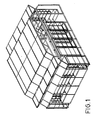
- Figure 1 represents a kiosk designed to sell newspapers and for other services, incorporating some of the non detailed arrangements, some of those described in respect of these connection devices through articulation and of variable angle, of rigid connection and assembly profiles.
- Figure 2 represents a double detail, shown on plan view and exploded view, of the articulation and variable angle connection device, in its orthogonal and slanted executions.
- Figure 3 is another detail of some of the rigid connection devices used to configure an octagonal core structure.
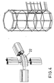
- Figure 4 is a detail of one of the rigid connection devices used to configure a square core structure, as well as a perspective view of its application in an octagonal display case.
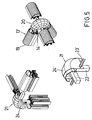
- Figure 5 shows a randomly chosen example of the joints of parts determining the structure and ready to receive the panel holding profiles, display cases, etc. at 45° and 90° angled finishes.
- the devices used for connection through articulation and with variable angles, for transversal profile connection have a clamp shaped double part (1) and (1'), articulated at one of its ends by a semi-cylindrical projection (2) of the half part (1) that fits into an opening (3) practised on the other half part (2), whereas the opposite ends, of different lengths, are arranged on slanted contact (4) with projections (5) and openings (6) that fit into similarly shaped devices on the wing of a supporting profile (7) to which they are fastened, whereas the rest of the clamp is then introduced into the boxlike structure (8) of a transversal profile (9) to which the clamp is then fastened through the action of a bolt (10) passing through a hole (11) and a rib (12) that exerts pressure against another rib (12') on the opposite half part (1'), giving rigidity to the joint between both transversal profiles (7) and (9).
- the clamp may be cut slant wise, so that it fits into a similarly slant wise cut profile (9'), configuring a tie, a railing, a slanted panel, etc. all of the foregoing without losing its capacity to adapt itself, through the use of variable angles, to the general requirements of the structure.
- the rigid connection devices start off an octagonal profile (13) fitted with radial fins (14) that determine channels (15), where are introduced either fitting washers (16) together with fastening washers (16) or else said washers (16) and an octagonal part (17), that works as a guide and support of a conventional carrying profile.
- a square profile (13') with fins (14') projecting out of two, three or its four surfaces, with a function identical to that of the fins (14) and with its surfaces (19) not fitted with said fins (14') featuring a convex curved finish, may also be arranged.
- the profiles are assembled using rigid angular connection parts at angles of 45° (20), 90° (21) and 135° (22), within a single plane, using articulated axes (23) capable of being screwed onto the frame (24) which then constitute the core of the profile acting as a beam, pillar, transom, footing, shoring, etc., being the frames (24') capable of being assembled into as many profiles using the remaining transversal axis (23') of the frame, which may be configured either just polygonally or polygonally with a curved side, whereas the profiles may internally have their octagonal or square core, as a function of the extension of the part.
Landscapes
- Architecture (AREA)
- Engineering & Computer Science (AREA)
- Civil Engineering (AREA)
- Structural Engineering (AREA)
- Physics & Mathematics (AREA)
- Electromagnetism (AREA)
- Joining Of Building Structures In Genera (AREA)
- Mutual Connection Of Rods And Tubes (AREA)
- Surgical Instruments (AREA)
- Biological Depolymerization Polymers (AREA)
- Materials For Medical Uses (AREA)
- Clamps And Clips (AREA)
- Supports For Pipes And Cables (AREA)
- Tents Or Canopies (AREA)
- Cookers (AREA)
- Connection Of Plates (AREA)
Abstract
Description
- The invention object of this memorandum refers to a metal structure, of the modular configuration type, made through the combination of a minimal series of assembly and connecting elements determining a large range of building shapes and elements.
- Whereas the fundamental application of this construction is the assembly of trade fair type stands and elements accessories to stands, other applications may not be readily discarded, including some of the fixed type such as walls, partitions, etc.
- It is made up of profiles set in multiple combinations with anchor elements that determine connections between complete shelf stands and partitions, among themselves and together with other construction elements such as ceilings, display cases, open display elements, etc. with a large variety of combinations of connection devices, some of them rigid and others articulated and of variable angular setting.
- The wide diffusion of aluminum based work, in a wide number of new activities as well as in others traditionally reserved to conventional ironwork has generated an extremely diverse multiplicity of profiles and parts used to connect them together.
- In fields such as fixed or sliding partitions, rotating, sliding or articulated doors, as well as in large continuous enclosures the progress achieved in the construction of these new profiles has been outstanding.
- Notwithstanding the foregoing, there are fixed structure applications that are structured so that they may be taken apart for later successive extensions, in the same way that there are others that are taken apart again after brief periods of use, such as stands at trade fairs and exhibitions. Both types require connection devices and assembly and disassembly means that must necessarily be of the fast operation type, in order to make these products competitive, which requires the existence of profiles and connection parts specially prepared for these purposes, profiles and parts not normally found in the market.
- The existence of rigid joining parts may be similarly observed in the construction of conventional metal work, with which it becomes impossible to play around with clearances to compensate for the structural adjustments normally required in metal work.
- The solution herein advanced consists of a combination of various types of metal work profiles with a number of assembly parts, resulting in complex and very varied connections and devices.
- The variable angle and articulation connection devices consist of a set of profile transversal connection elements featuring a double part, shaped like a clamp, articulated at one of its ends by an internal semi-cylindrical projection that fits into a similarly shaped opening practised into the other half of the clamp shaped part.
- The opposite end of each half part has a different length and is arranged so that it tightens up as a slanted joint, by closing the shortest part, fitted with the semi-cylindrical projection, upon the other.
- This end portion has projections and slots that fit into other opposing internal elements on the wing of a supporting profile.
- The double part is introduced, already assembled, into the housing duly arranged for the purposes of embedding the clamp, made of a transversal profile to which this clamp is then joined.
- One the half parts has, centrally located and near this clamp lip contact area, a threaded hole for the passage of an Allen bolt which, at the same time, passes through one of the clamp embedment profile surfaces, coinciding said hole with an internal transversal rectangular rib on one of the half parts, identical to another on the opposite half part, upon which frontal surface rests the Allen bolt, pressing against and, because of the progressive pressure, opening the clamp through articulation until it fits rigidly inside the housing profile, thus lending rigidity to the joint between the two transversal profiles.
- The clamp may be cut slant wise from two of its opposite diagonal vertices of one of its larger surfaces, so that said cut allows it to fit into a profile also cut slant wise, thus configuring a tie, a railing post, a slanted panel, etc.
- The rigid connection devices are made from an octagonal section profile out of which vertices come out externally and radially two fins forming a double consecutive arrow tip that determine, between each two profiles, two channels where either irregularly shaped washers with fitting circular sector cuts and other full external ones for tightening are introduced, or alternatively the external washers may be substituted by a tubular part, of external octagonal shape, that operates as a guide and as a support to a traversal connection profile.
- A profile with a core square section and with extensions on two, three or on its four sides, fitted with projections and re-sunk, may also be arranged, with a function identical to those described in the foregoing octagonal core profile and with to same purpose as them, whereas non symmetrical in respect of the extension axis, as the first ones.
- The surfaces that do not have said projections enabling connection between profiles are arranged with a convex curved finish.
- The fundamental profiles to be combined with each other and through the use of assembly parts have an angular connection, at 45°, 90° and 135° angles, within a same plane, using central projections of the profile frame, which constitute the profile core that make up the beams, pillars, transoms, footings, shoring, etc.
- To these frames may also be attached, orthogonal to the plane of the angular profile, one or two profiles that assemble onto as many frame transversal projections, which are fitted with different external shapes, polygonal or curved side polygonal. Internally these profiles may have an octagonal or square core.
- In order to complement the description being effected and so as to aid a better and easier understanding of the characteristics of the invention, this patent specification includes, as an integral part thereof, a set of drawings where the following has been duly represented for purely illustrative but not limitative purposes:
- Figure 1 represents a kiosk designed to sell newspapers and for other services, incorporating some of the non detailed arrangements, some of those described in respect of these connection devices through articulation and of variable angle, of rigid connection and assembly profiles.
- Figure 2 represents a double detail, shown on plan view and exploded view, of the articulation and variable angle connection device, in its orthogonal and slanted executions.
- Figure 3 is another detail of some of the rigid connection devices used to configure an octagonal core structure.
- Figure 4 is a detail of one of the rigid connection devices used to configure a square core structure, as well as a perspective view of its application in an octagonal display case.
- Figure 5 shows a randomly chosen example of the joints of parts determining the structure and ready to receive the panel holding profiles, display cases, etc. at 45° and 90° angled finishes.
- Upon studying the above commented figures, it may then be clearly observed how the invention hereby advanced consists of a combination of several series of metalwork profiles with other assembly parts, resulting in a wide variety of connection devices, through articulation and with variable angles, as well as to effect rigid connections.
- The devices used for connection through articulation and with variable angles, for transversal profile connection, have a clamp shaped double part (1) and (1'), articulated at one of its ends by a semi-cylindrical projection (2) of the half part (1) that fits into an opening (3) practised on the other half part (2), whereas the opposite ends, of different lengths, are arranged on slanted contact (4) with projections (5) and openings (6) that fit into similarly shaped devices on the wing of a supporting profile (7) to which they are fastened, whereas the rest of the clamp is then introduced into the boxlike structure (8) of a transversal profile (9) to which the clamp is then fastened through the action of a bolt (10) passing through a hole (11) and a rib (12) that exerts pressure against another rib (12') on the opposite half part (1'), giving rigidity to the joint between both transversal profiles (7) and (9).
- The clamp may be cut slant wise, so that it fits into a similarly slant wise cut profile (9'), configuring a tie, a railing, a slanted panel, etc. all of the foregoing without losing its capacity to adapt itself, through the use of variable angles, to the general requirements of the structure.
- The rigid connection devices start off an octagonal profile (13) fitted with radial fins (14) that determine channels (15), where are introduced either fitting washers (16) together with fastening washers (16) or else said washers (16) and an octagonal part (17), that works as a guide and support of a conventional carrying profile.
- A square profile (13') with fins (14') projecting out of two, three or its four surfaces, with a function identical to that of the fins (14) and with its surfaces (19) not fitted with said fins (14') featuring a convex curved finish, may also be arranged.
- The profiles are assembled using rigid angular connection parts at angles of 45° (20), 90° (21) and 135° (22), within a single plane, using articulated axes (23) capable of being screwed onto the frame (24) which then constitute the core of the profile acting as a beam, pillar, transom, footing, shoring, etc., being the frames (24') capable of being assembled into as many profiles using the remaining transversal axis (23') of the frame, which may be configured either just polygonally or polygonally with a curved side, whereas the profiles may internally have their octagonal or square core, as a function of the extension of the part.
- It is not considered necessary to extend this description any further to enable any expert on the art to understand the scope of the invention and the advantages derived therefrom, as well as to enable its reproduction.
- It is well understood that, as long as the essential features of the invention are not altered, both the materials and the shape, size and arrangement of the elements may be varied within the same characterization.
- The terms in which this specifications has been described must always be interpreted in a wide and non limitative sense.
Claims (7)
- Modular, removable and versatile metal construction, of the type configured as a combination of various series of metalwork profiles with other assembly parts, generating very varied connection devices, essentially characterized by its having variable angle and articulation connection devices, forming a clamp shaped double part (1) and (1') and rigid connection devices of external octagonal or square finned core (14) or (14') configuring channels (15) or (15') for the embedment of supporting guides for profiles appropriate for these devices.
- Modular, removable and versatile metal construction, as per the foregoing claim, characterized because the articulation and variable angle connection devices, used for transversal profile connection, making up a double clamp shaped part (1) and (1'), articulate it at one of its ends using a.semi-cylindrical projection (2) of the half part (2), whereas the opposite ends, of different length, are arranged in slanted contact (4) with projections (5) and openings (6) that fit into similarly shaped devices on the wing of a supporting profile (7) to which they are fastened, whereas the rest of the clamp is then introduced into the boxlike structure (8) of a transversal profile (9) to which the clamp is then fastened through the action of a bolt (10) passing through a hole (11) and a rib (12) that exerts pressure against another rib (12') on the opposite half part (1'), thus lending rigidity to the joint between both transversal profiles (7) and (9).
- Modular, removable and versatile metal construction, as per the foregoing claims, characterized because the clamp may be cut slant wise, without this reducing its variable angle connection capacity, which cut is effected so that it may be housed into a similarly slant wise cut profile (9'), configuring a tie, a railing, a slanted panel, and others.
- Modular, removable and versatile metal construction, as per the first claim, characterized because the rigid connection devices start off an octagonal profile (13) fitted with radial fins (14) that determine channels (15), where are introduced either fitting washers (16) together with fastening washers (16) or alternatively said washers (16) and an octagonal part (17), that works as a guide and support of a conventional carrying profile.
- Modular, removable and versatile metal construction, as per the first claim, characterized because the profiles (13') have a square core and are fitted with fins (14') projecting out of two, three or its four surfaces, with a function identical to that of the fins (14) and with its surfaces (19). not fitted with said fins (14') featuring a convex curved finish.
- Modular, removable and versatile metal construction, as per the foregoing claims, characterized because the various profiles are assembled using rigid angular connection parts at angles of 45° (20), 90° (21) and 135° (22), within a single plane, using articulated axes (23) capable of being screwed onto the frame (24), which then constitute the core of the profile acting as a beam, pillar, transom, footing, shoring, etc., being the frames (24') capable of being assembled into as many profiles using the remaining transversal axis (23') of the frame, which may be configured either just polygonally or polygonally with a curved side, whereas the profiles may internally have their octagonal or square core, as a function of the extension of the part.
- Modular, removable and versatile metal construction.
Applications Claiming Priority (2)
| Application Number | Priority Date | Filing Date | Title |
|---|---|---|---|
| ES9402372 | 1994-11-21 | ||
| ES09402372A ES2121645B1 (en) | 1994-11-21 | 1994-11-21 | DETACHABLE AND VERSATILE MODULAR METALLIC CONSTRUCTION. |
Publications (3)
| Publication Number | Publication Date |
|---|---|
| EP0712969A2 true EP0712969A2 (en) | 1996-05-22 |
| EP0712969A3 EP0712969A3 (en) | 1997-05-07 |
| EP0712969B1 EP0712969B1 (en) | 2001-07-11 |
Family
ID=8288021
Family Applications (1)
| Application Number | Title | Priority Date | Filing Date |
|---|---|---|---|
| EP95500148A Expired - Lifetime EP0712969B1 (en) | 1994-11-21 | 1995-10-31 | Removable and versatile modular metal structure |
Country Status (6)
| Country | Link |
|---|---|
| US (1) | US5673531A (en) |
| EP (1) | EP0712969B1 (en) |
| AT (1) | ATE203077T1 (en) |
| DE (1) | DE69521663T2 (en) |
| ES (1) | ES2121645B1 (en) |
| PT (1) | PT712969E (en) |
Cited By (3)
| Publication number | Priority date | Publication date | Assignee | Title |
|---|---|---|---|---|
| WO2000052275A1 (en) * | 1999-03-02 | 2000-09-08 | Klasgold Pty. Ltd. | House and/or shed construction components |
| RU2236521C1 (en) * | 2003-03-27 | 2004-09-20 | Греков Александр Владимирович | Fast erected building |
| WO2009010604A1 (en) | 2007-07-16 | 2009-01-22 | Cidre Sistem-Linea 3, S.L. | Device for joining profiles |
Families Citing this family (19)
| Publication number | Priority date | Publication date | Assignee | Title |
|---|---|---|---|---|
| US6052950A (en) * | 1997-01-10 | 2000-04-25 | Exhibit Group/Giltspur | Modular structure having an elevated load-bearing surface |
| DE19708198C2 (en) * | 1997-02-28 | 1999-02-04 | Thyssen Polymer Gmbh | Profile connection |
| CA2294426C (en) * | 1997-06-19 | 2006-08-15 | Keith Owen Lewcock | Improvements relating to structural framework systems |
| US6141925A (en) * | 1998-03-10 | 2000-11-07 | Steelcase Development Inc. | Clear wall panel system |
| US6185878B1 (en) * | 1998-05-27 | 2001-02-13 | Rubbermaid Incorporated | Modular panel construction system |
| US6442805B2 (en) * | 1999-03-26 | 2002-09-03 | Joel W. Pfister | Attachment system for configured slots |
| US6668514B2 (en) | 2001-05-18 | 2003-12-30 | Rubbermaid Incorporated | Apparatus and method for connecting adjacent panels |
| US6701678B1 (en) | 2001-05-18 | 2004-03-09 | Rubbermaid Incorporated | Modular storage enclosure |
| US7003863B2 (en) | 2001-05-18 | 2006-02-28 | Rubbermaid Incorporated | Apparatus and method for mounting accessory devices to panels |
| SE523194C2 (en) * | 2001-10-05 | 2004-03-30 | Charles Wenck | System for releasably connecting a first and a second pipe element |
| US7578110B2 (en) * | 2004-06-07 | 2009-08-25 | Jenkins Joseph W | Modular frame connector system |
| DE102004029262A1 (en) * | 2004-06-17 | 2006-01-12 | Royal Wave Holdings Ltd., St. Helier | House made of modular components and composite of several such houses |
| CN102162482A (en) * | 2011-03-28 | 2011-08-24 | 常州灵通展览用品有限公司 | Spreading lock |
| WO2012129745A1 (en) * | 2011-03-28 | 2012-10-04 | 常州灵通展览用品有限公司 | Stretching lock |
| US20130121760A1 (en) * | 2011-11-15 | 2013-05-16 | Deming Chen | Expandable clamp with interlacing jaw heads |
| US9206824B2 (en) | 2013-03-27 | 2015-12-08 | Moss Holding Company | Frame connector assembly for large portable frameworks |
| US20180306226A1 (en) * | 2017-04-24 | 2018-10-25 | Alan John Huish | Rail and clamp system for mounting accessories |
| CN109958685A (en) * | 2017-12-22 | 2019-07-02 | 上海红快展示科技有限公司 | A curtain frame assembly |
| BE1031347B1 (en) * | 2023-02-16 | 2024-09-17 | Aluvision N V | Improved exhibition stand |
Family Cites Families (30)
| Publication number | Priority date | Publication date | Assignee | Title |
|---|---|---|---|---|
| US2859710A (en) * | 1956-07-12 | 1958-11-11 | Aeroquip Corp | Rail-connected fitting |
| ES153976Y (en) * | 1969-12-04 | 1971-08-01 | Garcia Martinez | STRUCTURE FOR THE ASSEMBLY OF PREFABRICATED CONSTRUCTIONS. |
| US3966342A (en) * | 1974-10-25 | 1976-06-29 | Seiki Hanbai Co., Ltd. | Interior structure frame assembly |
| DE2509768A1 (en) * | 1975-03-06 | 1976-09-16 | Bremshey Ag | Hospital bed frame joint - has rectangular section tube corner piece with hole to receive circular upright (NL080976) |
| FR2356033A1 (en) * | 1976-06-22 | 1978-01-20 | Walter & Moretti | Interlocking framework for panels - made from extrusions able to slide together to form frame |
| US4076432A (en) * | 1976-08-30 | 1978-02-28 | James David Incorporated | Corner construction |
| JPS55110812U (en) * | 1979-01-29 | 1980-08-04 | ||
| DE2906281C2 (en) * | 1979-02-19 | 1982-06-16 | Mitischka, Herbert, Wien | Coupling element |
| FR2502267A1 (en) * | 1981-03-18 | 1982-09-24 | Sodem | Jaw fitting for joining profiled sections - is in two parts with hook ends hinging together |
| DE3131537C2 (en) * | 1981-08-08 | 1984-10-31 | Friedrich 7970 Leutkirch Buhmann | Corner connection |
| GB2109500B (en) * | 1981-09-18 | 1986-01-15 | Worrallo A C | Framework joints |
| ATE23059T1 (en) * | 1981-11-26 | 1986-11-15 | Hestex Systems Bv | PUSH-IN CLAMP LOCK FOR DETACHABLE CONNECTION OF TWO COMPONENTS. |
| FR2519388B1 (en) * | 1982-01-06 | 1985-10-25 | Rivasseau Jean Pierre | HOLLOW PROFILE ASSEMBLY DEVICE, ITSELF OBTAINED FROM AT LEAST ONE PROFILE |
| FR2528921A1 (en) * | 1982-06-21 | 1983-12-23 | Maillet Expositions Sa | Connecting clamp for hollow section tubes - has central hinge and cylindrical rubber return spring for jaws |
| US4556337A (en) * | 1983-03-07 | 1985-12-03 | Framelock International Pty. Limited | Connector for framing system |
| DE3342616A1 (en) * | 1983-11-25 | 1985-06-05 | Octanorm-Vertriebs-GmbH für Bauelemente, 7024 Filderstadt | ASSEMBLING PROFILE TUBE FOR THE PRODUCTION OF EASILY ASSEMBLY AND REASSEMBLE |
| ES292590Y (en) * | 1986-02-27 | 1987-03-01 | Perez Cidre Maria I | ASSEMBLY PARTS FOR METAL CARPENTRY PROFILES |
| US4775259A (en) * | 1986-11-04 | 1988-10-04 | Benada Aluminum Of Florida, Inc. | Connector arrangement |
| US4750310A (en) * | 1986-11-26 | 1988-06-14 | Kawneer Company, Inc. | Storefront framing system |
| NL8700434A (en) * | 1987-02-20 | 1988-09-16 | Robert Gerard Cornelis Jonker | SPATIAL CONSTRUCTION. |
| US4770560A (en) * | 1987-05-29 | 1988-09-13 | Ott Donald E | Self-tapping connector |
| US5155960A (en) * | 1988-03-29 | 1992-10-20 | Indal Furniture Systems A Division Of Indal Limited | Cam action connector for joining furniture panels |
| US4907388A (en) * | 1988-08-11 | 1990-03-13 | Siahatgar Mohammed T | Modular panel frame assembly system |
| ES2041936T3 (en) * | 1989-10-13 | 1993-12-01 | Chih Ching Liuo | ANGLE COUPLING STRUCTURE FOR CABINETS. |
| DE8912469U1 (en) * | 1989-10-20 | 1989-11-30 | RK Rose + Krieger GmbH & Co. KG Verbindungs- und Positioniersysteme, 4952 Porta Westfalica | Device for detachably connecting two profile bars |
| US5169258A (en) * | 1991-01-31 | 1992-12-08 | Raynak Larry J | Pipe connectors for structure fabrication |
| US5277512A (en) * | 1992-03-16 | 1994-01-11 | Pdl Holdings Ltd. | Joint for detachable connection of structural members |
| DE4216439C2 (en) * | 1992-05-19 | 1997-02-06 | Intur System Profil Gmbh & Co | Turnbuckle |
| DE9304055U1 (en) * | 1993-03-19 | 1993-05-27 | Mero-Raumstruktur GmbH & Co Würzburg, 8700 Würzburg | Flat or spatial ceiling grid made of bars and nodes, especially walkable ceiling grid |
| US5516225A (en) * | 1994-05-04 | 1996-05-14 | Kvols; Kevin | Corner connector and molding therefor |
-
1994
- 1994-11-21 ES ES09402372A patent/ES2121645B1/en not_active Expired - Fee Related
-
1995
- 1995-10-31 EP EP95500148A patent/EP0712969B1/en not_active Expired - Lifetime
- 1995-10-31 DE DE69521663T patent/DE69521663T2/en not_active Expired - Lifetime
- 1995-10-31 PT PT95500148T patent/PT712969E/en unknown
- 1995-10-31 AT AT95500148T patent/ATE203077T1/en not_active IP Right Cessation
- 1995-11-14 US US08/555,696 patent/US5673531A/en not_active Expired - Lifetime
Non-Patent Citations (1)
| Title |
|---|
| None |
Cited By (3)
| Publication number | Priority date | Publication date | Assignee | Title |
|---|---|---|---|---|
| WO2000052275A1 (en) * | 1999-03-02 | 2000-09-08 | Klasgold Pty. Ltd. | House and/or shed construction components |
| RU2236521C1 (en) * | 2003-03-27 | 2004-09-20 | Греков Александр Владимирович | Fast erected building |
| WO2009010604A1 (en) | 2007-07-16 | 2009-01-22 | Cidre Sistem-Linea 3, S.L. | Device for joining profiles |
Also Published As
| Publication number | Publication date |
|---|---|
| PT712969E (en) | 2001-12-28 |
| ATE203077T1 (en) | 2001-07-15 |
| DE69521663D1 (en) | 2001-08-16 |
| EP0712969B1 (en) | 2001-07-11 |
| EP0712969A3 (en) | 1997-05-07 |
| US5673531A (en) | 1997-10-07 |
| DE69521663T2 (en) | 2002-05-02 |
| ES2121645A1 (en) | 1998-12-01 |
| ES2121645B1 (en) | 1999-06-16 |
Similar Documents
| Publication | Publication Date | Title |
|---|---|---|
| EP0712969B1 (en) | Removable and versatile modular metal structure | |
| US4583359A (en) | Profile tubes for the production of readily assembled and dismantled structures | |
| US5481842A (en) | Linking and assembly block for profiled bars and assembly of bars applying it | |
| EP1353019A2 (en) | Modular structure for sectional partition walls formed of juxtaposed panels | |
| EP0163455A2 (en) | Improvements in and relating to hinges and door stop assemblies | |
| CA1056897A (en) | Connector for frame members | |
| US4461596A (en) | Arrangement for frame and the like | |
| JPH0343448Y2 (en) | ||
| AU9816298A (en) | Partition system, in particular for exhibition pavilions | |
| LT3189B (en) | Device for connection of beams of separable frame structures | |
| KR100271081B1 (en) | FRAMEWORK FOR SHELVING UNIT | |
| JP3353674B2 (en) | panel | |
| IT202000018334A1 (en) | JOINT DEVICE AND PROCEDURE FOR THE REALIZATION OF THE SAME, SUPPORT FRAME AND PROCEDURE FOR THE REALIZATION OF THE SAME | |
| JPH0630972Y2 (en) | Construction fittings | |
| JP3384542B2 (en) | Connection structure of multiple members | |
| JPH0322961Y2 (en) | ||
| JP2711824B2 (en) | Joint equipment for building components | |
| KR100297922B1 (en) | Joint apparatus of Aluminium bar | |
| JP3355552B2 (en) | Architectural joint metal assembly and method of joining the architectural joint with the assembly | |
| CA2200681A1 (en) | Rebuildable modular framework | |
| JP4010638B2 (en) | Wand | |
| RU2144601C1 (en) | Set of profiled members for preferably transparent guarding of buildings and structures | |
| JPH11280160A (en) | Joint member for wooden building | |
| JPS6262214B2 (en) | ||
| JPH0343418B2 (en) |
Legal Events
| Date | Code | Title | Description |
|---|---|---|---|
| PUAI | Public reference made under article 153(3) epc to a published international application that has entered the european phase |
Free format text: ORIGINAL CODE: 0009012 |
|
| AK | Designated contracting states |
Kind code of ref document: A2 Designated state(s): AT BE DE FR GB IT PT |
|
| 17P | Request for examination filed |
Effective date: 19961120 |
|
| PUAL | Search report despatched |
Free format text: ORIGINAL CODE: 0009013 |
|
| AK | Designated contracting states |
Kind code of ref document: A3 Designated state(s): AT BE DE FR GB IT PT |
|
| 17Q | First examination report despatched |
Effective date: 19990621 |
|
| GRAG | Despatch of communication of intention to grant |
Free format text: ORIGINAL CODE: EPIDOS AGRA |
|
| GRAG | Despatch of communication of intention to grant |
Free format text: ORIGINAL CODE: EPIDOS AGRA |
|
| GRAH | Despatch of communication of intention to grant a patent |
Free format text: ORIGINAL CODE: EPIDOS IGRA |
|
| GRAH | Despatch of communication of intention to grant a patent |
Free format text: ORIGINAL CODE: EPIDOS IGRA |
|
| GRAA | (expected) grant |
Free format text: ORIGINAL CODE: 0009210 |
|
| AK | Designated contracting states |
Kind code of ref document: B1 Designated state(s): AT BE DE FR GB IT PT |
|
| REF | Corresponds to: |
Ref document number: 203077 Country of ref document: AT Date of ref document: 20010715 Kind code of ref document: T |
|
| REF | Corresponds to: |
Ref document number: 69521663 Country of ref document: DE Date of ref document: 20010816 |
|
| ITF | It: translation for a ep patent filed | ||
| ET | Fr: translation filed | ||
| REG | Reference to a national code |
Ref country code: PT Ref legal event code: SC4A Free format text: AVAILABILITY OF NATIONAL TRANSLATION Effective date: 20011010 |
|
| REG | Reference to a national code |
Ref country code: GB Ref legal event code: IF02 |
|
| PLBE | No opposition filed within time limit |
Free format text: ORIGINAL CODE: 0009261 |
|
| STAA | Information on the status of an ep patent application or granted ep patent |
Free format text: STATUS: NO OPPOSITION FILED WITHIN TIME LIMIT |
|
| 26N | No opposition filed | ||
| PGFP | Annual fee paid to national office [announced via postgrant information from national office to epo] |
Ref country code: DE Payment date: 20091028 Year of fee payment: 15 Ref country code: AT Payment date: 20091030 Year of fee payment: 15 |
|
| PGFP | Annual fee paid to national office [announced via postgrant information from national office to epo] |
Ref country code: PT Payment date: 20091021 Year of fee payment: 15 |
|
| PGFP | Annual fee paid to national office [announced via postgrant information from national office to epo] |
Ref country code: IT Payment date: 20091028 Year of fee payment: 15 Ref country code: GB Payment date: 20091028 Year of fee payment: 15 Ref country code: FR Payment date: 20091116 Year of fee payment: 15 |
|
| PGFP | Annual fee paid to national office [announced via postgrant information from national office to epo] |
Ref country code: BE Payment date: 20091022 Year of fee payment: 15 |
|
| BERE | Be: lapsed |
Owner name: *PEREZ CIDRE JOSE MANUEL Effective date: 20101031 Owner name: *MUNOZ CARCEDO JOSE Effective date: 20101031 |
|
| REG | Reference to a national code |
Ref country code: PT Ref legal event code: MM4A Free format text: LAPSE DUE TO NON-PAYMENT OF FEES Effective date: 20110502 |
|
| GBPC | Gb: european patent ceased through non-payment of renewal fee |
Effective date: 20101031 |
|
| PG25 | Lapsed in a contracting state [announced via postgrant information from national office to epo] |
Ref country code: PT Free format text: LAPSE BECAUSE OF NON-PAYMENT OF DUE FEES Effective date: 20110502 Ref country code: FR Free format text: LAPSE BECAUSE OF NON-PAYMENT OF DUE FEES Effective date: 20101102 |
|
| REG | Reference to a national code |
Ref country code: FR Ref legal event code: ST Effective date: 20110630 |
|
| REG | Reference to a national code |
Ref country code: DE Ref legal event code: R119 Ref document number: 69521663 Country of ref document: DE Effective date: 20110502 |
|
| PG25 | Lapsed in a contracting state [announced via postgrant information from national office to epo] |
Ref country code: GB Free format text: LAPSE BECAUSE OF NON-PAYMENT OF DUE FEES Effective date: 20101031 Ref country code: BE Free format text: LAPSE BECAUSE OF NON-PAYMENT OF DUE FEES Effective date: 20101031 Ref country code: AT Free format text: LAPSE BECAUSE OF NON-PAYMENT OF DUE FEES Effective date: 20101031 |
|
| PG25 | Lapsed in a contracting state [announced via postgrant information from national office to epo] |
Ref country code: IT Free format text: LAPSE BECAUSE OF NON-PAYMENT OF DUE FEES Effective date: 20101031 |
|
| PG25 | Lapsed in a contracting state [announced via postgrant information from national office to epo] |
Ref country code: DE Free format text: LAPSE BECAUSE OF NON-PAYMENT OF DUE FEES Effective date: 20110502 |