EP0712972A1 - Elément en béton armé - Google Patents
Elément en béton armé Download PDFInfo
- Publication number
- EP0712972A1 EP0712972A1 EP95116996A EP95116996A EP0712972A1 EP 0712972 A1 EP0712972 A1 EP 0712972A1 EP 95116996 A EP95116996 A EP 95116996A EP 95116996 A EP95116996 A EP 95116996A EP 0712972 A1 EP0712972 A1 EP 0712972A1
- Authority
- EP
- European Patent Office
- Prior art keywords
- concrete
- elements
- bar elements
- matrix
- concrete body
- Prior art date
- Legal status (The legal status is an assumption and is not a legal conclusion. Google has not performed a legal analysis and makes no representation as to the accuracy of the status listed.)
- Granted
Links
Images

Classifications
-
- E—FIXED CONSTRUCTIONS
- E04—BUILDING
- E04C—STRUCTURAL ELEMENTS; BUILDING MATERIALS
- E04C5/00—Reinforcing elements, e.g. for concrete; Auxiliary elements therefor
- E04C5/08—Members specially adapted to be used in prestressed constructions
-
- E—FIXED CONSTRUCTIONS
- E04—BUILDING
- E04C—STRUCTURAL ELEMENTS; BUILDING MATERIALS
- E04C5/00—Reinforcing elements, e.g. for concrete; Auxiliary elements therefor
- E04C5/01—Reinforcing elements of metal, e.g. with non-structural coatings
- E04C5/012—Discrete reinforcing elements, e.g. fibres
-
- E—FIXED CONSTRUCTIONS
- E04—BUILDING
- E04C—STRUCTURAL ELEMENTS; BUILDING MATERIALS
- E04C5/00—Reinforcing elements, e.g. for concrete; Auxiliary elements therefor
- E04C5/07—Reinforcing elements of material other than metal, e.g. of glass, of plastics, or not exclusively made of metal
- E04C5/073—Discrete reinforcing elements, e.g. fibres
Definitions
- the present invention relates to a concrete body, in particular a concrete body with concrete bar elements according to claim 1.
- the invention further relates to concrete bar elements which can be introduced as additive material in surrounding concrete, and a manufacturing method therefor.
- Fiber additives in concrete can be added with different objectives. If the goal is to increase the toughness, as with industrial floors, relatively long fibers are added, which can still transmit forces across the cracks even when the concrete expands. These fibers have a slip in the composite or are formed with end reinforcements and therefore have a large stretch length. This type of fiber reinforced concrete enables large stretches and leads to an even distribution of cracks.
- Another goal of fiber reinforcement in concrete is to increase the tensile strength of the concrete.
- the fibers required for this have a very good bond and great rigidity so that the micro-cracks in the concrete are reduced. Examples of this type of application are facade panels.
- This fiber-reinforced concrete has only a low toughness, i.e. after the tensile strength is exceeded, it tears through.
- the fibers used are short and have a rough surface.
- Fibers work better, the higher the fiber content, the higher the fiber stiffness i.e. the modulus of elasticity and the better the bond between fiber and concrete matrix. With the usual fiber contents, the concrete has already cracked until the fibers have been stretched so much that they can absorb forces, i.e. Fibers common today improve the cracked concrete, but they are not stiff enough to delay cracking.
- Reinforcing bars for concrete components are known. Compared to other reinforcements, the prestressing of the concrete means that they have a high degree of rigidity and, due to the favorable ratio of the absorbable force to the circumference, they have a very favorable bond behavior. However, the toughness of the concrete cannot be improved with concrete bar reinforcement
- a concrete body made of a first concrete matrix is proposed with disordered or partially oriented, elongated prestressed concrete bar elements made of a second concrete matrix with tensioning elements arranged in the longitudinal direction of the concrete bar elements, the longitudinal extent of the concrete bar elements being small relative to the dimensions of the concrete body.
- the rough concrete surface of the concrete bar elements results in a slip-free connection between the concrete bar element and the concrete matrix of the concrete body. This ensures a very good bond and high rigidity until the prestressed concrete bar elements are torn open, as is necessary to achieve high concrete tensile stresses. After the concrete bar elements have been torn open, the free stretching length of the clamping element becomes decisive for the stretchability of the concrete bar elements. This is the prerequisite for a ductile concrete structure.
- the concrete rod fibers according to the present invention thus bring about both the increase in the concrete tensile strength and the increase in the toughness.
- the tensioning elements are preferably designed with end anchorages.
- the concrete body can be produced both in use and can also be used as a prefabricated component. Coordinated concrete bar elements of different cross-sections and different lengths can be used in the concrete body for better implementation of the concrete matrix in terms of quantity and dimensions.
- fibers made of steel, glass, plastic or carbon can be used as fibers.
- the concrete body can preferably be made of in-situ concrete.
- the concrete body can preferably be designed as a tube, facade element or roof element.
- the concrete body can be in the form of a liquid-tight component, industrial floor, road section or runway.
- the elongated concrete bar elements according to the invention can be introduced into the surrounding concrete (first matrix) in an unordered manner and comprise a concrete matrix (second matrix) with prestressed tensioning elements arranged in the longitudinal direction.
- the concrete bar elements can have a very small cross section, preferably 1 to 3 mm in diameter.
- polymers can be present in whole or in part as binders in the concrete matrix.
- the tensioning elements of the concrete bar elements can preferably contain plastic, glass, steel, carbon or ceramic.
- the prestressing elements preferably consist of many individual wires or filaments, which are distributed as evenly as possible over the cross section for better bond behavior.
- the prestressing elements preferably have, at their ends, anchoring thickenings made of the same or a different material.
- the properties of the concrete matrix of the concrete bar elements are preferably set in such a way that they are embedded in the Creep shedding forces on the concrete matrix of the concrete body.
- the concrete bar elements according to the invention can be produced by a method in which long tensioning elements are tensioned, concrete is applied around the tensioning elements by wetting or extrusion in a soft state, and after the concrete has hardened, the composite body obtained is cut into a large number of concrete bar elements.
- Figure 1 describes a prestressed concrete bar element.
- the concrete matrix (1) surrounds the tensioning element (2).
- the tensioning element (2) preferably consists of rustproof materials such as glass fiber, carbon, aramid or comparable materials.
- the end anchors (3) can by knots, loops or weaving the tensioning element, or but generated by gluing or welding. Both the adhesive itself and glued parts can be used as end anchors. Between the end anchors there is a stretch with a relatively poor bond that loosens after the fiber concrete has been torn open, thus allowing a large free stretching length of the tensioning element. Coupled with the low modulus of elasticity of the tensioning element, this results in great stiffness. This enables the use of relatively short concrete bar elements that still have a high degree of elasticity.
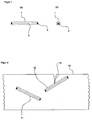
- FIG. 2 shows the concrete bar elements (11) and (13) mixed into a concrete body (10).
- the position of the concrete bar elements results from the mixing and pouring of the concrete.
- the concrete bar elements work evenly in all directions.
- the concrete of the concrete body (10) has already cracked under external load. However, the cracks are stopped by the concrete bar elements because they have a higher tensile strength. There is an increase in the tensile strength of the concrete body.
- Figure 3 shows the state in which the external load has become so great that the crack load of the concrete bar elements (21) has been exceeded.
- the cracks (22) from the concrete body (20) continue in the concrete bar elements (23).
- the full stretch length of the tensioning element (24) comes into effect and there is an increase in the elasticity for the entire concrete body compared to the state without concrete rod elements.
Landscapes
- Engineering & Computer Science (AREA)
- Architecture (AREA)
- Civil Engineering (AREA)
- Structural Engineering (AREA)
- Reinforcement Elements For Buildings (AREA)
- Panels For Use In Building Construction (AREA)
- Rod-Shaped Construction Members (AREA)
- Manufacturing Of Tubular Articles Or Embedded Moulded Articles (AREA)
Applications Claiming Priority (2)
| Application Number | Priority Date | Filing Date | Title |
|---|---|---|---|
| DE4439534A DE4439534A1 (de) | 1994-11-04 | 1994-11-04 | Betonkörper mit Verstärkung |
| DE4439534 | 1994-11-04 |
Publications (2)
| Publication Number | Publication Date |
|---|---|
| EP0712972A1 true EP0712972A1 (fr) | 1996-05-22 |
| EP0712972B1 EP0712972B1 (fr) | 2002-03-06 |
Family
ID=6532553
Family Applications (1)
| Application Number | Title | Priority Date | Filing Date |
|---|---|---|---|
| EP95116996A Expired - Lifetime EP0712972B1 (fr) | 1994-11-04 | 1995-10-27 | Elément en béton armé |
Country Status (2)
| Country | Link |
|---|---|
| EP (1) | EP0712972B1 (fr) |
| DE (2) | DE4439534A1 (fr) |
Cited By (1)
| Publication number | Priority date | Publication date | Assignee | Title |
|---|---|---|---|---|
| DE102015100386A1 (de) * | 2015-01-13 | 2016-07-14 | Technische Universität Dresden | Bewehrungsstab aus Filamentverbund und Verfahren zu dessen Herstellung |
Families Citing this family (2)
| Publication number | Priority date | Publication date | Assignee | Title |
|---|---|---|---|---|
| JP7393816B2 (ja) * | 2022-04-15 | 2023-12-07 | 株式会社I-deate&eng. | 構造基材、構造部材、構造物及び構造部材の構築方法 |
| DE102022132727A1 (de) | 2022-12-08 | 2024-06-13 | H.R. GmbH & Co. KG | Bodenplatte und Verfahren zur Herstellung einer solchen |
Citations (6)
| Publication number | Priority date | Publication date | Assignee | Title |
|---|---|---|---|---|
| US3400507A (en) * | 1966-09-12 | 1968-09-10 | Ellamac Inc | Structural members with preformed concrete reinforcing devices |
| DE2759161A1 (de) * | 1977-12-31 | 1979-07-12 | Strabag Bau Ag | Vorgespannter zugstab aus beton |
| DE2930939A1 (de) * | 1979-07-31 | 1981-02-05 | Heidelberger Zement Ag | Verfahren zum mechanischen verstaerken von formbaren und/oder haertbaren massen, die durch anorganische bindemittel verfestigbar sind |
| US4945694A (en) * | 1989-04-20 | 1990-08-07 | John Mitchell | Building module |
| EP0501879A1 (fr) * | 1991-02-27 | 1992-09-02 | Cogema (Compagnie Generale Des Matieres Nucleaires) | Béton et son procédé de mise en précontrainte, conteneur fabriqué avec ce béton |
| EP0621381A1 (fr) * | 1993-04-22 | 1994-10-26 | Horst Dr.-Ing. Kinkel | Elément d'armature précontraint |
-
1994
- 1994-11-04 DE DE4439534A patent/DE4439534A1/de not_active Withdrawn
-
1995
- 1995-10-27 DE DE59510089T patent/DE59510089D1/de not_active Expired - Fee Related
- 1995-10-27 EP EP95116996A patent/EP0712972B1/fr not_active Expired - Lifetime
Patent Citations (6)
| Publication number | Priority date | Publication date | Assignee | Title |
|---|---|---|---|---|
| US3400507A (en) * | 1966-09-12 | 1968-09-10 | Ellamac Inc | Structural members with preformed concrete reinforcing devices |
| DE2759161A1 (de) * | 1977-12-31 | 1979-07-12 | Strabag Bau Ag | Vorgespannter zugstab aus beton |
| DE2930939A1 (de) * | 1979-07-31 | 1981-02-05 | Heidelberger Zement Ag | Verfahren zum mechanischen verstaerken von formbaren und/oder haertbaren massen, die durch anorganische bindemittel verfestigbar sind |
| US4945694A (en) * | 1989-04-20 | 1990-08-07 | John Mitchell | Building module |
| EP0501879A1 (fr) * | 1991-02-27 | 1992-09-02 | Cogema (Compagnie Generale Des Matieres Nucleaires) | Béton et son procédé de mise en précontrainte, conteneur fabriqué avec ce béton |
| EP0621381A1 (fr) * | 1993-04-22 | 1994-10-26 | Horst Dr.-Ing. Kinkel | Elément d'armature précontraint |
Cited By (1)
| Publication number | Priority date | Publication date | Assignee | Title |
|---|---|---|---|---|
| DE102015100386A1 (de) * | 2015-01-13 | 2016-07-14 | Technische Universität Dresden | Bewehrungsstab aus Filamentverbund und Verfahren zu dessen Herstellung |
Also Published As
| Publication number | Publication date |
|---|---|
| DE59510089D1 (de) | 2002-04-11 |
| DE4439534A1 (de) | 1996-05-09 |
| EP0712972B1 (fr) | 2002-03-06 |
Similar Documents
| Publication | Publication Date | Title |
|---|---|---|
| EP0710313B1 (fr) | Dispositif d'ancrage de cables en materiaux composites a haute performance renforces par des fibres | |
| DE69008803T2 (de) | Faserverstärkter Baustab aus Kunstharz. | |
| DE69929540T2 (de) | Faserverstärktes zementmaterial mit verbesserter zähigkeit und dehnbarkeit | |
| EP0732464B1 (fr) | Procédé de fabrication de revêtements armés, notamment sur des surfaces en béton, et filet d'armature associé | |
| DE60017070T2 (de) | Oberflächenbewehrung für Träger, Säulen, Platten o. d | |
| EP1259679B1 (fr) | Ancrage pour element de traction precontraint et/ou charge et boite d'ancrage | |
| DE2952783A1 (de) | Multiphasen-material mit einer phase aus zement | |
| DE2930939C2 (de) | Verfahren zum mechanischen Verstärken von formbaren und/oder härtbaren Massen | |
| DE102018102317A1 (de) | Endverankerung von Bewehrungsfasern | |
| DE2322271C2 (de) | Verfahren zum mechanischen Verstärken von formbaren und/oder härtbaren Massen | |
| EP0712972B1 (fr) | Elément en béton armé | |
| DE102016111176A1 (de) | Betonbewehrungsgitterelement, Verfahren zu dessen Herstellung sowie dessen Verwendung | |
| DE19525508A1 (de) | Verfahren zur Ertüchtigung von Bauteilen aus Stahlbeton oder Mauerwerk und Verwendung einer besonderen Laminatbeschichtung für die Ertüchtigung | |
| EP1282751B1 (fr) | Fibres d'acier | |
| EP0895558B1 (fr) | Barre d'armature | |
| DE2705483C2 (fr) | ||
| DE10039830B4 (de) | Verwendung von ringförmigen Faserverbundwerkstoffen als Bewehrungselemente in Beton | |
| DE102006038130B3 (de) | Verfahren zur Herstellung tragender Strukturen und tragende Struktur | |
| DE2504122B2 (de) | Im spannbett vorgespanntes bauteil aus stahlbeton | |
| WO2008095211A1 (fr) | Corps en forme de disque destinés à des fibres | |
| DE69602266T2 (de) | Bauelement für brücken und boden | |
| WO1998032934A1 (fr) | Bande plate lamellaire et son utilisation pour renforcer des elements de construction | |
| EP3947844B1 (fr) | Corps en beton precontraint, son procédé de production et son utilisation | |
| DE102023001132A1 (de) | Betonbewehrungsgitterelement und Bauteil | |
| DE102021115774A1 (de) | Vorrichtung und Verfahren zur Herstellung eines flächigen Bauteils mit vorgespannter textiler Bewehrung |
Legal Events
| Date | Code | Title | Description |
|---|---|---|---|
| PUAI | Public reference made under article 153(3) epc to a published international application that has entered the european phase |
Free format text: ORIGINAL CODE: 0009012 |
|
| AK | Designated contracting states |
Kind code of ref document: A1 Designated state(s): DE FR GB |
|
| 17P | Request for examination filed |
Effective date: 19961121 |
|
| 17Q | First examination report despatched |
Effective date: 19990907 |
|
| GRAG | Despatch of communication of intention to grant |
Free format text: ORIGINAL CODE: EPIDOS AGRA |
|
| GRAG | Despatch of communication of intention to grant |
Free format text: ORIGINAL CODE: EPIDOS AGRA |
|
| GRAH | Despatch of communication of intention to grant a patent |
Free format text: ORIGINAL CODE: EPIDOS IGRA |
|
| GRAH | Despatch of communication of intention to grant a patent |
Free format text: ORIGINAL CODE: EPIDOS IGRA |
|
| REG | Reference to a national code |
Ref country code: GB Ref legal event code: IF02 |
|
| GRAA | (expected) grant |
Free format text: ORIGINAL CODE: 0009210 |
|
| AK | Designated contracting states |
Kind code of ref document: B1 Designated state(s): DE FR GB |
|
| REF | Corresponds to: |
Ref document number: 59510089 Country of ref document: DE Date of ref document: 20020411 |
|
| GBT | Gb: translation of ep patent filed (gb section 77(6)(a)/1977) |
Effective date: 20020516 |
|
| ET | Fr: translation filed | ||
| PG25 | Lapsed in a contracting state [announced via postgrant information from national office to epo] |
Ref country code: GB Free format text: LAPSE BECAUSE OF NON-PAYMENT OF DUE FEES Effective date: 20021027 |
|
| PLBE | No opposition filed within time limit |
Free format text: ORIGINAL CODE: 0009261 |
|
| STAA | Information on the status of an ep patent application or granted ep patent |
Free format text: STATUS: NO OPPOSITION FILED WITHIN TIME LIMIT |
|
| 26N | No opposition filed |
Effective date: 20021209 |
|
| PG25 | Lapsed in a contracting state [announced via postgrant information from national office to epo] |
Ref country code: DE Free format text: LAPSE BECAUSE OF NON-PAYMENT OF DUE FEES Effective date: 20030501 |
|
| GBPC | Gb: european patent ceased through non-payment of renewal fee | ||
| PG25 | Lapsed in a contracting state [announced via postgrant information from national office to epo] |
Ref country code: FR Free format text: LAPSE BECAUSE OF NON-PAYMENT OF DUE FEES Effective date: 20030630 |
|
| REG | Reference to a national code |
Ref country code: FR Ref legal event code: ST |