EP0712978B1 - Mécanisme de couplage d'une serrure à double cylindre - Google Patents
Mécanisme de couplage d'une serrure à double cylindre Download PDFInfo
- Publication number
- EP0712978B1 EP0712978B1 EP95115130A EP95115130A EP0712978B1 EP 0712978 B1 EP0712978 B1 EP 0712978B1 EP 95115130 A EP95115130 A EP 95115130A EP 95115130 A EP95115130 A EP 95115130A EP 0712978 B1 EP0712978 B1 EP 0712978B1
- Authority
- EP
- European Patent Office
- Prior art keywords
- coupling
- pin
- wall
- opening
- Prior art date
- Legal status (The legal status is an assumption and is not a legal conclusion. Google has not performed a legal analysis and makes no representation as to the accuracy of the status listed.)
- Expired - Lifetime
Links
- 230000008878 coupling Effects 0.000 title claims abstract description 108
- 238000010168 coupling process Methods 0.000 title claims abstract description 108
- 238000005859 coupling reaction Methods 0.000 title claims abstract description 108
- 230000015572 biosynthetic process Effects 0.000 claims abstract description 4
- 238000003780 insertion Methods 0.000 claims description 32
- 230000037431 insertion Effects 0.000 claims description 32
- 238000006073 displacement reaction Methods 0.000 claims description 3
- 230000002093 peripheral effect Effects 0.000 claims 1
- 125000006850 spacer group Chemical group 0.000 description 11
- 230000006835 compression Effects 0.000 description 7
- 238000007906 compression Methods 0.000 description 7
- 230000001427 coherent effect Effects 0.000 description 2
- 238000011161 development Methods 0.000 description 2
- 230000018109 developmental process Effects 0.000 description 2
- 238000009434 installation Methods 0.000 description 2
- 230000004323 axial length Effects 0.000 description 1
- 238000005516 engineering process Methods 0.000 description 1
- 230000001771 impaired effect Effects 0.000 description 1
- 238000004519 manufacturing process Methods 0.000 description 1
- 210000002435 tendon Anatomy 0.000 description 1
- 230000007704 transition Effects 0.000 description 1
- 238000011144 upstream manufacturing Methods 0.000 description 1
Images





Classifications
-
- E—FIXED CONSTRUCTIONS
- E05—LOCKS; KEYS; WINDOW OR DOOR FITTINGS; SAFES
- E05B—LOCKS; ACCESSORIES THEREFOR; HANDCUFFS
- E05B17/00—Accessories in connection with locks
- E05B17/04—Devices for coupling the turning cylinder of a single or a double cylinder lock with the bolt operating member
- E05B17/047—Devices for coupling the turning cylinder of a single or a double cylinder lock with the bolt operating member with rotating output elements forming part of cylinder locks, e.g. locking cams of double cylinder locks
-
- E—FIXED CONSTRUCTIONS
- E05—LOCKS; KEYS; WINDOW OR DOOR FITTINGS; SAFES
- E05B—LOCKS; ACCESSORIES THEREFOR; HANDCUFFS
- E05B9/00—Lock casings or latch-mechanism casings ; Fastening locks or fasteners or parts thereof to the wing
- E05B9/10—Coupling devices for the two halves of double cylinder locks, e.g. devices for coupling the rotor with the locking cam
- E05B9/105—Coupling devices for the two halves of double cylinder locks, e.g. devices for coupling the rotor with the locking cam including disengagement means, e.g. opening from one side being still possible even if the key is inserted from the other side
Definitions
- the invention relates to a coupling device for use in a Double locking cylinder, with a locking link hub and with two bound to each other by means of a plug connection Coupling parts in an opening of a Closing member hub middle wall, which opening both sides of an annular wall of the locking member hub is included, to form the connector one coupling part a pin and the other Coupling part a radially open pocket for receiving the Has pin, which with an outer wall Rib to an inner-walled, radially open recess the bag is in such a way that the radial pluggable coupling parts to each other and to Lock member hub when attacking a key tip one of the outer surfaces of one of the coupling parts are axially displaceable.
- a coupling device of the type in question is known from DE-OS 42 42 522, the radial connector of the two coupling parts to each other in this way is solved that the one coupling part through a recess into the pocket in the ring wall of the locking link hub the other coupling part is insertable.
- the coupling part having the pocket inserted in the opening of the closing member hub middle wall.
- the plug connection After the plug connection has been carried out take the coupling parts their functional position on. It gets plugged together the coupling parts the locking member hub in this connector included so that after plugging together the coupling parts with the locking member hub form a coherent unit.
- This unit is in the simplest way in a double locking cylinder inserted.
- the object of the present invention is a coupling device of the type in question in such a way that the two coupling parts are each radial are secured against falling out and that the coupling parts from both sides of the closing member hub middle wall are plugged in here.
- the coupling part used opposite side of the middle wall Position the second at an angle to the radial Coupling part such that the radially open recess the pocket of the pocket part the rib on the outside wall of the pin part.
- To form the plug connection follows an inward slant to the radial Insertion movement of a coupling part Tilt shift in the perpendicular to the coupling axis trending level. Slide-in movement and tilt shift can also be overlaid.
- Plug connection take the coupling parts their functional Position. It will coincide with that Assemble the coupling parts of the locking member hub included in this connector, so that after Put the coupling parts together with the locking member hub formed a coherent unit is.
- Both coupling parts are of one, none Openings or the like having ring wall Closing member hub includes, with which the coupling parts radially are secured.
- To form the plug connection is directed inwards at an angle to the radial Insertion movement guided the pocket part in such a way that first the outside wall rib of the pin in the pocket's radially open recess becomes. This is followed by another radially inward directed movement of the pocket part up to the outer wall of the pocket part the area of the ring wall Closing link hub leaves and thus a tilt shift of the pocket part can be done. Throughout the entire Insertion movement and the tilting displacement leaves the outside wall-side rib of the pin does not have the rear grip to the inner-walled, radially open recess of the bag, in which area to form a backhand Provide the bag with a web pointing inwards is.
- the pocket part can eventually be parallel to the specified level, d. H. moved radially further until the pin part is completely in the radially open pocket of the pocket part lies. In this position is axially secured by that the outer wall-side rib of the pin part too the inner-walled, radially open recess of the pocket part stands behind, for what in the area of radial open recess of the pocket part of the latter with a corresponding to the outer wall-side rib of the pin part Bridge is provided.
- the mentioned axial Fuse refers to the entire structural unit of the Coupling device.
- the connector can also be given in that in a known manner between the two coupling parts a coaxially arranged compression coil spring is.
- the front edge of the pocket wall is rounded Forms skid, which leads to the entrance of the connector easy insertion of the rib on the outside wall of the pin part in the radially open recess of the Pocket part is given.
- the axial opening width of the radial Pocket opening is dimensioned such that the rib in of the angled position. Throughout the entire diagonal to the radial The insertion movement of the pocket part is the latter in an angled position to the pin part. It it is preferred that the rib of the pin part already at the beginning of the insertion movement into the radially open one Bag enters.
- the opening width the radial pocket opening should be such that the rib throughout the diagonal to the radial Insert movement in the pocket opening takes place without tilting there.
- the so dimensioned axial opening width of the pocket opening continues to offer the axial displaceability of the coupling parts relative to one another, limited by the rear grip.
- the rib of the pin part position that the rib only after a complete Insertion movement directed obliquely to the radial and a subsequent tipping shift in the pocket opening engages. Will after the tipping shift the pocket part further radially into the functional The position is shifted, so is the rear grip the rib to the web of the pocket part is formed.
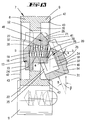
- a double profile cylinder 1 This has a cylinder housing 2 consisting of a cylindrical section A and a radially projecting to it Flange section B.
- the cylindrical section A is interrupted by a central cutout 3, which continues into the flange section B. leaving a connecting bridge between the two cylinder halves created thereby.
- An opening 12 is recessed in the hub center wall 10. Their outline corresponds to a circle two tendons lying on both sides, parallel to each other.
- a coupling part 13 is form-fitting in the opening 12 inserted. This is in turn in a plug connection with another coupling part 14.
- Both Coupling parts 13, 14 are with surfaces lying outwards provided, which of end plates 15, 16 are formed. With these, the coupling parts protrude into assigned to them pot-like recesses 17 of the facing Cylinder core ends.
- Each plate 15, 16 has a central, outward elevation 18, about which they are at the bottom of the respective blind hole 17th supports. The support is effected by both Coupling parts 13, 14 spreading compression spring 19th
- the Coupling parts 13, 14 Before assembling the double profile cylinder 1 form the Coupling parts 13, 14 with the locking member hub 7 a contiguous unit. Because the front plates 15, 16 with a partial length of its edge the opening 12 protrude from the hub center wall 10, the coupling parts 13, 14 not except by axial displacement Engagement to the opening 12 are brought. The corresponding Partial lengths of the edge then act on the Opening 12 adjacent area of the hub center wall 10.
- the coupling part 14 designed as a pocket part has one, viewed in the installation position, runs vertically Pocket 20, the insertion end of which is radially open and whose end facing away from the insertion direction is closed is. Furthermore, the pocket 20 is on the other Coupling part 13 facing end open.
- the pocket 20 forms a dovetail guide for outwards protruding ribs 21 of the pin part Coupling part 13. The ribs 21 are supported doing so on inwardly directed webs 22 of the dovetail guide and limit the pressure spring 19 spread apart of the coupling parts 13, 14.
- the axial opening width w between the webs 22 and the end of the pocket facing away from the insertion direction 20 formed radial pocket opening 23 is larger dimensioned as that, also viewed in the axial direction, Width r of the ribs 21 of the pin part 13.
- Es can be a ratio of opening width w to Rib width r from 3: 1 to 5: 1, preferably 4: 1, be given. It is such an axial game between the Coupling parts 13, 14 created. Because of that can the coupling parts 13, 14 against the force of Compression spring 19 to be shifted towards each other. In order to this opposite movement by the compression spring 19 is not impaired, it lies in one end a central bore 24 of the coupling part 13. The other end gets centered in one with the Bore 24, recess 25 aligned in the installation position of the coupling part 14.
- the compression spring 19 is used for Securing the assembled position of the coupling parts 13, 14 including the locking member hub 7.
- the end faces of the plates 15, 16 have open insertion slanted slots 26, 27 for the key tip 28 of a key 29.
- the surface F3 of the groove 27, however, is arranged and forms continuously on the pin part 13 with the area F2 a roof shape.
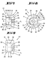
- the pocket part 14 shown in FIGS. 7 to 9 essentially consists of one of the hub center wall opening 12 correspondingly trained cross section having coupling body 30 and the already mentioned Plate 16 together, the latter coaxial with that Coupling body 30 arranged on the same material is.
- the coupling body 30 is with the mentioned provided radially open pocket 20, which is in a radial Extension starting from the area open to the edge to the diametrically opposite area of the Coupling body extends, leaving a pocket bottom 31.
- the pocket 20 In the area of this pocket bottom 31 the pocket 20 is semicircular in cross section. Both sides of the pocket 20 are in the direction of Pocket part axis a considered, pocket walls 32 formed.
- the pocket 20 is also axial Considered direction, open-ended, and to the side facing plate 16.
- the pocket part 14 has the two in this opening area opposing, inwardly directed webs 22 on. The latter are of the same material in the relevant Formed end regions of the pocket walls 32.
- the pocket extends in the axial direction 20 starting from the open edge area into the area the transition from the coupling body 30 to the plate 16 leaving a distance between them.
- the Ratio between the axial length of the coupling body 30 and the corresponding depth of the pocket 20 is about 5: 2 to 5: 4, preferably 5: 3.
- pocket opening 23 The between the of the pocket part end face 35th opposite sides of the webs 22 and the opening limit forming pocket back 34 is formed space referred to as pocket opening 23.
- inward bevels 37 are provided in the area of the front edges 36 of the pocket walls 32 inward bevels 37 are provided.
- the front edges the webs 22 are designed accordingly (cf. in particular FIGS. 7 and 8).
- the pocket back 34 is in the radial opening area a sliding edge 39 which is located between the Chamfer 37 of the pocket wall end edges 36 extends.
- This sliding edge 39 can also be designed as a chamfer.
- the pin part 13 shown in FIGS. 10 to 12 sets essentially from the plate 15 already mentioned and one of the pockets 20 correspondingly shaped pin 40 together. At the opposite of the plate 15 The end of the pin 40 on both sides of its axis b perpendicular to this aligned ribs 21.
- the coupling part 13 or the pin part inserted into the opening 12 of the hub center wall 10. Limited is the insertion through the two partial lengths the edge of the plate 15, see in particular FIG. 5.
- the pin part 13 projects with its Pin 40 out of the opening 12, this on the Plate 15 of the pin part 13 opposite side the hub center wall 10.
- the at the free end of the Pins 40 arranged ribs 21 are thus exposed accessible in the interior of the side facing this page Ring wall 8. It does not matter which side the pin part 13 is inserted into the opening 12.
- the Pocket part 14 is aligned so that the the pocket back 34 arranged sliding edge 39 on the Pin end face 41 slides. Furthermore, the Skids 38 of the pocket wall end edges 36 on the the pocket part 14 facing surface of the pin part plate 15 slide. There is no canting here and therefore no interference with the linearly aligned Insertion movement of the pocket part 14.
- Advantageously has the pocket part 14 facing Ring wall 8 on its inner edge 42 a chamfer 43, over which during the linear insertion movement the Pocket part 14 can slide away.
- the linear direction of movement B of the pocket part 14 runs approximately at an angle beta of 15 to 45 ° to Radials, preferably 30 °.
- the angle alpha between the two axes a and b of the pocket part 14 and the Pin part 13 corresponds to the size of the angle beta.
- the compression spring 19 is already in the bore 24 of the coupling part 13 has been inserted.
- the plug 15 and 16 are aligned the coupling parts 13 and 14 with each other.
- This present The unit as a whole can be the locking cylinder assigned, in the area of the cutout 3.
- the plates 15 and 16 grip when inserting the Cylinder cores 5 and 6 in the blind bores 17 of the cylinder core ends on.
- the cylinder cores 5 are secured and 6 in the axial direction through the ring wall 8 on both sides running snap rings 44.
- a resolution of the described unit can only willful because of a tilting of the Pocket part 14 follow a linear extension movement got to.
- the coupling parts 13 and 14 are accordingly Formation of the connector in both axial and secured in the radial direction against falling out.
- a spacer 45 is shown in FIGS. which with asymmetrically designed double profile cylinders 1 is used.
- Such one Double profile cylinder 1 has different leg lengths of the cylinder halves.
- This double profile cylinder 1 from both sides, d. H. by means of the cylinder core 5 or 6 with a key to operate, said spacer 45 in the area the recess 17 of a cylinder core 5 or 6 inserted.
- the spacer is in the key insertion direction 45 in the exemplary embodiment shown in FIG. 17 upstream of the coupling part 14.
- the axial The length of the spacer 45 corresponds to the leg length difference between the two cylinder halves.
- the spacer 45 consists essentially of one circularly shaped cylinder body 46, the outer diameter that of the coupling parts 13 and 14 corresponds. On which is the end face 47 facing the coupling part 14 a circular recess 48 is provided for receiving the elevation 18 of the coupling part 14. From the previously called end face 47 is a radially aligned Coupling nose 49 with which the spacer 45 in installed condition with positive rotation the coupling part 14 stands by the coupling lug 49 enters the insertion slant slot 26. The coupling nose 49 corresponds to the insertion slant slot 26 molded. On the face 47 facing away from the end face On the side, the spacer 45 has an insertion slot 26 of the coupling part 14 accordingly trained insertion groove 50, in which upon key actuation the key tip 28 engages positively.
- a rotary movement of the key 29 causes positive rotational driving a twisting of the coupling part 14 and thus also the closing member hub 7.
- the spacer 45 described above is also the same Design can be assigned to the coupling part 13.
Landscapes
- Engineering & Computer Science (AREA)
- Mechanical Engineering (AREA)
- Snaps, Bayonet Connections, Set Pins, And Snap Rings (AREA)
- Lock And Its Accessories (AREA)
- Flanged Joints, Insulating Joints, And Other Joints (AREA)
- Mechanical Operated Clutches (AREA)
Claims (6)
- Dispositif d'accouplement destiné à être utilisé dans un cylindre de serrure double (1), présentant un moyeu de serrure (7) et deux pièces d'accouplement (13, 14) reliées l'une à l'autre par une liaison à enfichage et qui sont disposées dans une ouverture (12) d'une paroi médiane (10) du moyeu de serrure, laquelle ouverture (12) est entourée sur chacune de ses deux faces d'une paroi annulaire (8) du moyeu de serrure (7), l'une (13) des pièces d'accouplement comportant un têton (40) et l'autre (14) des pièces d'accouplement comportant une poche (20) ouverte radialement et destinée à recevoir le têton (40) pour réaliser la liaison par enfichage, la poche venant s'accrocher par l'arrière avec une nervure (21) située du côté de la paroi extérieure dans une cavité de la poche (20) ouverte radialement sur la paroi intérieure, de telle façon que les pièces d'accouplement (13, 14) susceptibles d'être enfichées radialement l'une dans l'autre, soient susceptibles de coulisser axialement l'une par rapport à l'autre et par rapport au moyeu de serrure (7) sous l'action d'une pointe de clé (28) sur l'une des surfaces située vers l'extérieur des pièces d'accouplement, caractérisé en ce qu'au début de la liaison à enfichage, un déplacement d'insertion en biais par rapport aux radiales et dirigé vers l'intérieur suit un changement de position par basculement d'une pièce d'accouplement (14).
- Dispositif d'accouplement selon la revendication 1, caractérisé en ce que la pièce d'accouplement (14) présentant la poche (20) est susceptible de pivoter angulairement sur le têton (40) de la pièce à têton (13).
- Dispositif d'accouplement selon l'une ou plusieurs des revendications précédentes, caractérisé en ce que, pour réaliser le trajet de déplacement du déplacement d'insertion se développant en biais par rapport aux radiales, l'arête intérieure de bord (42) de la paroi annulaire (8) et/ou l'arête frontale (36) de la paroi (32) de la poche présent(ent) un chanfrein ou facette (37, 43).
- Dispositif d'accouplement selon l'une ou plusieurs des revendications précédentes, caractérisé en ce que l'arête frontale (36) de la paroi (32) de la poche présente un patin de glissement arrondi (38).
- Dispositif d'accouplement selon l'une ou plusieurs des revendications précédentes, caractérisé en ce que la largeur axiale d'ouverture (w) de l'ouverture radiale de poche (23) est dimensionnée de telle façon que la nervure (21) trouve sa place à l'intérieur, en position basculée angulairement.
- Dispositif d'accouplement selon l'une ou plusieurs des revendications précédentes, caractérisé par une arête de glissement (39) ou un chanfrein, associé(e) à la délimitation (34) de l'ouverture de poche située à l'opposé de la nervure ou partie en saillie (22), cette arête glissant sur la surface frontale (41) du têton au cours du pivotement angulaire de la partie de poche (14).
Applications Claiming Priority (2)
| Application Number | Priority Date | Filing Date | Title |
|---|---|---|---|
| DE4440737 | 1994-11-15 | ||
| DE4440737A DE4440737A1 (de) | 1994-11-15 | 1994-11-15 | Kupplungseinrichtung in Doppel-Schließzylindern |
Publications (2)
| Publication Number | Publication Date |
|---|---|
| EP0712978A1 EP0712978A1 (fr) | 1996-05-22 |
| EP0712978B1 true EP0712978B1 (fr) | 1999-04-21 |
Family
ID=6533355
Family Applications (1)
| Application Number | Title | Priority Date | Filing Date |
|---|---|---|---|
| EP95115130A Expired - Lifetime EP0712978B1 (fr) | 1994-11-15 | 1995-09-26 | Mécanisme de couplage d'une serrure à double cylindre |
Country Status (3)
| Country | Link |
|---|---|
| EP (1) | EP0712978B1 (fr) |
| AT (1) | ATE179235T1 (fr) |
| DE (2) | DE4440737A1 (fr) |
Families Citing this family (1)
| Publication number | Priority date | Publication date | Assignee | Title |
|---|---|---|---|---|
| DE102007000203A1 (de) | 2007-04-04 | 2008-10-09 | Aug. Winkhaus Gmbh & Co. Kg | Schließzylinder |
Family Cites Families (1)
| Publication number | Priority date | Publication date | Assignee | Title |
|---|---|---|---|---|
| DE4242522C2 (de) | 1992-12-16 | 1996-05-02 | Wilka Schliestechnik Gmbh | Kupplungseinrichtung in Doppel-Schließzylindern |
-
1994
- 1994-11-15 DE DE4440737A patent/DE4440737A1/de not_active Withdrawn
-
1995
- 1995-09-26 DE DE59505703T patent/DE59505703D1/de not_active Expired - Fee Related
- 1995-09-26 AT AT95115130T patent/ATE179235T1/de not_active IP Right Cessation
- 1995-09-26 EP EP95115130A patent/EP0712978B1/fr not_active Expired - Lifetime
Also Published As
| Publication number | Publication date |
|---|---|
| DE59505703D1 (de) | 1999-05-27 |
| EP0712978A1 (fr) | 1996-05-22 |
| DE4440737A1 (de) | 1996-05-23 |
| ATE179235T1 (de) | 1999-05-15 |
Similar Documents
| Publication | Publication Date | Title |
|---|---|---|
| EP1350909B1 (fr) | Clé pour serrures à barillet | |
| DE4414518C2 (de) | Schließzylinder und Flachschlüssel hierzu | |
| DE2317771C3 (de) | Vorrichtung zum Verstellen des Einstellgeheimnisses in einem Permutations-Vorhängeschloß mit Schwenkschiebebügel | |
| DE69415534T2 (de) | Wiederverwendbares siegel für einen stab | |
| DE3225952C2 (fr) | ||
| DE3715972C2 (de) | Kupplungseinrichtung an Doppel-Schließzylindern | |
| DE2833453A1 (de) | Magnetschloss | |
| DE69904408T2 (de) | Schlüssel mit bewegbarem stift, sicherheitsdrehzylinder und damit ausgerüstetes schloss | |
| DE3535426C2 (de) | Kupplungseinrichtung in einem Doppelschließzylinder | |
| DE3629608A1 (de) | Elektrischer mehrfachsteckverbinder | |
| DE202016003806U1 (de) | Schlüssel für einen Schließzylinder und Schließvorrichtung | |
| EP0364660A2 (fr) | Serrure cylindrique | |
| DE3836872C2 (de) | Aus Flachschlüssel und Schließzylinder bestehende Schließvorrichtung | |
| AT405960B (de) | Schliesszylinder | |
| DE69202953T2 (de) | Zylinderschloss. | |
| EP0712978B1 (fr) | Mécanisme de couplage d'une serrure à double cylindre | |
| DE4242522C2 (de) | Kupplungseinrichtung in Doppel-Schließzylindern | |
| DE9402519U1 (de) | Kupplungseinrichtung in einem Doppelschließzylinder mit Gefahrenfunktion | |
| EP0118910B1 (fr) | Cylindre de fermeture | |
| EP0052803A2 (fr) | Bras de charnière ayant une plaque de montage | |
| DE2640956A1 (de) | Zylinderschloss | |
| DE3521530C2 (fr) | ||
| DE4412056C2 (de) | Kabelschloß | |
| DE19640581A1 (de) | Spreizdübel | |
| CH636400A5 (en) | Rotary cylinder lock with radial spring-loaded tumbler pins and with axially displaceable sliding pins |
Legal Events
| Date | Code | Title | Description |
|---|---|---|---|
| PUAI | Public reference made under article 153(3) epc to a published international application that has entered the european phase |
Free format text: ORIGINAL CODE: 0009012 |
|
| AK | Designated contracting states |
Kind code of ref document: A1 Designated state(s): AT BE CH DE DK ES FR IT LI NL PT |
|
| 17P | Request for examination filed |
Effective date: 19960716 |
|
| GRAG | Despatch of communication of intention to grant |
Free format text: ORIGINAL CODE: EPIDOS AGRA |
|
| GRAG | Despatch of communication of intention to grant |
Free format text: ORIGINAL CODE: EPIDOS AGRA |
|
| GRAH | Despatch of communication of intention to grant a patent |
Free format text: ORIGINAL CODE: EPIDOS IGRA |
|
| 17Q | First examination report despatched |
Effective date: 19980925 |
|
| GRAH | Despatch of communication of intention to grant a patent |
Free format text: ORIGINAL CODE: EPIDOS IGRA |
|
| GRAA | (expected) grant |
Free format text: ORIGINAL CODE: 0009210 |
|
| AK | Designated contracting states |
Kind code of ref document: B1 Designated state(s): AT BE CH DE DK ES FR IT LI NL PT |
|
| PG25 | Lapsed in a contracting state [announced via postgrant information from national office to epo] |
Ref country code: IT Free format text: LAPSE BECAUSE OF FAILURE TO SUBMIT A TRANSLATION OF THE DESCRIPTION OR TO PAY THE FEE WITHIN THE PRE;WARNING: LAPSES OF ITALIAN PATENTS WITH EFFECTIVE DATE BEFORE 2007 MAY HAVE OCCURRED AT ANY TIME BEFORE 2007. THE CORRECT EFFECTIVE DATE MAY BE DIFFERENT FROM THE ONE RECORDED.SCRIBED TIME-LIMIT Effective date: 19990421 Ref country code: FR Free format text: LAPSE BECAUSE OF FAILURE TO SUBMIT A TRANSLATION OF THE DESCRIPTION OR TO PAY THE FEE WITHIN THE PRESCRIBED TIME-LIMIT Effective date: 19990421 Ref country code: ES Free format text: THE PATENT HAS BEEN ANNULLED BY A DECISION OF A NATIONAL AUTHORITY Effective date: 19990421 |
|
| REF | Corresponds to: |
Ref document number: 179235 Country of ref document: AT Date of ref document: 19990515 Kind code of ref document: T |
|
| REG | Reference to a national code |
Ref country code: CH Ref legal event code: NV Representative=s name: R. A. EGLI & CO. PATENTANWAELTE Ref country code: CH Ref legal event code: EP |
|
| REF | Corresponds to: |
Ref document number: 59505703 Country of ref document: DE Date of ref document: 19990527 |
|
| PG25 | Lapsed in a contracting state [announced via postgrant information from national office to epo] |
Ref country code: DK Free format text: LAPSE BECAUSE OF FAILURE TO SUBMIT A TRANSLATION OF THE DESCRIPTION OR TO PAY THE FEE WITHIN THE PRESCRIBED TIME-LIMIT Effective date: 19990721 |
|
| PG25 | Lapsed in a contracting state [announced via postgrant information from national office to epo] |
Ref country code: PT Free format text: LAPSE BECAUSE OF FAILURE TO SUBMIT A TRANSLATION OF THE DESCRIPTION OR TO PAY THE FEE WITHIN THE PRESCRIBED TIME-LIMIT Effective date: 19990723 |
|
| EN | Fr: translation not filed | ||
| PG25 | Lapsed in a contracting state [announced via postgrant information from national office to epo] |
Ref country code: BE Free format text: LAPSE BECAUSE OF NON-PAYMENT OF DUE FEES Effective date: 19990930 |
|
| PLBE | No opposition filed within time limit |
Free format text: ORIGINAL CODE: 0009261 |
|
| STAA | Information on the status of an ep patent application or granted ep patent |
Free format text: STATUS: NO OPPOSITION FILED WITHIN TIME LIMIT |
|
| BERE | Be: lapsed |
Owner name: WILKA SCHLIESSTECHNIK G.M.B.H. Effective date: 19990930 |
|
| 26N | No opposition filed | ||
| PGFP | Annual fee paid to national office [announced via postgrant information from national office to epo] |
Ref country code: AT Payment date: 20000816 Year of fee payment: 6 |
|
| PGFP | Annual fee paid to national office [announced via postgrant information from national office to epo] |
Ref country code: CH Payment date: 20000821 Year of fee payment: 6 |
|
| PG25 | Lapsed in a contracting state [announced via postgrant information from national office to epo] |
Ref country code: AT Free format text: LAPSE BECAUSE OF NON-PAYMENT OF DUE FEES Effective date: 20010926 |
|
| PG25 | Lapsed in a contracting state [announced via postgrant information from national office to epo] |
Ref country code: LI Free format text: LAPSE BECAUSE OF NON-PAYMENT OF DUE FEES Effective date: 20010930 Ref country code: CH Free format text: LAPSE BECAUSE OF NON-PAYMENT OF DUE FEES Effective date: 20010930 |
|
| REG | Reference to a national code |
Ref country code: CH Ref legal event code: PL |
|
| PGFP | Annual fee paid to national office [announced via postgrant information from national office to epo] |
Ref country code: NL Payment date: 20080908 Year of fee payment: 14 |
|
| PGFP | Annual fee paid to national office [announced via postgrant information from national office to epo] |
Ref country code: DE Payment date: 20080905 Year of fee payment: 14 |
|
| REG | Reference to a national code |
Ref country code: NL Ref legal event code: V1 Effective date: 20100401 |
|
| PG25 | Lapsed in a contracting state [announced via postgrant information from national office to epo] |
Ref country code: NL Free format text: LAPSE BECAUSE OF NON-PAYMENT OF DUE FEES Effective date: 20100401 Ref country code: DE Free format text: LAPSE BECAUSE OF NON-PAYMENT OF DUE FEES Effective date: 20100401 |