EP0713023A1 - Accouplement d'arbres - Google Patents
Accouplement d'arbres Download PDFInfo
- Publication number
- EP0713023A1 EP0713023A1 EP95114424A EP95114424A EP0713023A1 EP 0713023 A1 EP0713023 A1 EP 0713023A1 EP 95114424 A EP95114424 A EP 95114424A EP 95114424 A EP95114424 A EP 95114424A EP 0713023 A1 EP0713023 A1 EP 0713023A1
- Authority
- EP
- European Patent Office
- Prior art keywords
- pin
- bolt
- shaft
- sleeve
- piston
- Prior art date
- Legal status (The legal status is an assumption and is not a legal conclusion. Google has not performed a legal analysis and makes no representation as to the accuracy of the status listed.)
- Granted
Links
- 230000008878 coupling Effects 0.000 title claims abstract description 23
- 238000010168 coupling process Methods 0.000 title claims abstract description 23
- 238000005859 coupling reaction Methods 0.000 title claims abstract description 23
- 230000006835 compression Effects 0.000 description 3
- 238000007906 compression Methods 0.000 description 3
- 230000005540 biological transmission Effects 0.000 description 2
- 238000010276 construction Methods 0.000 description 1
- 238000009434 installation Methods 0.000 description 1
Images

Classifications
-
- F—MECHANICAL ENGINEERING; LIGHTING; HEATING; WEAPONS; BLASTING
- F16—ENGINEERING ELEMENTS AND UNITS; GENERAL MEASURES FOR PRODUCING AND MAINTAINING EFFECTIVE FUNCTIONING OF MACHINES OR INSTALLATIONS; THERMAL INSULATION IN GENERAL
- F16D—COUPLINGS FOR TRANSMITTING ROTATION; CLUTCHES; BRAKES
- F16D1/00—Couplings for rigidly connecting two coaxial shafts or other movable machine elements
- F16D1/10—Quick-acting couplings in which the parts are connected by simply bringing them together axially
-
- B—PERFORMING OPERATIONS; TRANSPORTING
- B41—PRINTING; LINING MACHINES; TYPEWRITERS; STAMPS
- B41F—PRINTING MACHINES OR PRESSES
- B41F13/00—Common details of rotary presses or machines
- B41F13/008—Mechanical features of drives, e.g. gears, clutches
-
- F—MECHANICAL ENGINEERING; LIGHTING; HEATING; WEAPONS; BLASTING
- F16—ENGINEERING ELEMENTS AND UNITS; GENERAL MEASURES FOR PRODUCING AND MAINTAINING EFFECTIVE FUNCTIONING OF MACHINES OR INSTALLATIONS; THERMAL INSULATION IN GENERAL
- F16D—COUPLINGS FOR TRANSMITTING ROTATION; CLUTCHES; BRAKES
- F16D1/00—Couplings for rigidly connecting two coaxial shafts or other movable machine elements
- F16D1/10—Quick-acting couplings in which the parts are connected by simply bringing them together axially
- F16D1/108—Quick-acting couplings in which the parts are connected by simply bringing them together axially having retaining means rotating with the coupling and acting by interengaging parts, i.e. positive coupling
-
- F—MECHANICAL ENGINEERING; LIGHTING; HEATING; WEAPONS; BLASTING
- F16—ENGINEERING ELEMENTS AND UNITS; GENERAL MEASURES FOR PRODUCING AND MAINTAINING EFFECTIVE FUNCTIONING OF MACHINES OR INSTALLATIONS; THERMAL INSULATION IN GENERAL
- F16B—DEVICES FOR FASTENING OR SECURING CONSTRUCTIONAL ELEMENTS OR MACHINE PARTS TOGETHER, e.g. NAILS, BOLTS, CIRCLIPS, CLAMPS, CLIPS OR WEDGES; JOINTS OR JOINTING
- F16B2200/00—Constructional details of connections not covered for in other groups of this subclass
- F16B2200/69—Redundant disconnection blocking means
-
- Y—GENERAL TAGGING OF NEW TECHNOLOGICAL DEVELOPMENTS; GENERAL TAGGING OF CROSS-SECTIONAL TECHNOLOGIES SPANNING OVER SEVERAL SECTIONS OF THE IPC; TECHNICAL SUBJECTS COVERED BY FORMER USPC CROSS-REFERENCE ART COLLECTIONS [XRACs] AND DIGESTS
- Y10—TECHNICAL SUBJECTS COVERED BY FORMER USPC
- Y10T—TECHNICAL SUBJECTS COVERED BY FORMER US CLASSIFICATION
- Y10T403/00—Joints and connections
- Y10T403/57—Distinct end coupler
- Y10T403/5706—Diverse serial connections
- Y10T403/5713—Axially cleft coupler
-
- Y—GENERAL TAGGING OF NEW TECHNOLOGICAL DEVELOPMENTS; GENERAL TAGGING OF CROSS-SECTIONAL TECHNOLOGIES SPANNING OVER SEVERAL SECTIONS OF THE IPC; TECHNICAL SUBJECTS COVERED BY FORMER USPC CROSS-REFERENCE ART COLLECTIONS [XRACs] AND DIGESTS
- Y10—TECHNICAL SUBJECTS COVERED BY FORMER USPC
- Y10T—TECHNICAL SUBJECTS COVERED BY FORMER US CLASSIFICATION
- Y10T403/00—Joints and connections
- Y10T403/59—Manually releaseable latch type
- Y10T403/598—Transversely sliding pin
Definitions
- the invention relates to a shaft coupling, preferably for coupling a shaft journal of a pressure roller to a drive shaft, with form-fitting interlocking coupling parts which are connected to the shafts to be coupled together.
- Such shaft couplings are already known, for example, from EP 0 392 323 A1. These couplings are used, for example, in multi-color printing machines.
- the printing rollers of the individual printing units are driven by drive shafts, a shaft coupling being arranged between each drive shaft and each shaft journal of a printing roller.
- the pressure rollers are each mounted in a corresponding side frame.
- the structure of the known shaft coupling means that when the pressure cylinders are replaced, they have to be pulled out of the side frame in the axial direction. This leads to a complex construction, since the pressure roller has to be pulled out through the side frame. Handling when changing the printing roller is also cumbersome and time-consuming.
- the object of the present invention is to provide a shaft coupling that makes it easier to replace the pressure rollers enables.
- a bolt protrudes over the circumference of a pin on one shaft end, which can be inserted into a sleeve arranged in a sleeve provided at the other shaft end and running perpendicular to the shaft axis and there can be fixed by a sliding surface provided over a sleeve sliding ring.
- This design makes it possible to insert the pressure roller into the side frame from the side. So here only corresponding slots are to be provided in the side frame, to which the centering cutout of the sleeve must then also be aligned in order to be able to insert and couple the pressure roller.
- the connection between the pressure roller and the drive shaft is then established by pushing the sliding ring and thereby creating the contact surface on the protruding bolts.
- the bolt can protrude beyond the pin on two sides and have inclined surfaces on its two ends.
- the bolt can be rotated slightly against the pin. This ensures when pushing the sliding ring that the bolt with its inclined surfaces lies exactly against the correspondingly bevelled contact surface in the sliding ring.
- a spring-loaded piston can be arranged in the sleeve, with which the sliding ring is connected.
- the slide ring which is rigid with the Piston is connected, acted upon. It is held in the closed position by the spring force over the sleeve.
- the piston can be pulled back against the spring force via a corresponding pull rod, which can be part of a piston-cylinder unit, so that at the same time the sliding ring can be pulled back from the closed position of the clutch into an open position.
- FIG. 1 shows the installation situation of a shaft coupling 10 according to the invention within a printing press.
- a forme cylinder 12 of a multicolour printing machine is mounted in side frames 14, 16.
- the side frame 16 is connected to a transmission 20 via a cross member 18.
- the clutch 10 is arranged between the side frame 16 and the transmission 20.
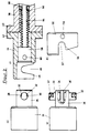
- FIGS. 2 and 3 The structure of the clutch 10 according to the invention results from FIGS. 2 and 3.
- the part of the clutch which is arranged on the shaft 22 of the pressure roller 12 is shown in FIGS. 2a and 2b.
- This consists of an adapter 24 which is in a pin 26th smaller diameter runs out.
- a transverse bore 28 is recessed, through which a bolt 30 is inserted, which projects on both sides beyond the transverse bore, as shown in FIG. 2b.
- the bolt 30 has inclined surfaces 32 on opposite sides, which are beveled in the axial direction of the pin 26, as can be seen, for example, from FIG. 2a.
- a through bore 34 is also provided in the bolt 30, through which a pin 36 engages, which is driven in from the end side of the pin 26, as shown in FIG. 2b.
- the bore 34 in the bolt 30 has a slightly larger diameter than the pin 36, so that the bolt 30 as a whole can be rotated slightly relative to the pin 26.
- FIGS. 2c and 2d The structure of the part of the clutch 10 which is formed on the drive shaft 33 results from FIGS. 2c and 2d.
- a flange 42 of a sleeve 44 is connected to an end flange 40 of the drive shaft 38.
- the end of the sleeve 44 has a fork piece 46 with a centering cutout 48.
- the centering cutout 48 runs perpendicular to the central axis of the sleeve 44 or the drive shaft 38.
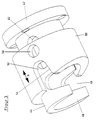
- a sliding ring 50 is slidably mounted on the sleeve 44, which is shown separately in FIG. 2d and in FIG. 3 in the pushed open position.
- the sliding ring also has a cutout 52 with a contact surface 54, the cutout 52 being oriented substantially perpendicular to the cutout 48.
- a through hole 56 is additionally arranged in the sliding ring 50.
- a piston 58 slidably runs in the sleeve 44, in which a through bore 60 is likewise excluded.
- a bolt (not shown here) runs through the through bore 60 and also through the through bores 56 of the sliding ring 50 and runs through an elongated hole 62 within the sleeve 44 (see FIG. 3).
- the sliding ring 50 is thus connected to the bolt 58 which is displaceably mounted within the sleeve. End positions for the piston 58 and for the sliding ring 50 are defined via the elongated hole 62 in connection with the bolt (not shown here).
- the sliding ring 50 can be moved together with the piston 58 in the double arrow direction b (see FIG. 3).
- the one end position which is brought about by contact of the bolt (not shown) on the left side of the elongated hole 62 in FIG. 3, is the closed position of the sliding ring and the coupling, in which the contact surface 54 bears against one of the inclined surfaces 32 of the bolt 30 as shown in FIG. 1.
- the opposite contact surface of the elongated hole 62 defines the open position of the sliding ring 50.
- a pull rod 64 is attached to the piston 58 running inside the sleeve 44, which first runs through the sleeve 44 and then through the hollow drive shaft 38 and, as shown in FIG. 1, is led out laterally.
- This pull rod 64 is connected with its laterally guided free end to a piston-cylinder unit, not shown here.
- a compression spring 66 runs parallel to the pull rod 64, which is supported on the one hand on one side of the piston 58 and on the other hand on stops 68 which are provided within the drive shaft 38.
- the compression spring 66 thus presses the piston 58 and thus the sliding ring 50 into the closed position, as shown in FIG. 1.
- the piston 58 and thus the sliding ring 50 can be moved against the force of the compression spring 66 in the direction of arrow a according to FIG. 1 via the piston-cylinder unit, not shown. This creates a simple automatic locking mechanism.
Landscapes
- Engineering & Computer Science (AREA)
- General Engineering & Computer Science (AREA)
- Mechanical Engineering (AREA)
- Rotary Presses (AREA)
- Replacement Of Web Rolls (AREA)
- Mechanical Operated Clutches (AREA)
Applications Claiming Priority (2)
| Application Number | Priority Date | Filing Date | Title |
|---|---|---|---|
| DE4441019A DE4441019C2 (de) | 1994-11-17 | 1994-11-17 | Wellenkupplung |
| DE4441019 | 1994-11-17 |
Publications (2)
| Publication Number | Publication Date |
|---|---|
| EP0713023A1 true EP0713023A1 (fr) | 1996-05-22 |
| EP0713023B1 EP0713023B1 (fr) | 1998-11-25 |
Family
ID=6533525
Family Applications (1)
| Application Number | Title | Priority Date | Filing Date |
|---|---|---|---|
| EP95114424A Expired - Lifetime EP0713023B1 (fr) | 1994-11-17 | 1995-09-14 | Accouplement d'arbres |
Country Status (7)
| Country | Link |
|---|---|
| US (1) | US5709499A (fr) |
| EP (1) | EP0713023B1 (fr) |
| JP (1) | JPH08210372A (fr) |
| KR (1) | KR100396401B1 (fr) |
| DE (2) | DE4441019C2 (fr) |
| ES (1) | ES2124482T3 (fr) |
| TW (1) | TW309579B (fr) |
Cited By (1)
| Publication number | Priority date | Publication date | Assignee | Title |
|---|---|---|---|---|
| EP1016520A1 (fr) * | 1998-12-01 | 2000-07-05 | Fischer & Krecke Gmbh & Co. | Accouplement d'entraínement pour cylindre d'impression |
Families Citing this family (7)
| Publication number | Priority date | Publication date | Assignee | Title |
|---|---|---|---|---|
| DE10227448A1 (de) * | 2002-06-20 | 2004-01-15 | Widia Gmbh | Vorrichtung zur lösbaren Verbindung einer Motorantriebswelle und einer Zylinderwelle einer Rotationsdruckmaschine |
| GB2417309A (en) * | 2004-08-17 | 2006-02-22 | Hsi-Tsai Chen | Releasable shaft coupling |
| US20060040750A1 (en) * | 2004-08-17 | 2006-02-23 | Hsi-Tsai Chen | Shaft coupling assembly |
| US7367881B2 (en) * | 2006-02-10 | 2008-05-06 | Agco Corporation | High capacity combine grain bin unload system |
| JP5194919B2 (ja) * | 2008-03-24 | 2013-05-08 | 富士ゼロックス株式会社 | 駆動力伝達装置および画像形成装置 |
| WO2011133946A2 (fr) * | 2010-04-22 | 2011-10-27 | Blue Belt Technologies, Llc | Mécanisme de fixation |
| CN106240144A (zh) * | 2016-08-24 | 2016-12-21 | 常州市群星印刷有限公司 | 连接杆固定的印刷机双轴承 |
Citations (5)
| Publication number | Priority date | Publication date | Assignee | Title |
|---|---|---|---|---|
| US3362050A (en) * | 1966-04-15 | 1968-01-09 | Norco Inc | Concentric tube releasable clasp |
| GB1194047A (en) * | 1967-08-29 | 1970-06-10 | John Joseph Mccarthy | Releasable Mechanical Coupling |
| US4057114A (en) * | 1976-01-07 | 1977-11-08 | Anderson Paul J | Hand-held ice auger |
| EP0334704A1 (fr) * | 1988-03-14 | 1989-09-27 | Ecia - Equipements Et Composants Pour L'industrie Automobile | Attache rapide du type à baionnette perfectionnée |
| EP0392323A1 (fr) | 1989-04-13 | 1990-10-17 | WindmÀ¶ller & Hölscher | Accouplement pour arbres décalés |
Family Cites Families (2)
| Publication number | Priority date | Publication date | Assignee | Title |
|---|---|---|---|---|
| US2901258A (en) * | 1957-09-30 | 1959-08-25 | Brandafi Gabriel | Drill press spindle |
| US4645373A (en) * | 1985-10-28 | 1987-02-24 | G. Miller Machine Co., Inc. | Quick release connectors |
-
1994
- 1994-11-17 DE DE4441019A patent/DE4441019C2/de not_active Expired - Fee Related
-
1995
- 1995-09-14 EP EP95114424A patent/EP0713023B1/fr not_active Expired - Lifetime
- 1995-09-14 ES ES95114424T patent/ES2124482T3/es not_active Expired - Lifetime
- 1995-09-14 DE DE59504330T patent/DE59504330D1/de not_active Expired - Lifetime
- 1995-10-18 TW TW084110943A patent/TW309579B/zh active
- 1995-10-24 US US08/547,238 patent/US5709499A/en not_active Expired - Fee Related
- 1995-11-13 KR KR1019950041074A patent/KR100396401B1/ko not_active Expired - Fee Related
- 1995-11-14 JP JP7295335A patent/JPH08210372A/ja active Pending
Patent Citations (5)
| Publication number | Priority date | Publication date | Assignee | Title |
|---|---|---|---|---|
| US3362050A (en) * | 1966-04-15 | 1968-01-09 | Norco Inc | Concentric tube releasable clasp |
| GB1194047A (en) * | 1967-08-29 | 1970-06-10 | John Joseph Mccarthy | Releasable Mechanical Coupling |
| US4057114A (en) * | 1976-01-07 | 1977-11-08 | Anderson Paul J | Hand-held ice auger |
| EP0334704A1 (fr) * | 1988-03-14 | 1989-09-27 | Ecia - Equipements Et Composants Pour L'industrie Automobile | Attache rapide du type à baionnette perfectionnée |
| EP0392323A1 (fr) | 1989-04-13 | 1990-10-17 | WindmÀ¶ller & Hölscher | Accouplement pour arbres décalés |
Cited By (2)
| Publication number | Priority date | Publication date | Assignee | Title |
|---|---|---|---|---|
| US6244406B1 (en) | 1998-01-12 | 2001-06-12 | Fischer & Krecke Gmbh & Co. | Drive clutch for a pressure cylinder |
| EP1016520A1 (fr) * | 1998-12-01 | 2000-07-05 | Fischer & Krecke Gmbh & Co. | Accouplement d'entraínement pour cylindre d'impression |
Also Published As
| Publication number | Publication date |
|---|---|
| TW309579B (fr) | 1997-07-01 |
| DE4441019A1 (de) | 1996-06-05 |
| KR960018284A (ko) | 1996-06-17 |
| DE59504330D1 (de) | 1999-01-07 |
| US5709499A (en) | 1998-01-20 |
| KR100396401B1 (ko) | 2003-11-28 |
| EP0713023B1 (fr) | 1998-11-25 |
| DE4441019C2 (de) | 1997-06-05 |
| JPH08210372A (ja) | 1996-08-20 |
| ES2124482T3 (es) | 1999-02-01 |
Similar Documents
| Publication | Publication Date | Title |
|---|---|---|
| DE112013003482B4 (de) | Spannvorrichtung | |
| DE3837007C2 (fr) | ||
| DE19537421C1 (de) | Verfahren und Vorrichtung zum Ankuppeln eines Zylinders | |
| DE2436529B1 (de) | Kraftbetätigtes Spannfutter | |
| DE2853901C2 (de) | Eindruckvorrichtung für eine Druckmaschine, insbesondere Rotationsdruckmaschine | |
| DE4447124C1 (de) | Zylinder einer Rotationsdruckmaschine | |
| EP0713023B1 (fr) | Accouplement d'arbres | |
| DE2211453C3 (de) | Führung für den Sattel einer Schwimmsattel-Scheibenbremse am Bremsträger | |
| DE4415340C2 (de) | Druckwerkszylinder einer Rollenrotationsdruckmaschine | |
| DE2734382C2 (de) | Zentriervorrichtung für einen Wellenzapfen in einer Gelenkwelle | |
| DE4204604C2 (de) | Vorrichtung zum Antrieb von Reibwalzen in Farbwerken | |
| WO2000048776A1 (fr) | Dispositif permettant d'assembler de façon amovible un outil avec une broche de machine | |
| EP1745929B1 (fr) | Machine d'impression | |
| DE10242009B4 (de) | Druckmaschine, vorzugsweise Flexodruckmaschine | |
| EP0676278A1 (fr) | Dispositif de réglage de la course pour presses ou poinçonneuses | |
| EP1016520B1 (fr) | Accouplement d'entraínement pour cylindre d'impression | |
| DE10122260B4 (de) | Linearantriebseinrichtung zum Öffnen und Schließen von Formwerkzeugen sowie Aufbringen einer Schließkraft hierauf | |
| EP1984181B1 (fr) | Couplage de cylindre gravé | |
| EP0545004A2 (fr) | Entraînement pour rotatives | |
| DE4113491A1 (de) | Verreibwalze fuer druckmaschinen | |
| DE3801749A1 (de) | Walzwerksantrieb mit zwischen kammwalzen und arbeitswalzen loesbar angeordneten gelenkspindeln | |
| DE19803557C2 (de) | Antrieb für ein rotierendes Bauteil einer Druckmaschine | |
| DE3209658C2 (de) | Kreuzgelenk | |
| DE19714595B4 (de) | Vorrichtung an einem Zweistufenauswerfer einer Kunststoff-Verformungsmaschine | |
| DE2852420B1 (de) | Futterwuerfelpresse |
Legal Events
| Date | Code | Title | Description |
|---|---|---|---|
| PUAI | Public reference made under article 153(3) epc to a published international application that has entered the european phase |
Free format text: ORIGINAL CODE: 0009012 |
|
| AK | Designated contracting states |
Kind code of ref document: A1 Designated state(s): CH DE ES FR GB IT LI |
|
| 17P | Request for examination filed |
Effective date: 19961122 |
|
| 17Q | First examination report despatched |
Effective date: 19970128 |
|
| GRAG | Despatch of communication of intention to grant |
Free format text: ORIGINAL CODE: EPIDOS AGRA |
|
| GRAG | Despatch of communication of intention to grant |
Free format text: ORIGINAL CODE: EPIDOS AGRA |
|
| GRAH | Despatch of communication of intention to grant a patent |
Free format text: ORIGINAL CODE: EPIDOS IGRA |
|
| GRAH | Despatch of communication of intention to grant a patent |
Free format text: ORIGINAL CODE: EPIDOS IGRA |
|
| GRAA | (expected) grant |
Free format text: ORIGINAL CODE: 0009210 |
|
| AK | Designated contracting states |
Kind code of ref document: B1 Designated state(s): CH DE ES FR GB IT LI |
|
| REG | Reference to a national code |
Ref country code: CH Ref legal event code: NV Representative=s name: BOVARD AG PATENTANWAELTE Ref country code: CH Ref legal event code: EP |
|
| REF | Corresponds to: |
Ref document number: 59504330 Country of ref document: DE Date of ref document: 19990107 |
|
| GBT | Gb: translation of ep patent filed (gb section 77(6)(a)/1977) |
Effective date: 19981231 |
|
| ITF | It: translation for a ep patent filed | ||
| REG | Reference to a national code |
Ref country code: ES Ref legal event code: FG2A Ref document number: 2124482 Country of ref document: ES Kind code of ref document: T3 |
|
| ET | Fr: translation filed | ||
| PLBE | No opposition filed within time limit |
Free format text: ORIGINAL CODE: 0009261 |
|
| STAA | Information on the status of an ep patent application or granted ep patent |
Free format text: STATUS: NO OPPOSITION FILED WITHIN TIME LIMIT |
|
| 26N | No opposition filed | ||
| REG | Reference to a national code |
Ref country code: GB Ref legal event code: IF02 |
|
| PGFP | Annual fee paid to national office [announced via postgrant information from national office to epo] |
Ref country code: GB Payment date: 20040825 Year of fee payment: 10 |
|
| PGFP | Annual fee paid to national office [announced via postgrant information from national office to epo] |
Ref country code: FR Payment date: 20040827 Year of fee payment: 10 |
|
| PGFP | Annual fee paid to national office [announced via postgrant information from national office to epo] |
Ref country code: CH Payment date: 20040903 Year of fee payment: 10 |
|
| PGFP | Annual fee paid to national office [announced via postgrant information from national office to epo] |
Ref country code: ES Payment date: 20040917 Year of fee payment: 10 |
|
| PG25 | Lapsed in a contracting state [announced via postgrant information from national office to epo] |
Ref country code: IT Free format text: LAPSE BECAUSE OF NON-PAYMENT OF DUE FEES Effective date: 20050914 Ref country code: GB Free format text: LAPSE BECAUSE OF NON-PAYMENT OF DUE FEES Effective date: 20050914 |
|
| PG25 | Lapsed in a contracting state [announced via postgrant information from national office to epo] |
Ref country code: ES Free format text: LAPSE BECAUSE OF NON-PAYMENT OF DUE FEES Effective date: 20050915 |
|
| PG25 | Lapsed in a contracting state [announced via postgrant information from national office to epo] |
Ref country code: LI Free format text: LAPSE BECAUSE OF NON-PAYMENT OF DUE FEES Effective date: 20050930 Ref country code: CH Free format text: LAPSE BECAUSE OF NON-PAYMENT OF DUE FEES Effective date: 20050930 |
|
| REG | Reference to a national code |
Ref country code: CH Ref legal event code: PL |
|
| GBPC | Gb: european patent ceased through non-payment of renewal fee |
Effective date: 20050914 |
|
| PG25 | Lapsed in a contracting state [announced via postgrant information from national office to epo] |
Ref country code: FR Free format text: LAPSE BECAUSE OF NON-PAYMENT OF DUE FEES Effective date: 20060531 |
|
| REG | Reference to a national code |
Ref country code: FR Ref legal event code: ST Effective date: 20060531 |
|
| REG | Reference to a national code |
Ref country code: ES Ref legal event code: FD2A Effective date: 20050915 |
|
| PGFP | Annual fee paid to national office [announced via postgrant information from national office to epo] |
Ref country code: DE Payment date: 20120930 Year of fee payment: 18 |
|
| PG25 | Lapsed in a contracting state [announced via postgrant information from national office to epo] |
Ref country code: DE Free format text: LAPSE BECAUSE OF NON-PAYMENT OF DUE FEES Effective date: 20130403 |
|
| REG | Reference to a national code |
Ref country code: DE Ref legal event code: R119 Ref document number: 59504330 Country of ref document: DE Effective date: 20130403 |