EP0713029A1 - Proportionalventil - Google Patents
Proportionalventil Download PDFInfo
- Publication number
- EP0713029A1 EP0713029A1 EP95108282A EP95108282A EP0713029A1 EP 0713029 A1 EP0713029 A1 EP 0713029A1 EP 95108282 A EP95108282 A EP 95108282A EP 95108282 A EP95108282 A EP 95108282A EP 0713029 A1 EP0713029 A1 EP 0713029A1
- Authority
- EP
- European Patent Office
- Prior art keywords
- pressure
- damping
- piston
- valve
- vibration damper
- Prior art date
- Legal status (The legal status is an assumption and is not a legal conclusion. Google has not performed a legal analysis and makes no representation as to the accuracy of the status listed.)
- Granted
Links
Images

Classifications
-
- F—MECHANICAL ENGINEERING; LIGHTING; HEATING; WEAPONS; BLASTING
- F16—ENGINEERING ELEMENTS AND UNITS; GENERAL MEASURES FOR PRODUCING AND MAINTAINING EFFECTIVE FUNCTIONING OF MACHINES OR INSTALLATIONS; THERMAL INSULATION IN GENERAL
- F16F—SPRINGS; SHOCK-ABSORBERS; MEANS FOR DAMPING VIBRATION
- F16F9/00—Springs, vibration-dampers, shock-absorbers, or similarly-constructed movement-dampers using a fluid or the equivalent as damping medium
- F16F9/32—Details
- F16F9/44—Means on or in the damper for manual or non-automatic adjustment; such means combined with temperature correction
- F16F9/46—Means on or in the damper for manual or non-automatic adjustment; such means combined with temperature correction allowing control from a distance, i.e. location of means for control input being remote from site of valves, e.g. on damper external wall
- F16F9/464—Control of valve bias or pre-stress, e.g. electromagnetically
-
- F—MECHANICAL ENGINEERING; LIGHTING; HEATING; WEAPONS; BLASTING
- F16—ENGINEERING ELEMENTS AND UNITS; GENERAL MEASURES FOR PRODUCING AND MAINTAINING EFFECTIVE FUNCTIONING OF MACHINES OR INSTALLATIONS; THERMAL INSULATION IN GENERAL
- F16F—SPRINGS; SHOCK-ABSORBERS; MEANS FOR DAMPING VIBRATION
- F16F9/00—Springs, vibration-dampers, shock-absorbers, or similarly-constructed movement-dampers using a fluid or the equivalent as damping medium
- F16F9/32—Details
- F16F9/34—Special valve constructions; Shape or construction of throttling passages
- F16F9/348—Throttling passages in the form of annular discs or other plate-like elements which may or may not have a spring action, operating in opposite directions or singly, e.g. annular discs positioned on top of the valve or piston body
- F16F9/3485—Throttling passages in the form of annular discs or other plate-like elements which may or may not have a spring action, operating in opposite directions or singly, e.g. annular discs positioned on top of the valve or piston body characterised by features of supporting elements intended to guide or limit the movement of the annular discs
-
- F—MECHANICAL ENGINEERING; LIGHTING; HEATING; WEAPONS; BLASTING
- F16—ENGINEERING ELEMENTS AND UNITS; GENERAL MEASURES FOR PRODUCING AND MAINTAINING EFFECTIVE FUNCTIONING OF MACHINES OR INSTALLATIONS; THERMAL INSULATION IN GENERAL
- F16F—SPRINGS; SHOCK-ABSORBERS; MEANS FOR DAMPING VIBRATION
- F16F9/00—Springs, vibration-dampers, shock-absorbers, or similarly-constructed movement-dampers using a fluid or the equivalent as damping medium
- F16F9/32—Details
- F16F9/44—Means on or in the damper for manual or non-automatic adjustment; such means combined with temperature correction
- F16F9/46—Means on or in the damper for manual or non-automatic adjustment; such means combined with temperature correction allowing control from a distance, i.e. location of means for control input being remote from site of valves, e.g. on damper external wall
- F16F9/465—Means on or in the damper for manual or non-automatic adjustment; such means combined with temperature correction allowing control from a distance, i.e. location of means for control input being remote from site of valves, e.g. on damper external wall using servo control, the servo pressure being created by the flow of damping fluid, e.g. controlling pressure in a chamber downstream of a pilot passage
Definitions
- the invention relates to a proportional valve for a hydraulic vibration damper with a piston axially displaceably guided in a damping cylinder and connected to a piston rod, the piston having pressure-dependent damping valves for an exchange of damping fluid in the tension and compression stages and dividing the damping cylinder into two working spaces , and in which there are passages through which the pressure medium acting on the damping valves flows, and wherein the piston has an electromagnetically actuated control slide arranged in a bypass duct system and throttling the medium flow rate present there, the side of the damping valve facing away from the passageways one over the Bypass channel system having the pressure chamber connected to the opposite working space, and in which the pressure space is resiliently sealed from the associated working space.
- Such proportional valves work with a pilot control in such a way that the damping valve can be controlled by the main flow due to the pressure acting on the side of the damping valve facing away from the passage channels in the pressure chamber arranged there.
- a back pressure is built up in the pressure chamber with the help of a bypass duct system, which - apart from the constant flow rates that may be present in the damping valve disc or in the associated support edge - only releases the main flow occurring at a predetermined operating state.
- Such a proportional valve is disclosed in DE 33 48 176 C2, in which the damping valve disks can be acted upon via a support body 38 by a control pressure present in an admission chamber 40.
- This control pressure is applied via a bypass channel system, which can be closed or opened or throttled in its medium flow rate with the aid of an additional disk valve 45.
- Disadvantages of the configuration shown here are, on the one hand, the only one-sided configuration of a pilot control with an electromagnetically controllable valve that is effective for only one side, and the configuration of the pressurization chamber completely within the piston body with only one side that can be closed by a further support element.
- discontinuities in the volume flow e.g. favored by fluttering of the valve, especially in the case of high-frequency and low-amplitude vibrations.
- the invention was therefore based on the object of providing a proportional valve with a pilot control, which is not only effective and controllable on both sides, but which is particularly useful in production and in the Manufacturing is easy to handle due to the simplest possible construction and can avoid any discontinuities in the bypass flow by precisely defining the flow cross-sections.
- the pressure chamber is limited by the damping valve disc by an elastic element serving for resilient sealing with respect to the associated working chamber and by the wall parts of the piston body and / or piston insert rings containing the orifices of the bypass channel system, the elastic element of the pressure chamber belonging to the respective opposite working chamber is opened by a medium pressure occurring in the opposite work space.
- Such a design of the pressure chamber and the damping valve disks in combination with the elastic elements for resilient sealing not only achieves a very simple piston structure, which essentially consists of annular, easily assembled parts, but also reduces the number of channels in the bypass system characterized in that not a single channel, but rather the resilient seal with respect to the work space associated with an opposing damping valve disk, is used for the entry of the volume portion required for the control into the bypass channel system.
- a particularly advantageous embodiment is designed such that the elastic elements resiliently sealing the pressure chamber from the associated work chamber at a damping valve disks which block the pressure level to open the opposite and the other work chamber, one in the opposite pressure chamber on the side facing away from the passage channels release the control flow of the medium acting on the damping valve disks that block the other working space.
- control of the opposite damping valve disc is achieved in a simple manner and depending on the throttling effects set in the bypass duct system, with any piston movement having a sufficient control pressure at the beginning, which is retained even if the direction of movement is reversed and the control slide is closed.
- the elastic elements are designed as cup-shaped spring rings mounted in the piston body and the damping valve disk, in general their outer edge here.
- cup-shaped rings are very easy to manufacture and their suspension properties can be set as desired.
- Equally easy to manufacture and adjust is a design of the elastic elements as cranked plate springs mounted in the piston body and loading the damping valve disk.
- Elastic elements which are designed as elastic sealing rings mounted in the piston body and stressing the damping valve disk, are advantageously suitable for the formation of proportional valves which are constructed in a particularly space-saving manner in the axial direction.
- Such elements designed as elastic sealing rings can also be produced in conjunction with prefabricated, annular receiving bodies, so that the assembly is further facilitated.
- the elastic elements are mounted in the piston body and the Damping valve disc metal-non-metal composite materials are formed.
- Such composite materials consist essentially of a combination of elastomers or rubber and metal.
- outlet openings of the bypass channel system which open into the respective work spaces are at an entry of the pressure medium from the
- check valves are, on the one hand, very simple to operate and assemble and form mechanically safe sealing elements that are tolerant of high-frequency vibrations.
- the electromagnetically operable control slide which throttles the medium flow in the bypass channel system is designed as a separate control element which is effective in the flow direction upstream of the check valves, both in the rebound and in the compression stage.
- the throttle function is kept completely separate from the sealing function of the check valves, and there is a discontinuous flow volume flow in a precisely defined channel cross section.
- this allows control for both directions of movement, ie for the rebound and compression stages, with only one electromagnetically actuated control slide. In a further step, this in turn reduces the size of the piston and simplifies the overall construction.
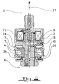
- the piston slides into a cylinder, not shown here, and separates the two working spaces 5 and 6.
- the piston has passage channels 7 and 8 in its base body, which direct the main flow of the damping medium to the damping valve disks 9 and 10, which together with the cup-shaped elastic elements 11 and 12 form the pressure-dependent damping valves 13 and 14.
- the medium pressure in the working space 6 first lifts the inwardly curved pot collar 16 of the elastic element 12 and flows through the bore 17 and through the channel 3 and the bore 18 at the control valve throttling the control flow 19 into the pressure chamber 20 and there builds up a counter pressure to the main flow of the damping medium, which flows through the channel 8 and acts on the damping valve disk 9.
- a further opening of the control slide 19 causes a pressure reduction in the pressure chamber 20, since the control current can then flow through the channel 3 via the control chamber 22, the channel 2 and via the check valve 23 into the opposite working chamber 5.
- the control slide is controlled by the electromagnets 24, with a spring 25 ensuring that the control slide 19 is in a normal position and is blocked.
- FIG. 2 shows an embodiment with an elastic spring element designed as a cranked plate spring 26 on the lower side.
- control volume portion initially flows by opening the inwardly curved cup collar of the pot-shaped upper elastic element 28 and throttled by the control slide 19 through the channels and bores 18, 3, 22 and 4 of the channel system before the pressure chamber 29 reached where with
Landscapes
- Engineering & Computer Science (AREA)
- General Engineering & Computer Science (AREA)
- Mechanical Engineering (AREA)
- Physics & Mathematics (AREA)
- Electromagnetism (AREA)
- Magnetically Actuated Valves (AREA)
- Fluid-Damping Devices (AREA)
- Fluid-Driven Valves (AREA)
- Safety Valves (AREA)
- Control Of Fluid Pressure (AREA)
Abstract
Description
- Die Erfindung betrifft ein Proportionalventil für einen hydraulischen Schwingungsdämpfer mit einem in einem Dämpfungszylinder axial verschieblich geführten und mit einer Kolbenstange verbundenen Kolben, wobei der Kolben druckabhängige Dämpfungsventile für einen Austausch von Dämpfungsflüssigkeit in der Zug- und in der Druckstufe aufweist und den Dämpfungszylinder in zwei Arbeitsräume unterteilt, und bei dem Durchtrittskanäle vorhanden sind, durch welche das die Dämpfungsventile beaufschlagende Druckmedium strömt, und wobei der Kolben einen in einem Bypass-Kanalsystem angeordneten und den dort vorhandenen Mediumsdurchfluß drosselnden elektromagnetisch betätigbaren Steuerschieber aufweist, wobei die den Durchtrittskanälen abgewandte Seite des Dämpfungsventiles einen über das Bypass-Kanalsystem mit dem jeweils gegenüberliegenden Arbeitsraum verbundenen Druckraum aufweist, und bei dem der Druckraum federnd gegenüber dem zugehörigen Arbeitsraum abgedichtet ist.
- Solche Proportionalventile arbeiten mit einer Vorsteuerung in der Art, daß durch den auf die den Durchtrittskanälen abgewandte Seite des Dämpfungsventiles wirkenden Druck im dort angeordneten Druckraum ein Abheben des Dämpfungsventiles durch den Hauptstrom steuerbar wird. Hierzu wird mit Hilfe eines Bypass-Kanalsystems ein Gegendruck in dem Druckraum aufgebaut, welcher - abgesehen von den durch die eventuell in der Dämpfungsventilscheibe oder im zugehörigen Auflagerand vorhandenen Konstantdurchflüssen - erst zu einem vorbestimmten Betriebszustand den auftretenden Hauptstrom freigibt.
- Ein solches Proportionalventil ist in der DE 33 48 176 C2 offenbart, bei der die Dämpfungsventilscheiben über einen Stützkörper 38 durch einen in einer Beaufschlagungskammer 40 vorhandenen Steuerdruck beaufschlagbar sind. Dieser Steuerdruck wird über ein Bypass-Kanalsystem aufgebracht, welches mit Hilfe eines zusätzlichen Scheibenventiles 45 verschlossen oder geöffnet bzw. in seinem Mediumsdurchfluß gedrosselt werden kann.
- Nachteilig bei der hier gezeigten Ausbildung ist zum einen die lediglich einseitige Ausbildung einer Vorsteuerung mit einem nur für eine Seite wirksamen elektromagnetisch steuerbaren Ventil, als auch die Ausbildung der Druckbeaufschlagungskammer vollständig innerhalb des Kolbenkörpers mit lediglich einer durch ein weiteres Stützelement verschließbaren Seite.
- Dieser Aufbau ist bereits für die dargestellte einseitige Ausbildung kompliziert und fertigungstechnisch nur schwer zu handhaben, was den Gedanken einer eventuell doppelseitigen Ausbildung mit entgegengesetzt wirkenden Beaufschlagungskammern nicht sinnvoll erscheinen läßt.
- Zudem sind eine Reihe von zusätzlichen, im Kolbenkörper verlaufenden Bypassbohrungen notwendig und auch eine Ausnehmung bzw. Bohrung innerhalb der Dämpfungsventilscheibe, welche für einen ungehinderten Durchtritt des zur Steuerung nötigen Volumenanteiles erforderlich wird.
- Ein weiterer Nachteil ergibt sich in der Zusammenfassung der Funktionen des Absperrventiles und des Steuerventiles durch die genannte Ventilscheibe 45. Hierdurch wird das Entstehen von Unstetigkeiten im Volumenstrom, z.B. durch Flattern des Ventiles, insbesondere bei hochfrequenten und in der Amplitude niedrigen Schwingungen begünstigt.
- Der Erfindung lag also die Aufgabe zugrunde, ein Proportionalventil mit einer Vorsteuerung bereitzustellen, welches nicht nur doppelseitig wirksam und steuerbar ist, sondern welches insbesondere in der Fertigung und in der Herstellung durch eine möglichst einfache Bauweise leicht zu handhaben ist und jegliche Unstetigkeiten in der Bypass-Strömung durch exakte Definition der Strömungsquerschnitte vermeiden kann.
- Gelöst wird diese Aufgabe durch die Merkmale des Hauptanspruchs. Vorteilhafte Ausbildungen sind in den Unteransprüchen erfaßt.
- Hierbei wird der Druckraum durch die Dämpfungsventilscheibe durch ein zur federnden Abdichtung gegenüber dem zugehörigen Arbeitsraum dienendes elastisches Element und durch die die Mündungsöffnungen des Bypass-Kanalsystems enthaltenden Wandungsteilen des Kolbenkörpers und / oder von Kolbeneinsatzringen begrenzt, wobei das elastische Element des zum jeweils gegenüberliegenden Arbeitsraum gehörigen Druckraumes durch einen im gegenüberliegenden Arbeitsraum auftretenden Mediumsdruck geöffnet wird.
- Durch eine solche Ausbildung des Druckraumes und der Dämpfungsventilscheiben in Kombination mit den elastischen Elementen zur federnden Abdichtung erreicht man nicht nur einen sehr einfachen Kolbenaufbau, der im wesentlichen aus ringförmigen, leicht zusammensetzbaren Teilen besteht, sondern man reduziert auch die Anzahl der Kanäle im Bypass-System dadurch, daß für den Eintritt des für die Steuerung nötigen Volumenanteiles in das Bypass-Kanalsystem nicht etwa ein einzelner Kanal, sondern die federnde Abdichtung gegenüber dem jeweils einer gegenüberliegenden Dämpfungsventilscheibe zugehörigen Arbeitsraum genutzt wird.
- Hierzu ist eine besonders vorteilhafte Ausbildung so ausgeführt, daß die den Druckraum federnd gegenüber dem zugehörigen Arbeitsraum abdichtenden elastischen Elemente bei einem unterhalb des Druckniveaus zur Öffnung der gegenüberliegenden und den jeweils anderen Arbeitsraum sperrenden Dämpfungsventilscheiben einen in dem gegenüberliegenden Druckraum auf die den Durchtrittskanälen abgewandte Seite der den jeweils anderen Arbeitsraum sperrenden Dämpfungsventilscheiben wirkenden Steuerstrom des Mediums freigeben.
- Hierdurch wird auf einfache Weise und abhängig von dem im Bypass-Kanalsystem eingestellten Drosselungseffekten eine Ansteuerung der jeweils gegenüberliegenden Dämpfungsventilscheibe erreicht, wobei bereits zu Beginn jegliche Kolbenbewegung ein ausreichender Steuerdruck zur Verfügung steht, der auch bei eventueller Umkehr der Bewegungsrichtung und geschlossenem Steuerschieber erhalten bleibt.
- Hierzu ist es vorteilhaft, daß die elastischen Elemente als topfförmige, im Kolbenkörper gelagerte und die Dämpfungsventilscheibe, hier im allgemeinen deren äußeren Rand belastende Federringe ausgebildet sind.
- Solche topfförmigen Ringe lassen sich sehr leicht herstellen und in ihren Federungseigenschaften beliebig einstellen.
- Gleichermaßen einfach herstellbar und einstellbar ist eine Ausbildung der elastischen Elemente als gekröpfte, im Kolbenkörper gelagerte und die Dämpfungsventilscheibe belastende Tellerfedern.
- Für Ausbildungen von Proportionalventilen, die in axialer Richtung besonders platzsparend konstruiert sind, eigenen sich vorteilhafterweise elastische Elemente, welche als im Kolbenkörper gelagerte und die Dämpfungsventilscheibe belastende elastische Dichtungsringe ausgebildet sind.
- Solche als elastische Dichtungsringe ausgebildete Elemente lassen sich auch in Verbindung mit vorgefertigten, ringförmigen Aufnahmekörpern herstellen, so daß die Montage weiterhin erleichtert wird.
- Eine weitere vorteilhafte Ausbildung erreicht man dadurch, daß die elastischen Elemente als im Kolbenkörper gelagerte und die Dämpfungsventilscheibe belastende Metall-Nichtmetall-Verbundwerkstoffe ausgebildet sind. Solche Verbundwerkstoffe bestehen im wesentlichen aus einer Verbindung von Elastomeren oder Gummi und Metall.
- Hierdurch ergibt sich in dem Zusammenwirken von Elementen unterschiedlicher Elastizität eine besonders weich einstellbare Dämpfungskennlinie.
- In einer weiteren vorteilhaften Ausbildung sind die in die jeweiligen Arbeitsräume mündenden Austrittsöffnungen des Bypass-Kanalsystems mit einem einen Eintritt des Druckmediums aus dem
- jeweiligen Arbeitsraum in das Bypass-Kanalsystem verhinderndem Rückschlagventil versehen.
- Solche separaten Rückschlagventile sind zum einen in ihrer Funktionsweise und in ihrer Montage sehr einfach und bilden mechanisch sichere und gegenüber hochfrequenten Schwingungen tolerante Dichtungselemente.
- In einer weiteren vorteilhaften Ausbildung ist der den im Bypass-Kanalsystem vorhandenen Mediumsdurchfluß drosselnde elektromagnetisch betätigbare Steuerschieber als separates und in Fließrichtung vor den Rückschlagventilen sowohl in der Zug- als auch in der Druckstufe wirksames Steuerelement ausgebildet.
- Durch eine solche Konstruktion wird die Drosselfunktion völlig getrennt gehalten von der Dichtfunktion der Rückschlagventile, und es ergibt sich ein von Unstetigkeiten freier Drosselvolumenstrom in einem genau definierten Kanalquerschnitt. Zudem kann hierdurch mit lediglich einem elektromagnetisch betätigbaren Steuerschieber eine Steuerung für beide Bewegungsrichtungen, d.h. für die Zug- und die Druckstufe, vorgenommen werden. Dies wiederum verringert in einem weiteren Schritt die Baugröße des Kolbens und vereinfacht die Gesamtkonstruktion.
- Anhand einiger Ausführungsbeispiele soll die Erfindung näher verdeutlicht werden. Es zeigen
- Fig. 1
- ein erfindungsgemäß ausgebildetes Proportionalventil mit einem als topfförmiger Federring ausgebildeten elastischen Elemenet
- Fig. 2
- ein erfindungsgemäßes Proportionalventil mit einem als gekröpfte Tellerfeder ausgebildeten elastischen Element.
- In der Fig. 1 erkennt man den Kolben 1 mit seinem u.a. aus den Kanälen 2, 3 und 4 bestehenden Bypass-Kanalsystem.
- Der Kolben gleitet in einen hier nicht näher dargestellten Zylinder und trennt die beiden Arbeitsräume 5 und 6.
- Der Kolben weist in seinem Grundkörper Durchtrittskanäle 7 und 8 auf, welche den Hauptstrom des Dämpfungsmediums auf die Dämpfungsventilscheiben 9 und 10 leiten, welche zusammen mit den topfförmig ausgebildeten elastischen Elementen 11 und 12 die druckabhängigen Dämpfungsventile 13 und 14 bilden.
- In der Druckstufenbewegungsrichtung 15 des Kolbens, welche hier exemplarisch dargestellt ist, hebt der Mediumsdruck im Arbeitsraum 6 zunächst den nach innen gebogenen Topfkragen 16 des elastischen Elementes 12 und strömt durch die Bohrung 17 sowie durch den Kanal 3 und die Bohrung 18 bei den Steuerstrom drosselndem Steuerschieber 19 in den Druckraum 20 und baut dort einen Gegendruck zu dem Hauptstrom des Dämpfungsmediums auf, welcher durch den Kanal 8 strömt und auf die Dämpfungsventilscheibe 9 wirkt.
- Ein weiteres Öffnen des Steuerschiebers 19 bewirkt einen Druckabbau im Druckraum 20, da dann der Steuerstrom durch den Kanal 3 über den Steuerraum 22, den Kanal 2 und über das Rückschlagventil 23 in den gegenüberliegenden Arbeitsraum 5 abströmen kann.
- Angesteuert wird der Steuerschieber durch die Elektromagneten 24, wobei eine Feder 25 für eine Grundstellung und Sperrung des Steuerschiebers 19 sorgt.
- Die Fig. 2 zeigt eine Ausführung mit einem als gekröpfte Tellerfeder 26 ausgebildeten elastischen Federelement auf der unteren Seite.
- In der hier dargestellten Bewegungsrichtung 27, d.h. in der Zugstufe des Kolbens, strömt der Steuervolumen-Anteil zunächst unter Öffnen des einwärts gebogenen Topfkragens des topfförmigen oberen elastischen Elementes 28 und gedrosselt durch den Steuerschieber 19 durch die Kanäle und Bohrungen 18, 3, 22 und 4 des Kanalsystems, bevor es den Druckraum 29 erreicht, wo mit
- Hilfe des als gekröpfte Tellerfeder 26 ausgebildeten unteren elastischen Elementes ein Gegendruck zu dem durch den Kanal 7 geleiteten Hauptstrom des Dämpfungsmediums auf die Dämpfungsventilscheibe 10 ausgeübt wird.
-
- 1
- Kolben
- 2,3,4
- Kanal
- 5, 6
- Arbeitsraum
- 7, 8
- Durchtrittskanal
- 9, 10
- Dämpfungsventilscheibe
- 11, 12
- elastisches Element
- 13, 14
- druckabhängiges Dämpfungsventil
- 15
- Bewegungsrichtung i.d. Druckstufe
- 16
- Topfkragen / topfförmiger Federring
- 17, 18
- Bohrung
- 19
- Steuerschieber
- 20, 21
- Druckranm
- 22
- Steuerraum
- 23
- Rückschlagventil
- 24
- Elektromagnet
- 25
- Feder
- 26
- gekröpfte Tellerfeder
- 27
- Bewegungsrichtung i.d. Zugstufe
- 28
- Topfkragen / topfförmiger Federring
- 29
- Druckraum
Claims (8)
- Proportionalventil für einen hydraulischen Schwingungsdämpfer mit einem in einem Dämpfungszylinder axial verschieblich geführten und mit einer Kolbenstange verbundenen Kolben, wobei der Kolben druckabhängige Dämpfungsventile für einen Austausch von Dämpfungsflüssigkeit in der Zug- und in der Druckstufe aufweist und den Dämpfungszylinder in zwei Arbeitsräume unterteilt, und bei dem Durchtrittskanäle vorhanden sind, durch welche das die Dämpfungsventile beaufschlagende Druckmedium strömt, und wobei der Kolben einen in einem Bypass-Kanalsystem angeordneten und den dort vorhandenen Mediumsdurchfluß drosselnden elektromagnetisch betätigbaren Steuerschieber aufweist, wobei die den Durchtrittskanälen abgewandte Seite des Dämpfungsventiles einen über das Bypass-Kanalsystem mit dem jeweils gegenüberliegenden Arbeitsraum verbundenen Druckraum aufweist, und bei dem der Druckraum federnd gegenüber dem zugehörigen Arbeitsraum abgedichtet ist,
dadurch gekennzeichnet, daß der
Druckraum durch die Dämpfungsventilscheibe, durch ein zur federnden Abdichtung gegenüber dem zugehörigen Arbeitsraum dienendes elastisches Element und durch die die Mündungsöffnungen des Bypass-Kanalsystems enthaltenden Wandungsteile des Kolbenkörpers und /oder von Kolbeneinsatzringen begrenzt wird, wobei das elastische Element des zum jeweils gegenüberliegenden Arbeitsraum gehörigen Druckraumes durch einen im gegenüberliegenden Arbeitsraum auftretenden Mediumsdruck geöffnet wird. - Proportionalventil für einen hydraulischen Schwingungsdämpfer nach Anspruch 1,
dadurch gekennzeichnet,
daß die den Druckraum federnd gegenüber dem zugehörigen Arbeitsraum abdichtenden elastischen Elemente bei einem unterhalb des Druckniveaus zur Öffnung der gegenüberliegenden und den jeweils anderen Arbeitsraum sperrenden Dämfungsventilscheiben einen in dem gegenüberliegenden Druckraum auf die den Durchtrittskanälen abgewandte Seite der den jeweils anderen Arbeitsraum sperrenden Dämfungsventilscheiben wirkenden Steurstrom des Mediums freigeben. - Proportionalventil für einen hydraulischen Schwingungsdämpfer nach einem der vorhergehenden Ansprüche,
dadurch gekennzeichnet,
daß die elastischen Elemente als topfförmige, im Kolbenkörper gelagerte und die Dämpfungsventilscheibe belastende Federringe ausgebildet sind. - Proportionalventil für einen hydraulischen Schwingungsdämpfer nach einem der vorhergehenden Ansprüche,
dadurch gekennzeichnet,
daß die elastischen Elemente als gekröpfte, im Kolbenkörper gelagerte und die Dämpfungsventilscheibe belastende Tellerfedern ausgebildet sind. - Proportionalventil für einen hydraulischen Schwingungsdämpfer nach einem der vorhergehenden Ansprüche,
dadurch gekennzeichnet,
daß die elastischen Elemente als im Kolbenkörper gelagerte und die Dämpfungsventilscheibe belastende elastische Dichtungsringe ausgebildet sind. - Proportionalventil für einen hydraulischen Schwingungsdämpfer nach einem der vorhergehenden Ansprüche,
dadurch gekennzeichnet,
daß die elastischen Elemente als im Kolbenkörper gelagerte und die Dämpfungsventilscheibe belastende Metall-Nichtmetall-Verbundwerkstoffe ausgebildet sind. - Proportionalventil für einen hydraulischen Schwingungsdämpfer nach einem der vorhergehenden Ansprüche,
dadurch gekennzeichnet,
daß die in die jeweiligen Arbeitsräume mündenden Austrittsöffnungen des Bypass-Kanalsystems mit einem einen Eintritt des Druckmediums aus dem jeweiligen Arbeitsraum in das Bypass-Kanalsystem verhinderndem Rückschlagventil versehen sind. - Proportionalventil für einen hydraulischen Schwingungsdämpfer nach einem der vorhergehenden Ansprüche,
dadurch gekennzeichnet,
daß der den im Bypass-Kanalsystem vorhandenen Mediumsdurchfluß drosselnde elektromagnetisch betätigbare Steuerschieber als separates und in Fließrichtung vor den Rückschlagventilen sowohl in der Zug- als auch in der Druckstufe wirksames Steuerelement ausgebildet ist.
Applications Claiming Priority (2)
| Application Number | Priority Date | Filing Date | Title |
|---|---|---|---|
| DE4441047 | 1994-11-18 | ||
| DE4441047A DE4441047C1 (de) | 1994-11-18 | 1994-11-18 | Proportionalventil |
Publications (2)
| Publication Number | Publication Date |
|---|---|
| EP0713029A1 true EP0713029A1 (de) | 1996-05-22 |
| EP0713029B1 EP0713029B1 (de) | 1999-05-06 |
Family
ID=6533544
Family Applications (1)
| Application Number | Title | Priority Date | Filing Date |
|---|---|---|---|
| EP95108282A Expired - Lifetime EP0713029B1 (de) | 1994-11-18 | 1995-05-31 | Proportionalventil |
Country Status (6)
| Country | Link |
|---|---|
| EP (1) | EP0713029B1 (de) |
| AT (1) | ATE179781T1 (de) |
| DE (2) | DE4441047C1 (de) |
| DK (1) | DK0713029T3 (de) |
| ES (1) | ES2089994T3 (de) |
| GR (2) | GR960300053T1 (de) |
Cited By (2)
| Publication number | Priority date | Publication date | Assignee | Title |
|---|---|---|---|---|
| EP0846887A3 (de) * | 1996-12-04 | 2000-02-02 | Krupp Bilstein GmbH | Proportionalventil mit veränderbarer Kennung |
| CN107567552A (zh) * | 2015-02-20 | 2018-01-09 | 蒂森克虏伯比尔斯坦有限公司 | 可调节减振器 |
Families Citing this family (17)
| Publication number | Priority date | Publication date | Assignee | Title |
|---|---|---|---|---|
| JP4055023B2 (ja) * | 1997-09-24 | 2008-03-05 | 株式会社日立製作所 | 減衰力調整式油圧緩衝器 |
| DE19753515C1 (de) * | 1997-12-03 | 1999-02-04 | Krupp Bilstein Gmbh | Regelbarer Stoßdämpfer |
| DE10260532A1 (de) * | 2002-12-21 | 2004-07-01 | Volkswagen Ag | Vorsteuerbares Scheibenventil für einen Schwingungsdämpfer |
| DE102007005288B4 (de) * | 2007-02-02 | 2013-09-12 | Thyssenkrupp Bilstein Gmbh | Hydraulischer Schwingungsdämpfer |
| DE102009038818A1 (de) * | 2009-08-25 | 2011-03-03 | Thyssenkrupp Bilstein Suspension Gmbh | Kraftfahrzeugstoßdämpfer |
| DE102010007510A1 (de) * | 2010-02-11 | 2011-08-11 | ZF Friedrichshafen AG, 88046 | Hinterradaufhängung für Motorräder |
| DE102013114169A1 (de) | 2013-12-17 | 2015-06-18 | Thyssenkrupp Bilstein Gmbh | Regelbarer Schwingungsdämpfer für Kraftfahrzeuge |
| DE102014210702A1 (de) | 2014-06-05 | 2015-12-17 | Zf Friedrichshafen Ag | Frequenzabhängige Dämpfventilanordnung |
| DE102014210705A1 (de) | 2014-06-05 | 2015-12-17 | Zf Friedrichshafen Ag | Frequenzabhängige Dämpfventilanordnung |
| DE102014210704B4 (de) | 2014-06-05 | 2016-11-24 | Zf Friedrichshafen Ag | Frequenzabhängige Dämpfventilanordnung |
| EP3212958B1 (de) | 2014-10-27 | 2019-09-04 | ThyssenKrupp Bilstein GmbH | Verfahren zum betreiben eines regelbaren schwingungsdämpfers für kraftfahrzeuge |
| DE102014116264A1 (de) | 2014-11-07 | 2016-05-12 | Thyssenkrupp Ag | Regelbarer Schwingungsdämpfer für Kraftfahrzeuge |
| DE102015209933B4 (de) | 2015-05-29 | 2017-03-23 | Zf Friedrichshafen Ag | Dämpfventilanordnung für einen Schwingungsdämpfer |
| DE102015211891B4 (de) | 2015-06-26 | 2021-10-14 | Zf Friedrichshafen Ag | Frequenzabhängige Dämpfventilanordnung |
| DE102015220707B4 (de) | 2015-10-23 | 2022-06-02 | Zf Friedrichshafen Ag | Steueranordnung für eine frequenzabhängige Dämpfventileinrichtung eines Schwingungsdämpfers, sowie Verfahren zur plastischen Verformung des Topfbodens der Steueranordnung. |
| DE102017221122B4 (de) * | 2017-11-27 | 2021-03-18 | Zf Friedrichshafen Ag | Dämpfventil für einen Schwingungsdämpfer |
| DE102018122409A1 (de) * | 2018-09-13 | 2020-03-19 | Eto Magnetic Gmbh | Elektromagnetisch und vorgesteuert betätigtes Proportionalventil |
Citations (5)
| Publication number | Priority date | Publication date | Assignee | Title |
|---|---|---|---|---|
| DE1505417B1 (de) * | 1965-06-19 | 1970-03-12 | Bourcier De Carbon Christian M | Stufenlos verstellbarer Stossdaempfer,insbesondere fuer Kraftfahrzeuge |
| GB2170572A (en) * | 1985-01-31 | 1986-08-06 | Daimler Benz Ag | A vibration damper |
| GB2222227A (en) * | 1988-08-12 | 1990-02-28 | Tokico Ltd | Damping force adjustable hydraulic shock absorber |
| EP0572040A1 (de) * | 1986-06-05 | 1993-12-01 | LIZELL, Magnus B. | Verfahren und Vorrichtung zum Absorbieren mechanischer Stösse |
| US5282645A (en) * | 1992-11-25 | 1994-02-01 | General Motors Corporation | Electro-hydraulic pressure regulating valve assembly mounted in a valve boss on a hydraulic damper |
Family Cites Families (3)
| Publication number | Priority date | Publication date | Assignee | Title |
|---|---|---|---|---|
| DE2945015A1 (de) * | 1979-11-08 | 1981-10-08 | August Bilstein GmbH & Co KG, 5828 Ennepetal | Verstellbarer stossdaempfer, insbesondere fuer kraftfahrzeuge |
| DE3428306A1 (de) * | 1984-08-01 | 1986-02-13 | August Bilstein GmbH & Co KG, 5828 Ennepetal | Regelbarer stossdaempfer, insbesondere fuer kraftfahrzeuge |
| DE3348176C2 (en) * | 1983-09-24 | 1988-02-04 | August Bilstein Gmbh & Co Kg, 5828 Ennepetal, De | Adjustable shock absorber, in particular for motor vehicles |
-
1994
- 1994-11-18 DE DE4441047A patent/DE4441047C1/de not_active Expired - Fee Related
-
1995
- 1995-05-31 DE DE59505834T patent/DE59505834D1/de not_active Expired - Lifetime
- 1995-05-31 AT AT95108282T patent/ATE179781T1/de not_active IP Right Cessation
- 1995-05-31 ES ES95108282T patent/ES2089994T3/es not_active Expired - Lifetime
- 1995-05-31 EP EP95108282A patent/EP0713029B1/de not_active Expired - Lifetime
- 1995-05-31 DK DK95108282T patent/DK0713029T3/da active
-
1996
- 1996-09-30 GR GR960300053T patent/GR960300053T1/el unknown
-
1999
- 1999-05-11 GR GR990401280T patent/GR3030191T3/el unknown
Patent Citations (5)
| Publication number | Priority date | Publication date | Assignee | Title |
|---|---|---|---|---|
| DE1505417B1 (de) * | 1965-06-19 | 1970-03-12 | Bourcier De Carbon Christian M | Stufenlos verstellbarer Stossdaempfer,insbesondere fuer Kraftfahrzeuge |
| GB2170572A (en) * | 1985-01-31 | 1986-08-06 | Daimler Benz Ag | A vibration damper |
| EP0572040A1 (de) * | 1986-06-05 | 1993-12-01 | LIZELL, Magnus B. | Verfahren und Vorrichtung zum Absorbieren mechanischer Stösse |
| GB2222227A (en) * | 1988-08-12 | 1990-02-28 | Tokico Ltd | Damping force adjustable hydraulic shock absorber |
| US5282645A (en) * | 1992-11-25 | 1994-02-01 | General Motors Corporation | Electro-hydraulic pressure regulating valve assembly mounted in a valve boss on a hydraulic damper |
Cited By (3)
| Publication number | Priority date | Publication date | Assignee | Title |
|---|---|---|---|---|
| EP0846887A3 (de) * | 1996-12-04 | 2000-02-02 | Krupp Bilstein GmbH | Proportionalventil mit veränderbarer Kennung |
| CN107567552A (zh) * | 2015-02-20 | 2018-01-09 | 蒂森克虏伯比尔斯坦有限公司 | 可调节减振器 |
| US10465764B2 (en) | 2015-02-20 | 2019-11-05 | Thyssenkrupp Bilstein Gmbh | Regulable vibration damper |
Also Published As
| Publication number | Publication date |
|---|---|
| GR960300053T1 (en) | 1996-09-30 |
| GR3030191T3 (en) | 1999-08-31 |
| DE4441047C1 (de) | 1996-01-18 |
| ES2089994T3 (es) | 1999-07-01 |
| ES2089994T1 (es) | 1996-10-16 |
| ATE179781T1 (de) | 1999-05-15 |
| EP0713029B1 (de) | 1999-05-06 |
| DE59505834D1 (de) | 1999-06-10 |
| DK0713029T3 (da) | 1999-11-01 |
Similar Documents
| Publication | Publication Date | Title |
|---|---|---|
| DE4441047C1 (de) | Proportionalventil | |
| EP1788276B1 (de) | Schwingungsdämpfer mit amplitudenselektiver Dämpfungseinrichtung | |
| EP0405123B1 (de) | Zweiwege-Magnetventil mit Bypass-Steuerung | |
| EP2796673B1 (de) | Zentralventil für einen Schwenkmotorversteller | |
| DE3609862A1 (de) | Regelbarer stossdaempfer | |
| EP1826649A2 (de) | Wege- oder Stromventil | |
| DE4208886A1 (de) | Daempfkraftveraenderbarer schwingungsdaempfer mit notbetriebseinstellung | |
| DE102013104051A1 (de) | Zentralventil für einen Schwenkmotorversteller | |
| DE1550577B2 (de) | Druckmittelbetätigtes Absperrventil mit einer Dämpfungseinrichtung | |
| DE3608738C2 (de) | Hydraulischer Schwingungsdämpfer mit einstellbarer Dämpfkraft | |
| EP1762712A2 (de) | Bypassventil für Verbrennungskraftmaschinen | |
| EP0083688B1 (de) | Elektro-hydraulisch vorgesteuertes Proportionaldrosselventil | |
| EP0846887A2 (de) | Proportionalventil mit veränderbarer Kennung | |
| EP0599045A2 (de) | Regelbarer hydraulischer Schwingungsdämpfer | |
| DE3704712A1 (de) | Regelbarer stossdaempfer, insbesondere fuer kraftfahrzeuge | |
| EP0342410A2 (de) | Sicherheitsventil | |
| DE3737252A1 (de) | Hydraulisch gedaempftes elastomer-metall-lager | |
| EP1087109A2 (de) | Ventilantrieb für ein Ventil eines Verbrennungsmotors | |
| EP3230618B1 (de) | Verstellbare dämpfventileinrichtung | |
| EP1774176B1 (de) | Kolbenpumpe mit verbesserter druckaufbaudynamik | |
| DE19805446A1 (de) | Hydraulische Schalteinheit | |
| DE2311720C2 (de) | Ventil für Kolbenverdichter | |
| EP0342409A2 (de) | Sicherheitsventil | |
| WO1997045654A1 (de) | Dämpfungsventil | |
| EP1254316B1 (de) | Steuervorrichtung für einen hydraulischen stellmotor |
Legal Events
| Date | Code | Title | Description |
|---|---|---|---|
| PUAI | Public reference made under article 153(3) epc to a published international application that has entered the european phase |
Free format text: ORIGINAL CODE: 0009012 |
|
| AK | Designated contracting states |
Kind code of ref document: A1 Designated state(s): AT BE CH DE DK ES FR GB GR IE IT LI LU MC NL PT SE |
|
| ITCL | It: translation for ep claims filed |
Representative=s name: RICCARDI SERGIO & CO. |
|
| GBC | Gb: translation of claims filed (gb section 78(7)/1977) | ||
| RAP1 | Party data changed (applicant data changed or rights of an application transferred) |
Owner name: AUGUST BILSTEIN GMBH |
|
| EL | Fr: translation of claims filed | ||
| TCNL | Nl: translation of patent claims filed | ||
| RAP1 | Party data changed (applicant data changed or rights of an application transferred) |
Owner name: AUGUST BILSTEIN GMBH |
|
| IECL | Ie: translation for ep claims filed | ||
| REG | Reference to a national code |
Ref country code: ES Ref legal event code: BA2A Ref document number: 2089994 Country of ref document: ES Kind code of ref document: T1 |
|
| REG | Reference to a national code |
Ref country code: ES Ref legal event code: BA2A Ref document number: 2089994 Country of ref document: ES Kind code of ref document: T1 |
|
| 17P | Request for examination filed |
Effective date: 19961122 |
|
| RAP1 | Party data changed (applicant data changed or rights of an application transferred) |
Owner name: KRUPP BILSTEIN GMBH |
|
| GRAG | Despatch of communication of intention to grant |
Free format text: ORIGINAL CODE: EPIDOS AGRA |
|
| GRAG | Despatch of communication of intention to grant |
Free format text: ORIGINAL CODE: EPIDOS AGRA |
|
| GRAH | Despatch of communication of intention to grant a patent |
Free format text: ORIGINAL CODE: EPIDOS IGRA |
|
| 17Q | First examination report despatched |
Effective date: 19981022 |
|
| GRAH | Despatch of communication of intention to grant a patent |
Free format text: ORIGINAL CODE: EPIDOS IGRA |
|
| GRAA | (expected) grant |
Free format text: ORIGINAL CODE: 0009210 |
|
| AK | Designated contracting states |
Kind code of ref document: B1 Designated state(s): AT BE CH DE DK ES FR GB GR IE IT LI LU MC NL PT SE |
|
| REF | Corresponds to: |
Ref document number: 179781 Country of ref document: AT Date of ref document: 19990515 Kind code of ref document: T |
|
| REG | Reference to a national code |
Ref country code: CH Ref legal event code: EP |
|
| ET | Fr: translation filed | ||
| REF | Corresponds to: |
Ref document number: 59505834 Country of ref document: DE Date of ref document: 19990610 |
|
| REG | Reference to a national code |
Ref country code: IE Ref legal event code: FG4D Free format text: GERMAN |
|
| REG | Reference to a national code |
Ref country code: ES Ref legal event code: FG2A Ref document number: 2089994 Country of ref document: ES Kind code of ref document: T3 |
|
| GBT | Gb: translation of ep patent filed (gb section 77(6)(a)/1977) |
Effective date: 19990610 |
|
| ITF | It: translation for a ep patent filed | ||
| REG | Reference to a national code |
Ref country code: DK Ref legal event code: T3 |
|
| REG | Reference to a national code |
Ref country code: PT Ref legal event code: SC4A Free format text: AVAILABILITY OF NATIONAL TRANSLATION Effective date: 19990805 |
|
| PLBE | No opposition filed within time limit |
Free format text: ORIGINAL CODE: 0009261 |
|
| STAA | Information on the status of an ep patent application or granted ep patent |
Free format text: STATUS: NO OPPOSITION FILED WITHIN TIME LIMIT |
|
| 26N | No opposition filed | ||
| REG | Reference to a national code |
Ref country code: GB Ref legal event code: IF02 |
|
| PGFP | Annual fee paid to national office [announced via postgrant information from national office to epo] |
Ref country code: MC Payment date: 20020416 Year of fee payment: 8 Ref country code: IE Payment date: 20020416 Year of fee payment: 8 Ref country code: CH Payment date: 20020416 Year of fee payment: 8 |
|
| PGFP | Annual fee paid to national office [announced via postgrant information from national office to epo] |
Ref country code: PT Payment date: 20020426 Year of fee payment: 8 Ref country code: GR Payment date: 20020426 Year of fee payment: 8 |
|
| PGFP | Annual fee paid to national office [announced via postgrant information from national office to epo] |
Ref country code: NL Payment date: 20020430 Year of fee payment: 8 Ref country code: LU Payment date: 20020430 Year of fee payment: 8 Ref country code: DK Payment date: 20020430 Year of fee payment: 8 |
|
| PGFP | Annual fee paid to national office [announced via postgrant information from national office to epo] |
Ref country code: SE Payment date: 20020502 Year of fee payment: 8 Ref country code: AT Payment date: 20020502 Year of fee payment: 8 |
|
| PGFP | Annual fee paid to national office [announced via postgrant information from national office to epo] |
Ref country code: BE Payment date: 20020527 Year of fee payment: 8 |
|
| PG25 | Lapsed in a contracting state [announced via postgrant information from national office to epo] |
Ref country code: MC Free format text: LAPSE BECAUSE OF NON-PAYMENT OF DUE FEES Effective date: 20030531 Ref country code: LU Free format text: LAPSE BECAUSE OF NON-PAYMENT OF DUE FEES Effective date: 20030531 Ref country code: LI Free format text: LAPSE BECAUSE OF NON-PAYMENT OF DUE FEES Effective date: 20030531 Ref country code: CH Free format text: LAPSE BECAUSE OF NON-PAYMENT OF DUE FEES Effective date: 20030531 Ref country code: BE Free format text: LAPSE BECAUSE OF NON-PAYMENT OF DUE FEES Effective date: 20030531 Ref country code: AT Free format text: LAPSE BECAUSE OF NON-PAYMENT OF DUE FEES Effective date: 20030531 |
|
| PG25 | Lapsed in a contracting state [announced via postgrant information from national office to epo] |
Ref country code: SE Free format text: LAPSE BECAUSE OF NON-PAYMENT OF DUE FEES Effective date: 20030601 |
|
| PG25 | Lapsed in a contracting state [announced via postgrant information from national office to epo] |
Ref country code: IE Free format text: LAPSE BECAUSE OF NON-PAYMENT OF DUE FEES Effective date: 20030602 |
|
| BERE | Be: lapsed |
Owner name: *KRUPP BILSTEIN G.M.B.H. Effective date: 20030531 |
|
| PG25 | Lapsed in a contracting state [announced via postgrant information from national office to epo] |
Ref country code: PT Free format text: LAPSE BECAUSE OF NON-PAYMENT OF DUE FEES Effective date: 20031130 |
|
| PG25 | Lapsed in a contracting state [announced via postgrant information from national office to epo] |
Ref country code: NL Free format text: LAPSE BECAUSE OF NON-PAYMENT OF DUE FEES Effective date: 20031201 Ref country code: DK Free format text: LAPSE BECAUSE OF NON-PAYMENT OF DUE FEES Effective date: 20031201 |
|
| PG25 | Lapsed in a contracting state [announced via postgrant information from national office to epo] |
Ref country code: GR Free format text: LAPSE BECAUSE OF NON-PAYMENT OF DUE FEES Effective date: 20031203 |
|
| REG | Reference to a national code |
Ref country code: DK Ref legal event code: EBP |
|
| REG | Reference to a national code |
Ref country code: CH Ref legal event code: PL |
|
| NLV4 | Nl: lapsed or anulled due to non-payment of the annual fee |
Effective date: 20031201 |
|
| EUG | Se: european patent has lapsed | ||
| REG | Reference to a national code |
Ref country code: PT Ref legal event code: MM4A Free format text: LAPSE DUE TO NON-PAYMENT OF FEES Effective date: 20031130 |
|
| REG | Reference to a national code |
Ref country code: IE Ref legal event code: MM4A |
|
| PGFP | Annual fee paid to national office [announced via postgrant information from national office to epo] |
Ref country code: GB Payment date: 20040427 Year of fee payment: 10 |
|
| PGFP | Annual fee paid to national office [announced via postgrant information from national office to epo] |
Ref country code: ES Payment date: 20040518 Year of fee payment: 10 |
|
| PGFP | Annual fee paid to national office [announced via postgrant information from national office to epo] |
Ref country code: FR Payment date: 20050512 Year of fee payment: 11 |
|
| PG25 | Lapsed in a contracting state [announced via postgrant information from national office to epo] |
Ref country code: GB Free format text: LAPSE BECAUSE OF NON-PAYMENT OF DUE FEES Effective date: 20050531 |
|
| PG25 | Lapsed in a contracting state [announced via postgrant information from national office to epo] |
Ref country code: ES Free format text: LAPSE BECAUSE OF NON-PAYMENT OF DUE FEES Effective date: 20050601 |
|
| GBPC | Gb: european patent ceased through non-payment of renewal fee |
Effective date: 20050531 |
|
| PGFP | Annual fee paid to national office [announced via postgrant information from national office to epo] |
Ref country code: IT Payment date: 20060531 Year of fee payment: 12 |
|
| REG | Reference to a national code |
Ref country code: ES Ref legal event code: FD2A Effective date: 20050601 |
|
| REG | Reference to a national code |
Ref country code: FR Ref legal event code: ST Effective date: 20070131 |
|
| PG25 | Lapsed in a contracting state [announced via postgrant information from national office to epo] |
Ref country code: FR Free format text: LAPSE BECAUSE OF NON-PAYMENT OF DUE FEES Effective date: 20060531 |
|
| PG25 | Lapsed in a contracting state [announced via postgrant information from national office to epo] |
Ref country code: IT Free format text: LAPSE BECAUSE OF NON-PAYMENT OF DUE FEES Effective date: 20070531 |
|
| PGFP | Annual fee paid to national office [announced via postgrant information from national office to epo] |
Ref country code: DE Payment date: 20140521 Year of fee payment: 20 |
|
| REG | Reference to a national code |
Ref country code: DE Ref legal event code: R071 Ref document number: 59505834 Country of ref document: DE |