EP0713042B1 - Rohrverbindung, insbesondere für Rohre mit mindestens einer Kunststoffschicht - Google Patents
Rohrverbindung, insbesondere für Rohre mit mindestens einer Kunststoffschicht Download PDFInfo
- Publication number
- EP0713042B1 EP0713042B1 EP95118296A EP95118296A EP0713042B1 EP 0713042 B1 EP0713042 B1 EP 0713042B1 EP 95118296 A EP95118296 A EP 95118296A EP 95118296 A EP95118296 A EP 95118296A EP 0713042 B1 EP0713042 B1 EP 0713042B1
- Authority
- EP
- European Patent Office
- Prior art keywords
- pipe
- sleeve
- collar
- region
- pipe connection
- Prior art date
- Legal status (The legal status is an assumption and is not a legal conclusion. Google has not performed a legal analysis and makes no representation as to the accuracy of the status listed.)
- Expired - Lifetime
Links
- 239000002131 composite material Substances 0.000 claims description 22
- 239000002184 metal Substances 0.000 claims description 4
- 229910052751 metal Inorganic materials 0.000 claims description 4
- 230000002265 prevention Effects 0.000 claims description 2
- 239000012780 transparent material Substances 0.000 claims description 2
- 230000008602 contraction Effects 0.000 claims 3
- 230000002093 peripheral effect Effects 0.000 claims 1
- 230000006835 compression Effects 0.000 description 39
- 238000007906 compression Methods 0.000 description 39
- 238000003825 pressing Methods 0.000 description 39
- 238000000034 method Methods 0.000 description 16
- 230000008569 process Effects 0.000 description 15
- 239000000463 material Substances 0.000 description 9
- 238000007789 sealing Methods 0.000 description 7
- 238000002788 crimping Methods 0.000 description 6
- 230000000694 effects Effects 0.000 description 4
- 210000000078 claw Anatomy 0.000 description 3
- 238000005266 casting Methods 0.000 description 2
- 230000008859 change Effects 0.000 description 2
- 238000013461 design Methods 0.000 description 2
- 210000003127 knee Anatomy 0.000 description 2
- 238000003754 machining Methods 0.000 description 2
- 229910000679 solder Inorganic materials 0.000 description 2
- 238000012360 testing method Methods 0.000 description 2
- 229910001369 Brass Inorganic materials 0.000 description 1
- RYGMFSIKBFXOCR-UHFFFAOYSA-N Copper Chemical compound [Cu] RYGMFSIKBFXOCR-UHFFFAOYSA-N 0.000 description 1
- 244000089486 Phragmites australis subsp australis Species 0.000 description 1
- 230000001154 acute effect Effects 0.000 description 1
- 230000015572 biosynthetic process Effects 0.000 description 1
- 239000010951 brass Substances 0.000 description 1
- 238000006243 chemical reaction Methods 0.000 description 1
- 238000010276 construction Methods 0.000 description 1
- 229910052802 copper Inorganic materials 0.000 description 1
- 239000010949 copper Substances 0.000 description 1
- 238000012937 correction Methods 0.000 description 1
- 230000008878 coupling Effects 0.000 description 1
- 238000010168 coupling process Methods 0.000 description 1
- 238000005859 coupling reaction Methods 0.000 description 1
- 238000005520 cutting process Methods 0.000 description 1
- 230000006378 damage Effects 0.000 description 1
- 230000026058 directional locomotion Effects 0.000 description 1
- 238000005516 engineering process Methods 0.000 description 1
- 238000005242 forging Methods 0.000 description 1
- 238000007373 indentation Methods 0.000 description 1
- 238000002347 injection Methods 0.000 description 1
- 239000007924 injection Substances 0.000 description 1
- 238000007689 inspection Methods 0.000 description 1
- 238000003801 milling Methods 0.000 description 1
- 230000002040 relaxant effect Effects 0.000 description 1
- 239000000243 solution Substances 0.000 description 1
- 238000012549 training Methods 0.000 description 1
- 230000007704 transition Effects 0.000 description 1
- 230000001960 triggered effect Effects 0.000 description 1
- 230000000007 visual effect Effects 0.000 description 1
Images



Classifications
-
- F—MECHANICAL ENGINEERING; LIGHTING; HEATING; WEAPONS; BLASTING
- F16—ENGINEERING ELEMENTS AND UNITS; GENERAL MEASURES FOR PRODUCING AND MAINTAINING EFFECTIVE FUNCTIONING OF MACHINES OR INSTALLATIONS; THERMAL INSULATION IN GENERAL
- F16L—PIPES; JOINTS OR FITTINGS FOR PIPES; SUPPORTS FOR PIPES, CABLES OR PROTECTIVE TUBING; MEANS FOR THERMAL INSULATION IN GENERAL
- F16L13/00—Non-disconnectable pipe joints, e.g. soldered, adhesive, or caulked joints
- F16L13/14—Non-disconnectable pipe joints, e.g. soldered, adhesive, or caulked joints made by plastically deforming the material of the pipe, e.g. by flanging, rolling
- F16L13/141—Non-disconnectable pipe joints, e.g. soldered, adhesive, or caulked joints made by plastically deforming the material of the pipe, e.g. by flanging, rolling by crimping or rolling from the outside
-
- F—MECHANICAL ENGINEERING; LIGHTING; HEATING; WEAPONS; BLASTING
- F16—ENGINEERING ELEMENTS AND UNITS; GENERAL MEASURES FOR PRODUCING AND MAINTAINING EFFECTIVE FUNCTIONING OF MACHINES OR INSTALLATIONS; THERMAL INSULATION IN GENERAL
- F16L—PIPES; JOINTS OR FITTINGS FOR PIPES; SUPPORTS FOR PIPES, CABLES OR PROTECTIVE TUBING; MEANS FOR THERMAL INSULATION IN GENERAL
- F16L33/00—Arrangements for connecting hoses to rigid members; Rigid hose-connectors, i.e. single members engaging both hoses
- F16L33/20—Undivided rings, sleeves, or like members contracted on the hose or expanded inside the hose by means of tools; Arrangements using such members
- F16L33/207—Undivided rings, sleeves, or like members contracted on the hose or expanded inside the hose by means of tools; Arrangements using such members only a sleeve being contracted on the hose
- F16L33/2071—Undivided rings, sleeves, or like members contracted on the hose or expanded inside the hose by means of tools; Arrangements using such members only a sleeve being contracted on the hose the sleeve being a separate connecting member
Definitions
- the invention relates to a pipe connection, in particular for pipes with at least a plastic layer, for multi-layer plastic pipes or composite pipes or for pipes made of plastic, with at least one connection area a press sleeve can be pushed on, and with a collar after Claim 1.
- DE-GM 91 10 998.1 deals with exactly this from the company biroduct distributed pipe connection and also explains only after of the pressing visible control device on the press sleeve.
- the above Problems also arise in the corresponding to the utility model mentioned EP 0 530 404 A1 discussed.
- a press connection for hoses which one can withstand high pressure.
- a support sleeve for one Hose screwed into a screw connection with a stop.
- the hose is placed on the support sleeve and up to the stop of the screw connection postponed.
- an outstanding or excellent Section provided under which both the hose and the compression sleeve be pushed out of the support sleeve to fix the hose.
- an opening is provided to allow pressure relief through this opening, so that the connection does not break apart when excess pressure occurs but by relaxing the pressure the connection as a whole can be held together.
- a tool is used during the pressing process used, in which the excellent section on the stop or the collar of Connection is bent radially inward, thereby to the compression sleeve on the screw connection to be determined.
- a press connection which as an integral object a screw connection with a support sleeve, a compression sleeve and a collar Provides.
- the compression sleeve has different recesses or bores provided so that in the pressing process, which according to this document very intensive and forceful, migrating material is absorbed by these openings can be to an otherwise occurring change in length of the press sleeve area to avoid. While it is generally stated in the publication that the Openings and recesses to compensate for a change in length during the An embodiment shows a pressing process to completely disappear Connection in the pressed state, in which the openings or recesses are still closed are recognizable. The press tool used here also hinders its use the openings for length compensation for a position control of the hose.
- a pipe connection is known from W092 / 09840, in which a separate support sleeve is not postponed so far that it abuts a stop on a collar this pipe joint comes. A distance is left over which the position of the Tube on the collar should be checked at least after the pressing process for the compression sleeve can.
- pipes with at least a plastic layer multilayer plastic pipes and composite pipes
- Metal layers and plastic layers can be connected.
- the at least one recess or Opening even after pressing the compression sleeve, the perfect fit of the Pipe or composite pipe on the support sleeve or on the invention Pipe connection are checked so that a perfect connection and whose tightness can be guaranteed.
- the entire annular section is made of a transparent Material be formed.
- the support sleeve of the pipe connection be designed so that any profiling of the support sleeve around the dimension of the ring in the axial direction of the pipe connection to the Bund of pipe connection would be moved.
- the inside diameter of the additional annular section would be dimensioned so that a to be connected Pipe or composite pipe under the ring up to the front of the collar would slide.
- the press sleeve could then be pushed onto the support sleeve until the mutually assigned end faces of the additional separate annular section and the press sleeve abut each other. Then will the crimping pliers brought into their actuating position, so by the transparent annular section the position of the tube on the collar and the Location of the support sleeve on the associated end face of the separate annular Section to be checked.
- the separate ring-shaped one can be used Section a recess, holes, cutouts or the like have such that the position of the tube on the associated end face of the Federal be observed before, during and after pressing the compression sleeve can.
- annular section according to the invention is formed in one piece with the collar the position of the pipe before, during and after the pressing can also about the continuous recesses or openings or the like in the additional section, the federal government or in both parts can be observed. Should also the position of the compression sleeve on the associated end face of the additional Section, it is advantageous if the opening or Openings or recesses for the position check in the area of the assigned End face of the additional section or over the entire axially extending Dimension of the additional section extends.
- the appropriate dimensioning of the outer diameter of the support sleeve and Outside diameter of the additional separate or integrally formed annular section fail so that that to be fixed to the pipe joint according to the invention Pipe in the space between the support sleeve and the additional Section can be clamped pressed, so that slipping of the to be determined Rohres can only occur if relatively high forces attack the Act in the axial direction.
- the support sleeve or the connection region advantageously has the pipe connection according to the invention in one area or in different Areas where the compression sleeve in its pressed position on the Connection area or is pressed on the support sleeve, extensive increases or wells.
- the profiles can also, seen in the longitudinal cross section, a Have a contour that encourages the tube to be pushed open and pulled off counteracts the tube.
- a profile can be in the direction in which the tube can be pushed onto the support sleeve, beveled, and a right angle in the direction in which the pipe can be pulled off or include an acute angle with the surface.
- the support sleeve on her End face be slightly tapered or beveled.
- connection area or the support sleeve at an area or at areas where the compression sleeve is pressed in its Position on the connection area or the support sleeve is not pressed
- a knurling preferably has knurling with recessed tips
- the Tips can also be formed offset from one another.
- You can by two radially arranged pressed areas around the press sleeve, which in the axial Direction of the press sleeve are spaced apart, reaction forces triggered that cause the unpressed in between Area, by displacing the pipe wall material, an indirect pressing results.
- the pipe wall material is positively locked with the knurling reached, which among other things contributes to an anti-rotation or sealing effect.
- the collar or the additional section has two recesses or has openings that are circumferentially offset by 180 ° to each other are arranged. Since the pipes are usually cut to length with a special tool are, it is usually ensured that the end face of the tube in one plane perpendicular to the central axis of the tube. So it is enough completely, if at most two recesses or openings are provided are with which the seat of the tube is opposite to each other Sides of the support sleeve is checked. Of course, others can Recesses or openings are provided.
- the compression sleeve can also have a slip brake, for example by the compression sleeve having a conical or double-conical design having.
- the compression sleeve in the In the middle or at its ends a slightly smaller inner diameter, so that certain inner areas of the compression sleeve press on the tube, which is a Can effectively prevent slipping of the compression sleeve.
- the slip brake can also be implemented in a simple and advantageous manner be that the press sleeve at least one radially inward Extends.
- the pipe connection according to the invention can be used on both Federal sides with respective connection areas or support sleeves with the same or be provided with different outside and / or inside diameters.
- the pipe connection according to the invention can also be a T-piece, Y-piece or the like to be trained to all connection needs that about construction can do justice to.
- the pressing tongs for the radially inward directional movement of the press jaws can be formed with a control cam, which causes the press ring before pressing, or after already partially the pressing has taken place, shifted inward towards the collar becomes.
- the pressing tongs can additionally provide the pressing tongs with an adjusting device be, for example with adjusting claws with the collar or additional engagement contours can work together at the federal government.
- the pipe connection according to the invention can, for example, be and machining processes such as casting, forging and machining, be produced, being used for checking the fit of the tube on the collar or the inspection of the fit of the press sleeve required opening or Openings or recesses through a separate step, for example can be produced by milling.
- machining processes such as casting, forging and machining
- the opening or the Openings or recesses even when using the above current methods are provided, in particular in a casting or injection mold can be integrated with.
- the present invention offers in combination with features of the subclaims special advantages.
- the invention can be used in combination with the features of additional, integrally formed with the federal government Section especially in the most extensive solution of the invention the underlying task.
- the embodiment of a pipe connection 10 shown in FIG. 1a has one Collar 12 and a support sleeve 14.
- a screw connection is coaxial to the support sleeve 14 20 provided, for example, the pipe connector 10 according to the invention to screw with a radiator or the like.
- the Collar 12 has an annular axially extending portion 16 which is one Part of the support sleeve 14 covers, so that there is a circumferential recess 18th results in which a tube, not shown, can be pushed.
- the support sleeve 14 has several different profiles. In one In the area near the collar 12, the support sleeve 14 has circumferential grooves 22 or ridges 24. A smooth area 26 adjoins this area. In knurling can also advantageously be provided in this area.
- knurled area 26 closes in the opposite direction
- Pipe slide on another profiled section by turning Indentations 22 and elevations 24 are each provided circumferentially.
- a tapering region 28 is provided on the axial end face of the support sleeve 14, which should make it easier to push on a pipe.
- the elevations or depressions 22, 24, such as circumferential grooves and / or Burrs form together with the deferred one in its correct position
- Pipe respective sealing devices which are also connected with the pressed support sleeve (not shown) the tube on the support sleeve establish.
- the (not shown) compression sleeve is usually only in the areas pressed, in which the described profiles 22, 24 are provided.
- the pipe material is pressed into the extensive profiles or grooves 22 pressed in, whereby the said adhesion and the result in said sealing effect.
- the Knurling 26 is incorporated into the support sleeve 14 because of the knurling Prevention of rotation of the tube after pressing on the support sleeve 14 can be, since the knurling has a contour that is essentially runs perpendicular to the circumferential direction.
- the Knurling is designed so that the tips are in the depth of the material or are buried, since this training contributes to a leak causing flow paths along the knurled portion 26 arise if the knurling has an offset, i.e. the knurling profile for example by 30 ° from the perpendicular to the circumferential direction Leakage can be avoided more effectively.
- the recess or not apparent from the illustration according to FIG. 1 or Opening or openings that both during a pressing process and before and after that a clear view at least on the end face of the pipe and / or the support sleeve, has approximately or preferably exactly in the axial direction the support sleeve 14 or the pipe connection 10 the same dimension on how the annular portion 16 extended in the same direction.
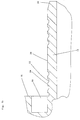
- FIG. 1b Scale A possible profile of the support sleeve 14 is enlarged in FIG. 1b Scale shown.
- the shape of the sealing or holding profiles 22, 24 is from this Presentation particularly well visible.
- the circumferential profiles 24 allow easier pushing on of the pipe and make pulling out more difficult of the pipe. This shape is essential for the actual sealing effect.
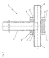
- FIG. 2 shows a further embodiment of a pipe connection 10 'according to to recognize the invention.
- the collar 12 borders respective support sleeves 14 on each side in the axial direction of the pipe connection 10 ′ on, with the left support sleeve 14 having a larger inner and outer diameter has as the right support sleeve.
- Recesses 16a, 16b offset from one another are provided, which provide a free Glimpse of the end face of the pushed-on pipe (not shown) the associated end face of the federal government 12, allow.
- the circumferential recess 18 becomes that on the pipe connection according to the invention 10 'tube to be fixed inserted.
- the profiling of the support sleeve 14 in this case preferably corresponds to that discussed in the discussion of FIG. 1 Design.
- a knee or elbow 10 is shown, which with an inventive trained pipe connection is provided.
- the federal government 12 according to the Embodiment 10 "goes directly into a corner or knee 40.
- This elbow 40 also has a right angle Line 42 on a connection between the opening of the support sleeve 14 and of the connection opening, into which a tube 44 fits into a tube seat 46 is.
- a solder ring insert 48 is inserted into the tube seat 46, which is used, after inserting the tube 44, for example a copper tube, Brass pipe or the like to be soldered or brazed.
- FIG. 4 shows a further embodiment 10 '' of the pipe connection according to to recognize the present invention.
- Right and left of a very wide designed collar 12 are pipe connection sections designed according to the invention with respective support sleeves 14, annular, circumferential recesses 18 and test openings or test recesses 16a, 16b.
- connection opening 62 incorporated, in which a connecting pipe 60 in turn, for example, via a Solder ring insert 64 can be soldered.
- a pipe is used, for example pushed onto the support sleeve 14 as shown in FIG. La, so that the end of the (not shown) tube in the circumferential recess 18 below the annular Extended section 16 sits on the collar 12. Then the press sleeve postponed so far that it is preferably on the end face of section 16 is present.
- the correct seat of the tube on the front side of the collar 12 can the openings or recesses 16a, 16b (see for example Fig. 2) before the Pressing the compression sleeve to be checked.
- the pressing process can be interrupted and the position of the tube and / or the compression sleeve can be corrected become.
- the correct position of the Pipe and / or the compression sleeve usually no longer, so that another No longer observe the correct position of the pipe and / or the compression sleeve would be required.
Landscapes
- Engineering & Computer Science (AREA)
- General Engineering & Computer Science (AREA)
- Mechanical Engineering (AREA)
- Mutual Connection Of Rods And Tubes (AREA)
- Branch Pipes, Bends, And The Like (AREA)
- Laminated Bodies (AREA)
Description
- Fig. 1a und b
- eine Ausführungsform gemäß der Erfindung in einer teilweisen Schnittdarstellung bzw. einer teilweisen Seitenansicht;
- Fig. 2
- eine weitere Ausführung gemäß der Erfindung in einer Schnittansicht sowie in zwei axialen Draufsichten;
- Fig. 3
- ein Winkel- bzw. Kniestück gemäß der vorliegenden Erfindung in einem Längsschnitt; und
- Fig. 4
- ein gemäß der Erfindung ausgebildetes T-Stück in einer längsschnittlichen Darstellung.
Claims (8)
- Rohrverbindungsanordnung (10, 10', 10", 10"'), insbesondere für Rohre mit mindestens einer Kunststoffschicht, vorzugsweise Verbundrohre, mit den folgenden Merkmalen:mit mindestens einem Anschlußbereich für das Rohr,mit mindestens einem Bund am Anschlußbereich, an den das Rohr ansetzbar ist,mit mindestens einer Stützhülse (14) am Anschlußbereich, auf die das Rohr aufschiebbar ist,mit einer Preßhülse, wobeider Bund (12) an seinem Außenumfang mindestens eine Ausnehmung (16a, 16b) bzw. Öffnung oder durchsichtigen Bereich oder dergleichen aufweist, die bzw. der an dem Ansatz- oder Anschlußbereich bzw. den Anschlußbereichen (14) zugeordneten Randbereich des Bundes (12) vorgesehen ist bzw. sind, so daß die Lage eines Rohres überprüfbar ist, wobeider Bund (12) einen parallel zur Zylindersymmetrieachse verlaufenden aus der Stirnfläche des Bundes (12) herausragenden Abschnitt (16) aufweist, entweder in der Form eines separaten ringförmigen Abschnittes oder in der Form eines mit dem Bund (12) einstückig ausgebildeten Abschnittes (16), wobei die Ausnehmung(en) bzw. Öffnung(en) in mindestens einem der Abschnitte vorgesehen ist, und wobeider herausragende Abschnitt (16) relativ zu der Preßhülse einen Durchmesser aufweist, so daß die Preßhülse an einer Stirnfläche des herausragenden Abschnitts anliegt.
- Rohrverbindung nach Anspruch 1, dadurch gekennzeichnet, daß der separate ringförmige Abschnitt wengistens bereichsweise aus einem durchsichtigen Material aufgebaut ist.
- Rohrverbindung nach einem der Ansprüche 1 oder 2, dadurch gekennzeichnet, daß der jeweilige Abschnitt (16) einen Innendurchmesser aufweist, der gegenüber dem Außendurchmesser des Anschlußbereichs bzw. der Stützhülse (14) so dimensioniert ist, daß ein anzuschließendes Rohr mit Spiel, vorzugsweise stramm, in den Zwischenraum einschiebbar ist.
- Rohrverbindung nach einem der Ansprüche 1 bis 3, dadurch gekennzeichnet, daß der Anschlußbereich bzw. die Stützhülse (14) an einem Bereich bzw. an Bereichen, an denen die Preßhülse in ihrer verpreßten Lage auf dem Anschlußbereich verpreßt ist, umfängliche Erhöhungen bzw. Vertiefungen (22, 24) aufweist.
- Rohrverbindung nach einem der Ansprüche 1 bis 4, dadurch gekennzeichnet, daß der Anschlußbereich bzw. die Stützhülse (14) an einem Bereich (26) bzw. an Bereichen (26), an denen die Preßhülse in ihrer verpreßten Lage auf dem Anschlußbereich bzw. der Stützhülse (14) unverpreßt ist, eine Rändelung, vorzugsweise mit vertieften Spitzen aufweist, wobei die Spitzen zueinander versetzt ausgebildet sind.
- Rohrverbindung nach einem der Ansprüche 1 bis 5, dadurch gekennzeichnet, daß zwei Ausnehmungen bzw. Öffnungen (16a, 16b) umfänglich um 180° zueinander versetzt angeordnet sind, bzw. daß die Preßhülse eine Montage-Verrutsch-Verhinderungseinrichtung bzw. eine Rutschbremse aufweist, die ggf. durch eine innen konische oder doppelkonische Ausbildung der Preßhülse ausgeführt ist, die in einem in Längsrichtung der Preßhülse mittleren Bereich eine Einschnürung ergibt oder die an einem oder beiden Endbereichen der Preßhülse jeweilige Einschnürungen ergibt, wobei diese Einschnürungen einen geringfügig geringeren Innendurchmesser aufweisen, als das zu der Preßhülse passend dimensionierte Rohr.
- Rohrverbindung nach Anspruch 6, dadurch gekennzeichnet, daß die Rutschbremse mindestens eine radial einwärts ausgerichtete Erstreckung aufweist.
- Rohrverbindung nach einem der Ansprüche 1 bis 7, dadurch gekennzeichnet, daß auf beiden Seiten des Bundes (12) jeweilige Anschlußbereiche bzw. Stützhülsen (14) mit gleichen oder unterschiedlichen Außen- und/oder Innendurchmessern vorgesehen sind, wobei insbesondere auf einer Seite des Bundes (12) ein Kniestück oder eine Schraubkupplung (20) oder dergleichen angeordnet sein kann, und bevorzugt in dem longitudinalen Bereich bzw. in die Breitseite des Bundes (12) der Rohrverbindung mindestens eine, beispielsweise eingelötete, eingepreßte oder eingeschweißte Metallrohrleitung (60, 44) eingesetzt ist.
Applications Claiming Priority (2)
| Application Number | Priority Date | Filing Date | Title |
|---|---|---|---|
| DE4441373A DE4441373C2 (de) | 1994-11-21 | 1994-11-21 | Rohrverbindung, insbesondere für Rohre mit mindestens einer Kunststoffschicht |
| DE4441373 | 1994-11-21 |
Publications (3)
| Publication Number | Publication Date |
|---|---|
| EP0713042A1 EP0713042A1 (de) | 1996-05-22 |
| EP0713042B1 true EP0713042B1 (de) | 1999-07-14 |
| EP0713042B2 EP0713042B2 (de) | 2003-08-20 |
Family
ID=6533754
Family Applications (1)
| Application Number | Title | Priority Date | Filing Date |
|---|---|---|---|
| EP95118296A Expired - Lifetime EP0713042B2 (de) | 1994-11-21 | 1995-11-21 | Verbundrohr-Verbindungsanordnung |
Country Status (3)
| Country | Link |
|---|---|
| EP (1) | EP0713042B2 (de) |
| AT (1) | ATE182203T1 (de) |
| DE (2) | DE4441373C2 (de) |
Cited By (1)
| Publication number | Priority date | Publication date | Assignee | Title |
|---|---|---|---|---|
| WO2001073330A2 (en) | 2000-03-27 | 2001-10-04 | Giacomini S.P.A. | Fitting for pressure coupling plastics pipes |
Families Citing this family (16)
| Publication number | Priority date | Publication date | Assignee | Title |
|---|---|---|---|---|
| EP0913612B1 (de) | 1997-11-03 | 2003-04-02 | NOVOPRESS GMBH PRESSEN UND PRESSWERKZEUGE & CO. KG. | Verfahren zum Verbinden eines Rohres mit einer Rohrkupplung, Verbindung zwischen einem Rohr und einer Rohrkupplung sowie Rohrkupplung hierfür |
| DE19749748C1 (de) * | 1997-11-03 | 1999-04-08 | Novopress Gmbh | Verfahren zum Verbinden eines Rohres mit einer Rohrkupplung, Verbindung zwischen einem Rohr und einer Rohrkupplung sowie Rohrkupplung hierfür |
| DE19748623B4 (de) * | 1997-11-04 | 2009-06-04 | Henco Industries Nv | Preßverbindung |
| AT2219U1 (de) * | 1997-12-22 | 1998-06-25 | Jaeggi Georg | Verpressbare rohrverbindung |
| FR2775508B1 (fr) | 1998-03-02 | 2000-04-14 | Comap Abbeville | Raccord a sertir pour un tuyau en matiere synthetique |
| DE19841801C1 (de) * | 1998-09-12 | 2000-05-04 | Hewing Gmbh | Fitting für ein Rohr |
| DE19854148A1 (de) * | 1998-11-24 | 2000-11-02 | Friatec Ag | Steckkupplung |
| DE19932718A1 (de) * | 1999-09-23 | 2001-05-23 | Friatec Ag | Steckkupplung |
| DE19935246B4 (de) | 1999-06-04 | 2004-07-22 | Friatec Ag | Steckverbinder |
| DE19956000C1 (de) * | 1999-11-20 | 2001-01-25 | Ivt Installations Und Verbindu | Klemmverbinder |
| DE10022893C1 (de) * | 2000-05-10 | 2001-06-28 | Schuetz Gmbh & Co Kgaa | Pressfitting für Kunststoff-Verbundrohre |
| GB2376510A (en) * | 2001-06-12 | 2002-12-18 | Peter Mcloughlin | Pipe connector with means for visual inspection |
| DE50100099D1 (de) | 2001-07-03 | 2003-03-13 | Polypress Rohrsysteme Gmbh | Anschlusselement |
| DE202005016258U1 (de) | 2005-10-11 | 2005-12-08 | Ipa Produktions- Und Vertriebsges.M.B.H. | Verbindungsanordnung für Rohre |
| DE102008039991B3 (de) | 2008-08-27 | 2009-10-29 | Kottmann Gosla Gmbh | Druckschlauch für ein wasserführendes System, insbesondere zum Anschließen von beweglichen Sanitärarmaturen oder zum Verbinden von Teilen des wasserführenden Systems |
| DE202009016975U1 (de) | 2009-12-16 | 2011-04-28 | Uponor Innovation Ab | Fitting für ein Rohr |
Family Cites Families (7)
| Publication number | Priority date | Publication date | Assignee | Title |
|---|---|---|---|---|
| US1926270A (en) * | 1932-08-13 | 1933-09-12 | Eastman Joseph Peter | Pressed-on hose coupling |
| US2177095A (en) * | 1936-02-15 | 1939-10-24 | Cowles Irving | Flexible conduit and coupling therefor and method of making same |
| US3885819A (en) † | 1972-11-21 | 1975-05-27 | Herbert Egerer | Compressed air hose connection |
| US5049745A (en) * | 1988-11-14 | 1991-09-17 | Amray, Inc. | Phase-compensating vibration cancellation system for scanning electron microscopes |
| JPH03186683A (ja) * | 1989-12-14 | 1991-08-14 | Sekisui Chem Co Ltd | 管継手 |
| DE9016310U1 (de) * | 1990-11-30 | 1991-02-21 | Hewing GmbH, 4434 Ochtrup | Rohrverbindung, insbesondere an Verbundrohren |
| DE9110998U1 (de) * | 1991-09-05 | 1991-10-31 | Hewing GmbH, 4434 Ochtrup | Rohrverbindung |
-
1994
- 1994-11-21 DE DE4441373A patent/DE4441373C2/de not_active Expired - Lifetime
-
1995
- 1995-11-21 DE DE59506383T patent/DE59506383D1/de not_active Expired - Lifetime
- 1995-11-21 EP EP95118296A patent/EP0713042B2/de not_active Expired - Lifetime
- 1995-11-21 AT AT95118296T patent/ATE182203T1/de active
Cited By (1)
| Publication number | Priority date | Publication date | Assignee | Title |
|---|---|---|---|---|
| WO2001073330A2 (en) | 2000-03-27 | 2001-10-04 | Giacomini S.P.A. | Fitting for pressure coupling plastics pipes |
Also Published As
| Publication number | Publication date |
|---|---|
| ATE182203T1 (de) | 1999-07-15 |
| DE4441373A1 (de) | 1996-05-23 |
| EP0713042B2 (de) | 2003-08-20 |
| EP0713042A1 (de) | 1996-05-22 |
| DE59506383D1 (de) | 1999-08-19 |
| DE4441373C2 (de) | 1997-12-04 |
Similar Documents
| Publication | Publication Date | Title |
|---|---|---|
| EP0713042B1 (de) | Rohrverbindung, insbesondere für Rohre mit mindestens einer Kunststoffschicht | |
| EP0501404B1 (de) | Anschlussvorrichtung für Kunststoffrohre und Verfahren zum Anschliessen eines Kunststoffrohres | |
| DE102008039446B4 (de) | Anordnung sowie Verfahren zur Herstellung einer unlösbaren Werkstückverbindung | |
| DE2911708C2 (de) | Rohrverbindungsanordnung, insbesondere für Gasrohrleitungsnetze oder dergleichen, und Verfahren und Vorrichtung zur Herstellung von derartigen Rohrverbindungsanordnungen | |
| DE19631574C1 (de) | Rohrverbindung | |
| DE3246327A1 (de) | Vorrichtung zur verbindung zweier rohrenden | |
| EP0883771A1 (de) | Rohrverbindung | |
| DE2521930C2 (de) | Rohrverbindungsstück | |
| DE60115413T2 (de) | Fitting für eine druckmittelkupplung für kunststoffrohre | |
| DE602005000499T2 (de) | Ring zur Prüfung der Verpressung eines Rohrpressfittings | |
| DE19929010C1 (de) | Kunststofformteil sowie Verbindungsvorrichtung mit diesem | |
| DE2610878A1 (de) | Rohrverbindung mit einer schraubmuffe | |
| DE9113050U1 (de) | Verbindung für Leitungsrohre | |
| EP0546405B1 (de) | Rohranschlussverbindung | |
| DE29908561U1 (de) | Kombination aus Fitting, Rohr und Preßgerät zum unlösbaren Verbinden eines Rohres mit einem Fitting | |
| DE202011003529U1 (de) | Vorrichtung zum Verbinden von Rohren | |
| DE19748937C1 (de) | Rohrverbindung | |
| DE9412445U1 (de) | Unlösbare Rohrverbindung | |
| DE9421958U1 (de) | Rohrverbindung, insbesondere für Rohre mit mindestens einer Kunststoffschicht | |
| DE10331381A1 (de) | Pressverbindung und Stützhülse für eine Pressverbindung | |
| DE4400283C1 (de) | Vorrichtung zum Verbinden eines Metallrohres mit einem Kunststoffrohr | |
| EP3492796B1 (de) | Verbindungssystem zur reparatur von kunststoffverbundrohrsystemen | |
| DE10013569C2 (de) | Rohrpressverbindung | |
| DE10026083C1 (de) | Rohrpressverbindung | |
| DE616085C (de) | Verbindung fuer Rohre u. dgl., bei der eine Klemmhuelse derart zwischen Druckgliedern angeordnet ist, dass ihre Enden den Druckgliedern anliegen und dass beim Schliessen er Verbindung die Klemmhuelse zusammengedrueckt und verformt wird |
Legal Events
| Date | Code | Title | Description |
|---|---|---|---|
| PUAI | Public reference made under article 153(3) epc to a published international application that has entered the european phase |
Free format text: ORIGINAL CODE: 0009012 |
|
| AK | Designated contracting states |
Kind code of ref document: A1 Designated state(s): AT BE CH DE FR IT LI LU NL |
|
| 17P | Request for examination filed |
Effective date: 19960402 |
|
| 17Q | First examination report despatched |
Effective date: 19970905 |
|
| GRAG | Despatch of communication of intention to grant |
Free format text: ORIGINAL CODE: EPIDOS AGRA |
|
| GRAG | Despatch of communication of intention to grant |
Free format text: ORIGINAL CODE: EPIDOS AGRA |
|
| GRAH | Despatch of communication of intention to grant a patent |
Free format text: ORIGINAL CODE: EPIDOS IGRA |
|
| RBV | Designated contracting states (corrected) |
Designated state(s): AT BE CH DE FR IT LI LU NL |
|
| GRAH | Despatch of communication of intention to grant a patent |
Free format text: ORIGINAL CODE: EPIDOS IGRA |
|
| GRAA | (expected) grant |
Free format text: ORIGINAL CODE: 0009210 |
|
| AK | Designated contracting states |
Kind code of ref document: B1 Designated state(s): AT BE CH DE FR IT LI LU NL |
|
| REF | Corresponds to: |
Ref document number: 182203 Country of ref document: AT Date of ref document: 19990715 Kind code of ref document: T |
|
| REG | Reference to a national code |
Ref country code: CH Ref legal event code: EP |
|
| REG | Reference to a national code |
Ref country code: CH Ref legal event code: NV Representative=s name: RIEDERER HASLER & PARTNER PATENTANWAELTE AG |
|
| REF | Corresponds to: |
Ref document number: 59506383 Country of ref document: DE Date of ref document: 19990819 |
|
| ET | Fr: translation filed | ||
| PLBQ | Unpublished change to opponent data |
Free format text: ORIGINAL CODE: EPIDOS OPPO |
|
| PLBI | Opposition filed |
Free format text: ORIGINAL CODE: 0009260 |
|
| PLBF | Reply of patent proprietor to notice(s) of opposition |
Free format text: ORIGINAL CODE: EPIDOS OBSO |
|
| 26 | Opposition filed |
Opponent name: IPA PRODUKTIONS- UND VERTRIEBSGESELLSCHAFT M.B.H. Effective date: 20000309 |
|
| NLR1 | Nl: opposition has been filed with the epo |
Opponent name: IPA PRODUKTIONS- UND VERTRIEBSGESELLSCHAFT M.B.H. |
|
| PLBF | Reply of patent proprietor to notice(s) of opposition |
Free format text: ORIGINAL CODE: EPIDOS OBSO |
|
| PLBF | Reply of patent proprietor to notice(s) of opposition |
Free format text: ORIGINAL CODE: EPIDOS OBSO |
|
| PLAW | Interlocutory decision in opposition |
Free format text: ORIGINAL CODE: EPIDOS IDOP |
|
| APAC | Appeal dossier modified |
Free format text: ORIGINAL CODE: EPIDOS NOAPO |
|
| APAE | Appeal reference modified |
Free format text: ORIGINAL CODE: EPIDOS REFNO |
|
| APAC | Appeal dossier modified |
Free format text: ORIGINAL CODE: EPIDOS NOAPO |
|
| APAC | Appeal dossier modified |
Free format text: ORIGINAL CODE: EPIDOS NOAPO |
|
| PLAW | Interlocutory decision in opposition |
Free format text: ORIGINAL CODE: EPIDOS IDOP |
|
| RTI2 | Title (correction) |
Free format text: CONNECTION ARRANGEMENT FOR COMPOSITE PIPES |
|
| PUAH | Patent maintained in amended form |
Free format text: ORIGINAL CODE: 0009272 |
|
| STAA | Information on the status of an ep patent application or granted ep patent |
Free format text: STATUS: PATENT MAINTAINED AS AMENDED |
|
| 27A | Patent maintained in amended form |
Effective date: 20030820 |
|
| AK | Designated contracting states |
Designated state(s): AT BE CH DE FR IT LI LU NL |
|
| REG | Reference to a national code |
Ref country code: CH Ref legal event code: AEN Free format text: AUFRECHTERHALTUNG DES PATENTES IN GEAENDERTER FORM |
|
| NLR2 | Nl: decision of opposition |
Effective date: 20030820 |
|
| NLR3 | Nl: receipt of modified translations in the netherlands language after an opposition procedure | ||
| ET3 | Fr: translation filed ** decision concerning opposition | ||
| APAH | Appeal reference modified |
Free format text: ORIGINAL CODE: EPIDOSCREFNO |
|
| REG | Reference to a national code |
Ref country code: CH Ref legal event code: PCAR Free format text: RIEDERER HASLER & PARTNER PATENTANWAELTE AG;ELESTASTRASSE 8;7310 BAD RAGAZ (CH) |
|
| REG | Reference to a national code |
Ref country code: DE Ref legal event code: R082 Ref document number: 59506383 Country of ref document: DE Representative=s name: WEICKMANN & WEICKMANN PATENT- UND RECHTSANWAEL, DE Ref country code: DE Ref legal event code: R082 Ref document number: 59506383 Country of ref document: DE Representative=s name: WEICKMANN & WEICKMANN PATENTANWAELTE - RECHTSA, DE Ref country code: DE Ref legal event code: R082 Ref document number: 59506383 Country of ref document: DE Representative=s name: PATENTANWAELTE WEICKMANN & WEICKMANN, DE |
|
| PGFP | Annual fee paid to national office [announced via postgrant information from national office to epo] |
Ref country code: LU Payment date: 20141121 Year of fee payment: 20 |
|
| PGFP | Annual fee paid to national office [announced via postgrant information from national office to epo] |
Ref country code: DE Payment date: 20140930 Year of fee payment: 20 Ref country code: CH Payment date: 20141119 Year of fee payment: 20 Ref country code: FR Payment date: 20141119 Year of fee payment: 20 |
|
| PGFP | Annual fee paid to national office [announced via postgrant information from national office to epo] |
Ref country code: AT Payment date: 20141120 Year of fee payment: 20 Ref country code: NL Payment date: 20141119 Year of fee payment: 20 |
|
| PGFP | Annual fee paid to national office [announced via postgrant information from national office to epo] |
Ref country code: IT Payment date: 20141125 Year of fee payment: 20 |
|
| PGFP | Annual fee paid to national office [announced via postgrant information from national office to epo] |
Ref country code: BE Payment date: 20141118 Year of fee payment: 20 |
|
| REG | Reference to a national code |
Ref country code: DE Ref legal event code: R071 Ref document number: 59506383 Country of ref document: DE |
|
| REG | Reference to a national code |
Ref country code: NL Ref legal event code: MK Effective date: 20151120 |
|
| REG | Reference to a national code |
Ref country code: CH Ref legal event code: PL |
|
| REG | Reference to a national code |
Ref country code: AT Ref legal event code: MK07 Ref document number: 182203 Country of ref document: AT Kind code of ref document: T Effective date: 20151121 |