EP0713045A1 - Rohrkupplung - Google Patents
Rohrkupplung Download PDFInfo
- Publication number
- EP0713045A1 EP0713045A1 EP95308116A EP95308116A EP0713045A1 EP 0713045 A1 EP0713045 A1 EP 0713045A1 EP 95308116 A EP95308116 A EP 95308116A EP 95308116 A EP95308116 A EP 95308116A EP 0713045 A1 EP0713045 A1 EP 0713045A1
- Authority
- EP
- European Patent Office
- Prior art keywords
- ring
- sealing ring
- anchor portion
- socket
- spigot end
- Prior art date
- Legal status (The legal status is an assumption and is not a legal conclusion. Google has not performed a legal analysis and makes no representation as to the accuracy of the status listed.)
- Withdrawn
Links
- 230000008878 coupling Effects 0.000 title description 3
- 238000010168 coupling process Methods 0.000 title description 3
- 238000005859 coupling reaction Methods 0.000 title description 3
- 238000007789 sealing Methods 0.000 claims abstract description 110
- 238000000034 method Methods 0.000 claims abstract description 17
- 238000004519 manufacturing process Methods 0.000 claims abstract description 11
- 229920000728 polyester Polymers 0.000 claims description 20
- 239000000463 material Substances 0.000 claims description 16
- 229920001971 elastomer Polymers 0.000 claims description 15
- 239000012530 fluid Substances 0.000 claims description 12
- 239000004927 clay Substances 0.000 claims description 11
- 238000000465 moulding Methods 0.000 claims description 6
- 229920002635 polyurethane Polymers 0.000 claims description 6
- 239000004814 polyurethane Substances 0.000 claims description 6
- 239000000806 elastomer Substances 0.000 claims description 5
- 239000004568 cement Substances 0.000 claims description 4
- 239000004567 concrete Substances 0.000 claims description 2
- 239000012768 molten material Substances 0.000 claims description 2
- 230000015572 biosynthetic process Effects 0.000 description 3
- 230000000694 effects Effects 0.000 description 3
- 238000005755 formation reaction Methods 0.000 description 3
- 238000003780 insertion Methods 0.000 description 3
- 230000037431 insertion Effects 0.000 description 3
- 230000004323 axial length Effects 0.000 description 2
- 238000007796 conventional method Methods 0.000 description 2
- 230000003247 decreasing effect Effects 0.000 description 2
- 241000555293 Bassariscus astutus Species 0.000 description 1
- 230000004308 accommodation Effects 0.000 description 1
- 239000000853 adhesive Substances 0.000 description 1
- 230000001070 adhesive effect Effects 0.000 description 1
- 230000006835 compression Effects 0.000 description 1
- 238000007906 compression Methods 0.000 description 1
- 230000009977 dual effect Effects 0.000 description 1
- 229920002457 flexible plastic Polymers 0.000 description 1
- 238000011065 in-situ storage Methods 0.000 description 1
- 239000007788 liquid Substances 0.000 description 1
- 238000012986 modification Methods 0.000 description 1
- 230000004048 modification Effects 0.000 description 1
- 230000000717 retained effect Effects 0.000 description 1
- 239000000126 substance Substances 0.000 description 1
Images

Classifications
-
- F—MECHANICAL ENGINEERING; LIGHTING; HEATING; WEAPONS; BLASTING
- F16—ENGINEERING ELEMENTS AND UNITS; GENERAL MEASURES FOR PRODUCING AND MAINTAINING EFFECTIVE FUNCTIONING OF MACHINES OR INSTALLATIONS; THERMAL INSULATION IN GENERAL
- F16L—PIPES; JOINTS OR FITTINGS FOR PIPES; SUPPORTS FOR PIPES, CABLES OR PROTECTIVE TUBING; MEANS FOR THERMAL INSULATION IN GENERAL
- F16L21/00—Joints with sleeve or socket
- F16L21/02—Joints with sleeve or socket with elastic sealing rings between pipe and sleeve or between pipe and socket, e.g. with rolling or other prefabricated profiled rings
- F16L21/03—Joints with sleeve or socket with elastic sealing rings between pipe and sleeve or between pipe and socket, e.g. with rolling or other prefabricated profiled rings placed in the socket before connection
-
- F—MECHANICAL ENGINEERING; LIGHTING; HEATING; WEAPONS; BLASTING
- F16—ENGINEERING ELEMENTS AND UNITS; GENERAL MEASURES FOR PRODUCING AND MAINTAINING EFFECTIVE FUNCTIONING OF MACHINES OR INSTALLATIONS; THERMAL INSULATION IN GENERAL
- F16L—PIPES; JOINTS OR FITTINGS FOR PIPES; SUPPORTS FOR PIPES, CABLES OR PROTECTIVE TUBING; MEANS FOR THERMAL INSULATION IN GENERAL
- F16L21/00—Joints with sleeve or socket
- F16L21/02—Joints with sleeve or socket with elastic sealing rings between pipe and sleeve or between pipe and socket, e.g. with rolling or other prefabricated profiled rings
- F16L21/035—Joints with sleeve or socket with elastic sealing rings between pipe and sleeve or between pipe and socket, e.g. with rolling or other prefabricated profiled rings placed around the spigot end before connection
Definitions
- the present invention relates to a pipe coupling. More particularly, but not exclusively, the invention relates to a pipe coupling suitable for use in conjunction with clay-based piping systems.
- These rings are normally formed from polyester or polyurethane and are moulded onto the spigot end and into the socket after the manufacture of the spigot and socket bodies. This is achieved by locating the spigot and/or socket mouth in an appropriate mould and filling with the polyester or polyurethane.
- the dimensions of the rings can be controlled much more accurately than the bodies of the spigot and socket, thereby improving the manufacturing tolerances of the spigot end and socket mouth as a whole. As a result, the two fit together much more closely, thereby providing a better joint.
- This sealing ring takes the form of a simple band which is accommodated within an annular recess provided in the external perimeter of the dimensioning ring provided about the spigot end.
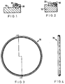
- An example of this is shown in Figure 1.
- polyester dimensioning ring 20 encircles the spigot end 10, onto which it is moulded.
- a rubber sealing band 30 fits within an external annular recess in the polyester ring 20. It is this rubber sealing band 30 which effects a seal between the spigot end and a socket into which the spigot end is inserted.
- the present invention therefore, sets out to provide an improved spigot end or socket, incorporating a dimensioning ring and a seal, wherein the arrangement is such as to deter an inappropriate sealing ring from being fitted.
- a spigot end or socket for a pipe comprising a coaxial dimensioning ring, and a sealing ring arranged coaxially with the dimensioning ring on an outer or inner surface thereof; wherein the sealing ring is at least partially embedded in the dimensioning ring.
- the dimensioning ring is factory moulded to the pipe spigot or socket and is formed from polyester or polyurethane.
- the sealing ring may be formed from rubber or some other elastomer.
- the pipe may be formed from clay, concrete or cement.
- the dimensioning ring is configured to encircle an axial end region of a spigot and the sealing ring comprises a radially inwardly projecting anchor portion and the dimensioning ring is moulded so as to surround the anchor portion at least partially.
- the anchor portion is annular and comprises one or more apertures extending axially therethrough, for allowing a through-flow of material for forming the dimensioning ring during a moulding process.
- the anchor portion is keyed to the dimensioning ring by a mechanical fixation. The mechanical fixation may be a snap-fit engagement.
- the anchor portion is axially off-set from a primary sealing surface of the sealing ring.
- the sealing ring is located with the anchor portion closer to the axial end of the pipe than is the said primary sealing surface.
- the anchor portion may be formed from a radially inner ring connected to a radially inner surface of a body portion of the sealing ring by a plurality of radially extending spokes, at least one of which may be a sprue.
- the radially inner ring may be in the form of a generally flat band.
- the sealing ring comprises a radially outwardly projecting anchor portion and the dimensioning ring is moulded so as to surround the anchor portion at least partially.
- the anchor portion is annular and comprises one or more apertures extending axially therethrough, for allowing a through-flow of material for forming the dimensioning ring during a moulding process.
- the anchor portion is axially off-set from a primary sealing surface of the sealing ring.
- the sealing ring is located with the anchor portion closer to the socket mouth than is the primary sealing surface.
- the anchor portion may be formed by a radially outer ring connected to a radially outer surface of a body portion of the sealing ring by a plurality of spokes, at least one of which may be a sprue.
- the radially outer ring may be a flat band.
- sealing ring is fixed to the dimensioning ring, it is not possible for a labourer to confuse sealing rings for different pipe dimensions.
- any fluid material which is to form the dimensioning ring can flow through and surround the anchor portion and, therefore, retain the sealing ring securely in place.
- the sealing ring can be used in conjunction with the general principles of known manufacturing techniques which will be described in detail below.
- the sealing ring By off-setting the primary sealing surface from the anchor portion in the axial direction, the sealing ring can offer a continuous resistance to radial deflection and, therefore, provide a uniform seal around the perimeter of the spigot or socket mouth. Furthermore, if the seal is damaged, the sealing ring can be torn from the dimensioning ring and the axial off-set, therefore, enables a replacement ring to be fitted without interference of any formations in the dimensioning ring caused by accommodation of the sealing ring during manufacturing.
- sealing ring for use in a spigot or socket as described above and including any or all of the features set out in relation thereto.
- the fluid material is polyester or polyurethane, but may be any other castable material (even such as cement), and the sealing ring is formed from an elastomer, such as rubber.
- the pipe end and sealing ring may be located concentrically within a mould during the manufacturing process.
- the mould may contain an annular recess on a bottom surface thereof, the recess being provided with an annular seal for preventing the passage of molten material past an end surface of the pipe end.
- a closure ring may be used to close a junction between the sealing ring and a wall of the mould.
- the sealing ring may be provided with a radially inwardly or outwardly directed anchor portion.
- the anchor portion may comprise apertures and the fluid material may be caused to flow through the apertures, so as to surround, at least partially, the anchor portion.
- the spigot comprises a clay pipe 10, a polyester dimensioning ring 20 and a rubber sealing ring 30.
- the dimensioning ring 20 may alternatively be formed from polyurethane. Any appropriate elastomer may be used for the sealing ring 30, in place of rubber.
- the clay pipe 10 is conventional and is provided with a stepped outer surface 11,12,13, defining regions of decreasing diameter in the axially mouthward direction. The regions of decreasing diameter 11,12,13 are connected by intermediate conical surfaces 14,15,16.
- Dimensioning ring 20 is moulded around the spigot end and combines readily with the stepped surfaces 11,12 and 13 to provide a secure attachment. Because the dimensioning ring 20 is moulded onto the spigot end, the radially outer surface 21 of the dimensioning ring 20 can be controlled to a high tolerance, thereby enabling a spigot having an accurately formed external diameter to be produced.
- Sealing ring 30 is moulded into the dimensioning ring 20 in a fixed fashion. It can be seen that the sealing ring 30 comprises a radially outer primary sealing surface 31, which is intended to effect a seal between the spigot and a socket.
- a radially inner surface 37 of the sealing ring 30 is provided with an anchor portion.
- the anchor portion is partly defined by an annular band 32.
- the cross-section of the band 32 has its longest side aligned axially and has somewhat rounded ends, these being generally semi-circular.
- the band 32 is connected to the radially inner surface 37 of the sealing ring 30 by a plurality of spokes 33.
- Each spoke 33 is circular in cross-section. In the embodiment of Figure 6, each spoke has a diameter which corresponds to the longest dimension of the cross-section of the band 32. In the embodiment of Figure 2, each spoke has a narrower diameter.
- the sealing ring 30, in each embodiment, is located with one axial end surface 36 generally flush with the mouth end surface 17 of the clay pipe.
- the intermediate dimensioning ring 20 also has one end surface 22 flush with surfaces 36 and 17, so as to present a single spigot end surface.
- Each sealing ring 30 also comprises a neck region 310 towards the spigot end.
- This neck region 310 leads into the remainder of the sealing ring body via a conical surface 34, which is inclined radially outwardly in the axially inward direction of the spigot end.
- This conical surface 34 is to facilitate insertion of the spigot end into the mouth of a socket. During insertion, the neck of the spigot initially fits easily within the socket until conical surface 34 is reached, when the sealing ring is gradually compressed with further insertion, so as to provide a good seal.
- the sealing ring 30 of the Figure 6 embodiment further comprises a tail 35, which is saw-toothed in cross-section. This tail serves to retain the axially innermost end of the sealing ring 30 in position within the contours of the dimensioning ring 20.
- the clay pipe end 10 is inserted into a greased mould 40.
- An O-ring 60 is seated in an annular recess in the bottom of the mould, so as to provide a good seal between the mould bottom and the spigot end surface 17.
- the sealing ring 30 is also inserted into the mould.
- the mould comprises wall portions 41 and 42 which are arranged to correspond generally with the external diameter of outer surfaces 31 and 38 of the sealing ring 30, so that the sealing ring is evenly supported within the mould.
- the mould 40 further comprises a rebate 43, in an upper region of its inner wall, which has a depth corresponding to the height of axially inner surface 39 of the sealing ring when located in position within the mould.
- the rebate 43 is for accommodating a greased closure ring 50, which has the dual purpose of defining a moulding surface for the radially outer surface of the dimensioning ring 20 and also for closing-off the junction between the radially outer surface 31 of the sealing ring 30 and the corresponding surface 42 of the mould, so as to prevent the passage of any liquid polyester.
- the height of the closure ring 50 corresponds with the required axial length of the dimensioning ring 20, so that surplus polyester can simply be skimmed off.
- fluid polyester can be poured into the cavity between the radially outer wall of the clay pipe spigot end and the radially inner walls of the sealing ring 30 and the closure ring 50 until the cavity is filled.
- the polyester sets to handling hardness within about one minute.
- the fluid polyester can flow through the gaps between the spokes and, therefore, completely surround the anchor ring 32 and the spokes 33. This ensures that the anchor ring 32 is completely embedded in the dimensioning ring 20 once it is formed. Furthermore, the sealing ring tail 35 is also retained securely within the dimensioning ring, due to the fact that fluid polyester flows downwards past it in the radially outer and axially outer directions.
- the clay pipe is lifted out of the mould and the closure ring 50 can be removed.
- the closure ring 50 is formed from PVC, and comprises a split, so as to define a 'c'-shape. Any appropriate semi-flexible plastic material may be used instead of PVC, however. As a result, it can be pushed over the sealing ring in the axially outer direction, with its removal being accommodated by its own deflection, so as to avoid damage to the sealing ring or polyester surface.
- the sealing ring 30 provides a good seal within a socket because the sealing surface 31 is firmly supported by the dimensioning ring over the majority of its axial length.
- the anchor portion of the sealing ring 30 is axially off-set from the primary sealing surface 31. If the sealing surface 31 and the anchor portion were not off-set in the axial direction, then the polyester, which is filled between the anchor ring 32 and the inner surface 37 of the sealing ring 30 might provide a firmer foundation for the primary sealing surface than the spoke portions 33 of the sealing ring, thereby providing uneven resistance to radial compression at regular circumferential intervals. This is, obviously, undesirable as it could lead to leakage.
- the sealing ring 30 can simply be ripped away from the outer surface of the dimensioning ring 20. When this is done, the anchor ring 32 is torn and can be extracted via apertures formed in the dimensioning ring 20 by the spokes 33 during the moulding process.
- a replacement seal can be fitted.
- the replacement seal can simply be a flat band or O-ring, such as used in conventional spigots, since such a seal can seat on the recessed outer diameter 23 formed in the dimensioning ring by the body of the sealing ring 30.
- the replacement seal can be provided with a series of radially inwardly projecting lugs corresponding to the arrangement, shape and size of the spokes of the sealing ring.
- the sealing ring could just as easily be provided in a dimensioning ring provided inside a socket mouth.
- the anchor portion is merely provided on a radially outer, rather than inner side of the sealing ring body. It can however, still be formed from a series of spokes and a flat band, exactly as set out above.
- the dimensioning ring need not, in either case, be moulded directly onto the pipe end. It could be affixed by some other means, such as deformation or by some intermediate substance such as an adhesive.
- the sealing ring could be mechanically fixed to the dimensioning ring instead. This will depend, to a large extent upon the materials used.
- the dimensioning ring and sealing ring could be formed with mutually co-operating formations such as lugs and recesses, enabling, in this case, a snap-fit engagement.
Landscapes
- Engineering & Computer Science (AREA)
- General Engineering & Computer Science (AREA)
- Mechanical Engineering (AREA)
- Joints With Sleeves (AREA)
- Gasket Seals (AREA)
Applications Claiming Priority (2)
| Application Number | Priority Date | Filing Date | Title |
|---|---|---|---|
| GB9423225 | 1994-11-17 | ||
| GB9423225A GB2295212A (en) | 1994-11-17 | 1994-11-17 | Pipe coupling |
Publications (1)
| Publication Number | Publication Date |
|---|---|
| EP0713045A1 true EP0713045A1 (de) | 1996-05-22 |
Family
ID=10764564
Family Applications (1)
| Application Number | Title | Priority Date | Filing Date |
|---|---|---|---|
| EP95308116A Withdrawn EP0713045A1 (de) | 1994-11-17 | 1995-11-14 | Rohrkupplung |
Country Status (3)
| Country | Link |
|---|---|
| EP (1) | EP0713045A1 (de) |
| DE (1) | DE713045T1 (de) |
| GB (1) | GB2295212A (de) |
Citations (6)
| Publication number | Priority date | Publication date | Assignee | Title |
|---|---|---|---|---|
| US2210833A (en) * | 1937-10-28 | 1940-08-06 | Gen Tire & Rubber Co | Sealing gasket |
| US2451070A (en) * | 1945-03-12 | 1948-10-12 | Us Stoneware Co | Fluid-retaining joint and method of making the same |
| US3493236A (en) * | 1965-05-15 | 1970-02-03 | Steinzeug U Kunststoffwarenfab | Socket pipe sealing assembly |
| DE3142637A1 (de) * | 1981-09-12 | 1983-05-05 | Denso-Chemie Wedekind Kg, 5090 Leverkusen | Pressring an einer dichtungsanordnung fuer eine muffenverbindung an rohren |
| FR2695589A1 (fr) * | 1992-09-15 | 1994-03-18 | Forsheda | Procédé de fabrication par moulage d'éléments creux tels que des éléments de canalisation en béton à joint d'étanchéité intégré, et dispositif pour la mise en Óoeuvre de ce procédé. |
| EP0588053A2 (de) * | 1992-09-04 | 1994-03-23 | Forsheda AB | Abdichtung zwischen zwei Teilen, insbesondere zwischen Betonrohren |
Family Cites Families (6)
| Publication number | Priority date | Publication date | Assignee | Title |
|---|---|---|---|---|
| GB1338555A (en) * | 1969-12-16 | 1973-11-28 | Oates P C | Internal joint seals for pipes conduits and the like |
| GB1240808A (en) * | 1970-05-08 | 1971-07-28 | Hepworth Iron Co Ltd | Improvements in or relating to pipe couplings |
| GB1343602A (en) * | 1970-11-23 | 1974-01-16 | Press W & Son Ltd | Sealing pipe joints |
| US4108481A (en) * | 1976-12-06 | 1978-08-22 | United States Pipe And Foundry Company | Gasketed pipe joint |
| GB2181201B (en) * | 1985-09-30 | 1989-12-20 | Hepworth Iron Co Ltd | Coupling pipes |
| GB2217418B (en) * | 1988-04-16 | 1992-09-16 | Caswick Dev Ltd | Conduit sections with plastics connectors |
-
1994
- 1994-11-17 GB GB9423225A patent/GB2295212A/en not_active Withdrawn
-
1995
- 1995-11-14 DE DE1995308116 patent/DE713045T1/de active Pending
- 1995-11-14 EP EP95308116A patent/EP0713045A1/de not_active Withdrawn
Patent Citations (6)
| Publication number | Priority date | Publication date | Assignee | Title |
|---|---|---|---|---|
| US2210833A (en) * | 1937-10-28 | 1940-08-06 | Gen Tire & Rubber Co | Sealing gasket |
| US2451070A (en) * | 1945-03-12 | 1948-10-12 | Us Stoneware Co | Fluid-retaining joint and method of making the same |
| US3493236A (en) * | 1965-05-15 | 1970-02-03 | Steinzeug U Kunststoffwarenfab | Socket pipe sealing assembly |
| DE3142637A1 (de) * | 1981-09-12 | 1983-05-05 | Denso-Chemie Wedekind Kg, 5090 Leverkusen | Pressring an einer dichtungsanordnung fuer eine muffenverbindung an rohren |
| EP0588053A2 (de) * | 1992-09-04 | 1994-03-23 | Forsheda AB | Abdichtung zwischen zwei Teilen, insbesondere zwischen Betonrohren |
| FR2695589A1 (fr) * | 1992-09-15 | 1994-03-18 | Forsheda | Procédé de fabrication par moulage d'éléments creux tels que des éléments de canalisation en béton à joint d'étanchéité intégré, et dispositif pour la mise en Óoeuvre de ce procédé. |
Also Published As
| Publication number | Publication date |
|---|---|
| GB9423225D0 (en) | 1995-01-04 |
| DE713045T1 (de) | 1996-12-12 |
| GB2295212A (en) | 1996-05-22 |
Similar Documents
| Publication | Publication Date | Title |
|---|---|---|
| CA1073938A (en) | Molded pleated gasket | |
| EP1105669B1 (de) | Rohrdichtung mit eingelassenem ring | |
| US3973783A (en) | Pipe joint sealing device | |
| US4641858A (en) | Gasket incorporating implants for interfitting pipes | |
| US20090200705A1 (en) | Method of Manufacturing a Pipe Gasket | |
| US4186931A (en) | Pipe end sealing system | |
| US4565381A (en) | Self aligning concrete pipe with configured joint | |
| US3874063A (en) | Method of pipe joint sealing | |
| EA008546B1 (ru) | Вкладыш доильного стакана и доильный стакан | |
| CN1242688A (zh) | 挤奶杯内套及其制造方法 | |
| CA2518333C (en) | Pipe joint gasket | |
| GB2295212A (en) | Pipe coupling | |
| EP0896175A2 (de) | Dichtungselement | |
| US10603818B2 (en) | Method and apparatus for producing a sewer pipe element | |
| EP1222418B1 (de) | Verbindungsstück | |
| JPH076592B2 (ja) | 管用シールおよび保護装置 | |
| US4583771A (en) | Concrete pipe | |
| EP1626848B1 (de) | Unterring für ein formwerkzeug zum giessen eines betonrohrs mit teilweise eingebettetem kautschukband | |
| US6491066B1 (en) | Resilient bevel for profile wall pipe | |
| US7703474B2 (en) | Gate valve sealing structure | |
| KR19990071779A (ko) | 물꼭지카트리지용앵커유지팩킹을가진플러그 | |
| US3151195A (en) | Method and apparatus for making pipe joint sealing structures | |
| US4554772A (en) | Boot guard for sewer manhole construction | |
| GB1595692A (en) | Socket end pipes | |
| EP1627171B1 (de) | Gummileiste zur teilweisen einbettung in ein betonrohr, betonrohr mit teilweise eingebetteter gummileiste |
Legal Events
| Date | Code | Title | Description |
|---|---|---|---|
| PUAI | Public reference made under article 153(3) epc to a published international application that has entered the european phase |
Free format text: ORIGINAL CODE: 0009012 |
|
| AK | Designated contracting states |
Kind code of ref document: A1 Designated state(s): BE DE IT NL |
|
| ITCL | It: translation for ep claims filed |
Representative=s name: MARIETTI E GISLON S.R.L. |
|
| TCNL | Nl: translation of patent claims filed | ||
| 17P | Request for examination filed |
Effective date: 19960920 |
|
| DET | De: translation of patent claims | ||
| 17Q | First examination report despatched |
Effective date: 19980921 |
|
| STAA | Information on the status of an ep patent application or granted ep patent |
Free format text: STATUS: THE APPLICATION IS DEEMED TO BE WITHDRAWN |
|
| 18D | Application deemed to be withdrawn |
Effective date: 19990202 |