EP0713046A1 - Dispositif de silencieux pour tuyaux - Google Patents
Dispositif de silencieux pour tuyaux Download PDFInfo
- Publication number
- EP0713046A1 EP0713046A1 EP95117434A EP95117434A EP0713046A1 EP 0713046 A1 EP0713046 A1 EP 0713046A1 EP 95117434 A EP95117434 A EP 95117434A EP 95117434 A EP95117434 A EP 95117434A EP 0713046 A1 EP0713046 A1 EP 0713046A1
- Authority
- EP
- European Patent Office
- Prior art keywords
- chamber
- pipe
- cover cap
- pipe section
- resonator
- Prior art date
- Legal status (The legal status is an assumption and is not a legal conclusion. Google has not performed a legal analysis and makes no representation as to the accuracy of the status listed.)
- Granted
Links
Images


Classifications
-
- F—MECHANICAL ENGINEERING; LIGHTING; HEATING; WEAPONS; BLASTING
- F16—ENGINEERING ELEMENTS AND UNITS; GENERAL MEASURES FOR PRODUCING AND MAINTAINING EFFECTIVE FUNCTIONING OF MACHINES OR INSTALLATIONS; THERMAL INSULATION IN GENERAL
- F16L—PIPES; JOINTS OR FITTINGS FOR PIPES; SUPPORTS FOR PIPES, CABLES OR PROTECTIVE TUBING; MEANS FOR THERMAL INSULATION IN GENERAL
- F16L55/00—Devices or appurtenances for use in, or in connection with, pipes or pipe systems
- F16L55/02—Energy absorbers; Noise absorbers
- F16L55/033—Noise absorbers
-
- F—MECHANICAL ENGINEERING; LIGHTING; HEATING; WEAPONS; BLASTING
- F01—MACHINES OR ENGINES IN GENERAL; ENGINE PLANTS IN GENERAL; STEAM ENGINES
- F01N—GAS-FLOW SILENCERS OR EXHAUST APPARATUS FOR MACHINES OR ENGINES IN GENERAL; GAS-FLOW SILENCERS OR EXHAUST APPARATUS FOR INTERNAL-COMBUSTION ENGINES
- F01N1/00—Silencing apparatus characterised by method of silencing
- F01N1/02—Silencing apparatus characterised by method of silencing by using resonance
-
- F—MECHANICAL ENGINEERING; LIGHTING; HEATING; WEAPONS; BLASTING
- F01—MACHINES OR ENGINES IN GENERAL; ENGINE PLANTS IN GENERAL; STEAM ENGINES
- F01N—GAS-FLOW SILENCERS OR EXHAUST APPARATUS FOR MACHINES OR ENGINES IN GENERAL; GAS-FLOW SILENCERS OR EXHAUST APPARATUS FOR INTERNAL-COMBUSTION ENGINES
- F01N1/00—Silencing apparatus characterised by method of silencing
- F01N1/08—Silencing apparatus characterised by method of silencing by reducing exhaust energy by throttling or whirling
- F01N1/084—Silencing apparatus characterised by method of silencing by reducing exhaust energy by throttling or whirling the exhaust gases flowing through the silencer two or more times longitudinally in opposite directions, e.g. using parallel or concentric tubes
-
- F—MECHANICAL ENGINEERING; LIGHTING; HEATING; WEAPONS; BLASTING
- F01—MACHINES OR ENGINES IN GENERAL; ENGINE PLANTS IN GENERAL; STEAM ENGINES
- F01N—GAS-FLOW SILENCERS OR EXHAUST APPARATUS FOR MACHINES OR ENGINES IN GENERAL; GAS-FLOW SILENCERS OR EXHAUST APPARATUS FOR INTERNAL-COMBUSTION ENGINES
- F01N2490/00—Structure, disposition or shape of gas-chambers
- F01N2490/20—Chambers being formed inside the exhaust pipe without enlargement of the cross section of the pipe, e.g. resonance chambers
Definitions
- the invention relates to a device for sound insulation in pipelines, which is based on a resonance silencer arranged within a chamber.
- the chamber is installed in a sound-conducting pipeline, which projects into the chamber with a pipe section on the inlet side and is connected to an outlet opening in the chamber at the chamber outlet.
- a special type of resonator is the so-called pipe resonator, the mode of operation of which is based on an interference between the incoming sound wave in a pipe and a reflected sound wave. The reflection takes place in a resonator chamber coupled to the pipeline.
- sound waves below the cut-off frequency of the channel which are given by their geometrical transverse dimensions, propagate as a progressive, flat wave. If there is a discontinuity in the channel, e.g. a sudden cross-sectional jump, stub line, etc., the incident sound wave is partially or completely reflected due to the change in impedance.
- There is sound insulation, such as z. B. is present on a wall.
- silencers e.g. Absorption silencers, as described in DE 35 09 033, work in the high-frequency range; however, these can only be used with severe restrictions, especially with moist or product-laden media.
- the task was therefore to develop a resonance silencer whose upper limit frequency is independent of the pipe dimensions and which at the same time brings about significant level reductions without the use of absorption material.
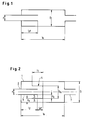
- the upper cut-off frequency f og of the pipe resonator is no longer dependent on the largest transverse dimension and thus on the diameter D of the chamber. Rather, the upper limit frequency is determined by the diameter d of the pipeline and by the clear width d k of the ring channel between the outer surface of the cap and the pipe section projecting into the chamber.
- the parameters d or d k meet the two conditions mentioned above. Particularly good results are achieved if the clear width d s of the annular gap between the cover cap and the inner wall of the chamber matches the clear width d k of the ring channel between the cover cap and the pipe section.
- the optimal distance l pf between the cover cap and the mouth of the pipe section is dimensioned in the same way as with a conventional pipe resonator, taking into account the mouth correction.
- the length l1 of the annular gap is twice the distance l pf between the mouth of the pipe section and the cap.
- the walls of the cover cap need not be solid. They can also consist of perforated sheets.
- the cap surface can also be slightly curved. In this case the resonance maximum is broadened somewhat, which is desirable in many cases.
- the silencer according to the invention is preferably combined with pipe resonators in a known construction.
- a pipe piece projecting into the chamber is also attached to the chamber outlet.
- a preferred combination with absorption mufflers can also achieve a broadband effect and also an additional improvement in the high-frequency range.
- Another preferred variant is the combination with a Helmholtz resonator.
- This variant can be implemented in such a way that a Helmholtz resonator which is matched to the sound frequency of the sound waves to be insulated is arranged between the two pipe resonators. With a suitable dimensioning, a broadband frequency range can also be insulated here.
- the pipe resonators are preferably arranged in parallel in a common chamber.
- the chamber is provided with a partition into which one or more pipe pieces connected in parallel with covering caps are installed.
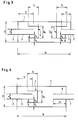
- FIG. 3 shows the connection in series of two muffler systems, each consisting of a pipe section 3 and a cover cap 4 in a common chamber 1.
- the two muffler systems can be dimensioned the same or different from the embodiment described above (FIG. 2) .
- the tube piece 3 projecting into the chamber 1 is equipped with a cap 4 and dimensioned as described above.
- the pipe section 8 connected to the continued part 7 of the pipeline projects into the chamber 1, so that a conventional pipe resonator is formed in combination with the preceding silencer.
- the additional resonance frequencies of the conventional pipe resonator are set, in which an insulation is to take place.
- Fig. 5 also shows a conventional pipe resonator with a pipe section 8 which protrudes into the pipe resonator chamber 9.
- the pipe resonator chamber 9 is connected directly to the chamber 1.
- the pipe piece 3 protruding into the chamber 1 is again equipped with a cover cap 4 and how dimensioned as described above. With the help of the length l3 of the pipe section 8 additional resonance frequencies are set at which damping is to take place.
- FIG. 6 shows a possible combination of the muffler system, consisting of the pipe section 3 and the cover cap 4, with an absorption muffler 10, which connects to the chamber outlet in a known manner.
- the absorption muffler 10 is arranged in the chamber 1 between the cover caps 4 of two successive resonance mufflers.
- FIG. 8 shows a particularly effective combination of the muffler according to the invention with a Helmholtz resonator.
- the Helmholtz resonator 11 is arranged here between the two cover caps 4.
- An embodiment deviating from conventional Helmholtz resonators has been described in DE 42 10 786. This design has also proven itself particularly well in the present case.
- FIG. 9 Another embodiment of the invention is shown in FIG. 9.
- the chamber 1 is here provided with a partition 12, into which a plurality of pipe pieces 3 connected in parallel with covering caps 4 are installed.
- This variant has the advantage that the free flow cross section can be dimensioned as desired in order to bring about a reduction in the flow speed and thus in the pressure losses.
- the exemplary embodiments described above relate to round pipelines and chambers.
- the sound insulation according to the invention can also be used, at least in the case of manhole-shaped pipes with a square or almost square cross section.
- the diameter of the shaft then takes the place of the diameter and the largest transverse dimension of the chamber installed in the sound-conducting shaft.
Landscapes
- Engineering & Computer Science (AREA)
- General Engineering & Computer Science (AREA)
- Mechanical Engineering (AREA)
- Chemical & Material Sciences (AREA)
- Combustion & Propulsion (AREA)
- Pipe Accessories (AREA)
- Exhaust Silencers (AREA)
- Catching Or Destruction (AREA)
- Soundproofing, Sound Blocking, And Sound Damping (AREA)
- Rigid Pipes And Flexible Pipes (AREA)
- Branch Pipes, Bends, And The Like (AREA)
Applications Claiming Priority (2)
| Application Number | Priority Date | Filing Date | Title |
|---|---|---|---|
| DE4440918 | 1994-11-17 | ||
| DE4440918A DE4440918A1 (de) | 1994-11-17 | 1994-11-17 | Vorrichtung zur Schalldämmung in Rohrleitungen |
Publications (2)
| Publication Number | Publication Date |
|---|---|
| EP0713046A1 true EP0713046A1 (fr) | 1996-05-22 |
| EP0713046B1 EP0713046B1 (fr) | 2001-02-21 |
Family
ID=6533465
Family Applications (1)
| Application Number | Title | Priority Date | Filing Date |
|---|---|---|---|
| EP95117434A Expired - Lifetime EP0713046B1 (fr) | 1994-11-17 | 1995-11-06 | Dispositif de silencieux pour tuyaux |
Country Status (6)
| Country | Link |
|---|---|
| US (1) | US5677518A (fr) |
| EP (1) | EP0713046B1 (fr) |
| AT (1) | ATE199279T1 (fr) |
| DE (2) | DE4440918A1 (fr) |
| DK (1) | DK0713046T3 (fr) |
| ES (1) | ES2154314T3 (fr) |
Cited By (1)
| Publication number | Priority date | Publication date | Assignee | Title |
|---|---|---|---|---|
| EP2362076A3 (fr) * | 2010-02-18 | 2012-05-16 | J. Eberspächer GmbH & Co. KG | Amortisseur de bruit |
Families Citing this family (15)
| Publication number | Priority date | Publication date | Assignee | Title |
|---|---|---|---|---|
| US5929396A (en) * | 1997-07-29 | 1999-07-27 | Awad; Elias A. | Noise reducing diffuser |
| JP2000230413A (ja) * | 1999-02-09 | 2000-08-22 | Honda Motor Co Ltd | 内燃機関の消音装置 |
| DE19956166B4 (de) * | 1999-11-23 | 2011-02-17 | Umfotec Gmbh | Ringkammerdämpfer |
| FR2824383B1 (fr) * | 2001-05-04 | 2007-05-11 | Mecaplast Sa | Dispositif d'attenuation du niveau sonore d'un circuit de fluide gazeux |
| JP4392592B2 (ja) * | 2003-12-12 | 2010-01-06 | トヨタ自動車株式会社 | 排気消音装置 |
| JP3944183B2 (ja) * | 2004-04-01 | 2007-07-11 | 本田技研工業株式会社 | 車両の排気系支持構造 |
| KR100710342B1 (ko) * | 2006-02-07 | 2007-04-23 | 엘지전자 주식회사 | 소음기 |
| US20110005860A1 (en) * | 2009-07-13 | 2011-01-13 | Kwin Abram | Exhaust component with reduced pack |
| US8978819B2 (en) * | 2013-06-07 | 2015-03-17 | Yamaha Hatsudoki Kabushiki Kaisha | Spark arrestor, muffler, and straddle type vehicle |
| KR20180053859A (ko) * | 2016-11-14 | 2018-05-24 | 엘지전자 주식회사 | 리니어 압축기 |
| US11883358B2 (en) | 2018-03-05 | 2024-01-30 | Leggett & Platt Canada Co. | Pneumatic massage system |
| US11039975B2 (en) | 2018-08-29 | 2021-06-22 | Leggett & Platt Canada Co. | Pneumatic massage |
| JP7271707B2 (ja) * | 2019-03-20 | 2023-05-11 | レゲット・アンド・プラット・カナダ・カンパニー | 空気圧システムの流体スイッチングモジュールのためのノイズ減衰器 |
| EP4110649A1 (fr) | 2020-02-24 | 2023-01-04 | Schukra Berndorf GmbH | Agencement de vessie pneumatique pour un siège et son procédé de fabrication |
| CN114215669A (zh) * | 2021-12-24 | 2022-03-22 | 安徽江淮汽车集团股份有限公司 | 一种消除进气宽频噪声的方法及扩张腔结构 |
Citations (7)
| Publication number | Priority date | Publication date | Assignee | Title |
|---|---|---|---|---|
| US1514441A (en) * | 1923-10-25 | 1924-11-04 | Arthur J Culp | Exhaust trap |
| US2043030A (en) | 1935-04-02 | 1936-06-02 | Maxim Silencer Co | Sound attenuating device |
| US2075265A (en) | 1935-08-09 | 1937-03-30 | Maxim Silencer Co | Sound attenuating device |
| US2218959A (en) * | 1940-02-29 | 1940-10-22 | Harlan W Sarvis | Exhaust silencer |
| DE3509033A1 (de) | 1985-03-13 | 1986-09-18 | Müller - BBM GmbH, 8033 Planegg | Schalldaempfer |
| DE4210786A1 (de) | 1992-04-01 | 1993-10-07 | Bayer Ag | Schalldämpfender Resonator für Rohrleitungen |
| DE4243280A1 (de) | 1992-12-21 | 1994-06-23 | Bayer Ag | Vorrichtung zur Schalldämpfung an Rohrleitungen |
Family Cites Families (8)
| Publication number | Priority date | Publication date | Assignee | Title |
|---|---|---|---|---|
| US1665005A (en) * | 1926-08-19 | 1928-04-03 | Newport Co | Method for the separation of m-dinitrobenzene from its isomers |
| US2100655A (en) * | 1935-08-09 | 1937-11-30 | Maxim Silencer Co | Sound attenuating device |
| GB493538A (en) * | 1936-06-22 | 1938-10-10 | Solex | Improvements in and relating to devices for deadening noise in a partially closed conduit |
| US3498406A (en) * | 1967-09-26 | 1970-03-03 | Walker Mfg Co | Triflow muffler for exhaust gases |
| US4022291A (en) * | 1975-11-21 | 1977-05-10 | Outboard Marine Corporation | Exhaust muffler having an attenuater can assembly |
| GB1537299A (en) * | 1976-11-12 | 1978-12-29 | Moss L | Exhaust silencers |
| SU945583A1 (ru) * | 1980-06-19 | 1982-07-23 | за вители | Глушитель шума |
| SU1564458A1 (ru) * | 1988-01-04 | 1990-05-15 | Сахалинский Государственный Научно-Исследовательский И Проектный Институт Газовой Промышленности | Устройство дл гашени кинетической энергии потока |
-
1994
- 1994-11-17 DE DE4440918A patent/DE4440918A1/de not_active Withdrawn
-
1995
- 1995-11-06 ES ES95117434T patent/ES2154314T3/es not_active Expired - Lifetime
- 1995-11-06 EP EP95117434A patent/EP0713046B1/fr not_active Expired - Lifetime
- 1995-11-06 AT AT95117434T patent/ATE199279T1/de not_active IP Right Cessation
- 1995-11-06 DK DK95117434T patent/DK0713046T3/da active
- 1995-11-06 DE DE59509031T patent/DE59509031D1/de not_active Expired - Fee Related
- 1995-11-13 US US08/556,129 patent/US5677518A/en not_active Expired - Fee Related
Patent Citations (7)
| Publication number | Priority date | Publication date | Assignee | Title |
|---|---|---|---|---|
| US1514441A (en) * | 1923-10-25 | 1924-11-04 | Arthur J Culp | Exhaust trap |
| US2043030A (en) | 1935-04-02 | 1936-06-02 | Maxim Silencer Co | Sound attenuating device |
| US2075265A (en) | 1935-08-09 | 1937-03-30 | Maxim Silencer Co | Sound attenuating device |
| US2218959A (en) * | 1940-02-29 | 1940-10-22 | Harlan W Sarvis | Exhaust silencer |
| DE3509033A1 (de) | 1985-03-13 | 1986-09-18 | Müller - BBM GmbH, 8033 Planegg | Schalldaempfer |
| DE4210786A1 (de) | 1992-04-01 | 1993-10-07 | Bayer Ag | Schalldämpfender Resonator für Rohrleitungen |
| DE4243280A1 (de) | 1992-12-21 | 1994-06-23 | Bayer Ag | Vorrichtung zur Schalldämpfung an Rohrleitungen |
Non-Patent Citations (2)
| Title |
|---|
| B.H. SCHMIDT: "Schalltechnisches Taschenbuch", 1989 |
| ZEITSCHRIFT FUER LAERMBEKAEMPFUNG, vol. 40, 1993, pages 99 - 102 |
Cited By (2)
| Publication number | Priority date | Publication date | Assignee | Title |
|---|---|---|---|---|
| EP2362076A3 (fr) * | 2010-02-18 | 2012-05-16 | J. Eberspächer GmbH & Co. KG | Amortisseur de bruit |
| US8302732B2 (en) | 2010-02-18 | 2012-11-06 | J. Eberspaecher Gmbh & Co. Kg | Silencer |
Also Published As
| Publication number | Publication date |
|---|---|
| ES2154314T3 (es) | 2001-04-01 |
| ATE199279T1 (de) | 2001-03-15 |
| DE59509031D1 (de) | 2001-03-29 |
| US5677518A (en) | 1997-10-14 |
| DE4440918A1 (de) | 1996-05-23 |
| EP0713046B1 (fr) | 2001-02-21 |
| DK0713046T3 (da) | 2001-03-19 |
Similar Documents
| Publication | Publication Date | Title |
|---|---|---|
| EP0713046B1 (fr) | Dispositif de silencieux pour tuyaux | |
| EP1395743B2 (fr) | Silencieux | |
| DE2920278A1 (de) | Verfahren und einrichtung zur schalldaempfung in insbesondere gasfoermigen ausbreitungsmedien | |
| EP1715189A1 (fr) | Silencieux développé pour et destiné à un compresseur | |
| DE10331620A1 (de) | Vorrichtung zur Geräuschgestaltung bei einem Kraftfahrzeug | |
| DE112017000469T5 (de) | Schalldämpfer | |
| EP1510667A2 (fr) | Silencieux | |
| DE2131410C3 (de) | Schalldämpfer, insbesondere für lufttechnische Anlagen | |
| DE2908506C2 (de) | Schalldämpfer für Verbrennungskraftmaschinen | |
| DE2706957C2 (de) | Abgasschalldämpfer | |
| DE3034575C2 (fr) | ||
| DE1299647B (de) | Schalldaempfendes Gasleitrohr | |
| DE3641942C2 (fr) | ||
| DE2309571A1 (de) | Auspuff-schalldaempfer fuer zweitaktmotore | |
| DE2714100A1 (de) | Luftansaugrohr fuer eine brennkraftmaschine | |
| EP0563706B1 (fr) | Résonateur atténuant le son pour tuyauteries | |
| DE2856889A1 (de) | Schalldaempfer in der abgasleitung eines verbrennungsmotors, insbesondere an einem kraftfahrzeug | |
| DE2738601C2 (de) | Schalldämpfer | |
| EP0163024B1 (fr) | Silencieux d'échappement à réflexion | |
| DE10103739B4 (de) | Schalldämpfer | |
| DE2930668A1 (de) | Vorrichtung zur reduzierung der ansaug- und/oder auspuffgeraeusche fuer schnellaufende brennkraftmaschinen, insbesondere fuer brennkraftmaschinenangetriebene kettensaegen, rasenmaeher und kleinkraftraeder | |
| DE4300117C2 (de) | Vorrichtung zur Schalldämmung in gasführenden Rohrleitungen oder Kanälen | |
| EP0719975A1 (fr) | Dispositif d'amortissement de son à la fin de tuyauteries | |
| EP0158013A1 (fr) | Silencieux à réflexion pour moteur à combustion | |
| DE884434C (de) | Schalldaempfer, insbesondere fuer Brennkraftmaschinen |
Legal Events
| Date | Code | Title | Description |
|---|---|---|---|
| PUAI | Public reference made under article 153(3) epc to a published international application that has entered the european phase |
Free format text: ORIGINAL CODE: 0009012 |
|
| AK | Designated contracting states |
Kind code of ref document: A1 Designated state(s): AT BE CH DE DK ES FR GB IT LI NL SE |
|
| 17P | Request for examination filed |
Effective date: 19961105 |
|
| 17Q | First examination report despatched |
Effective date: 19990701 |
|
| GRAG | Despatch of communication of intention to grant |
Free format text: ORIGINAL CODE: EPIDOS AGRA |
|
| GRAG | Despatch of communication of intention to grant |
Free format text: ORIGINAL CODE: EPIDOS AGRA |
|
| GRAH | Despatch of communication of intention to grant a patent |
Free format text: ORIGINAL CODE: EPIDOS IGRA |
|
| GRAH | Despatch of communication of intention to grant a patent |
Free format text: ORIGINAL CODE: EPIDOS IGRA |
|
| GRAA | (expected) grant |
Free format text: ORIGINAL CODE: 0009210 |
|
| AK | Designated contracting states |
Kind code of ref document: B1 Designated state(s): AT BE CH DE DK ES FR GB IT LI NL SE |
|
| REF | Corresponds to: |
Ref document number: 199279 Country of ref document: AT Date of ref document: 20010315 Kind code of ref document: T |
|
| REG | Reference to a national code |
Ref country code: CH Ref legal event code: EP |
|
| REG | Reference to a national code |
Ref country code: CH Ref legal event code: NV Representative=s name: E. BLUM & CO. PATENTANWAELTE |
|
| REG | Reference to a national code |
Ref country code: DK Ref legal event code: T3 |
|
| GBT | Gb: translation of ep patent filed (gb section 77(6)(a)/1977) |
Effective date: 20010223 |
|
| REF | Corresponds to: |
Ref document number: 59509031 Country of ref document: DE Date of ref document: 20010329 |
|
| REG | Reference to a national code |
Ref country code: ES Ref legal event code: FG2A Ref document number: 2154314 Country of ref document: ES Kind code of ref document: T3 |
|
| ITF | It: translation for a ep patent filed | ||
| ET | Fr: translation filed | ||
| PLBE | No opposition filed within time limit |
Free format text: ORIGINAL CODE: 0009261 |
|
| STAA | Information on the status of an ep patent application or granted ep patent |
Free format text: STATUS: NO OPPOSITION FILED WITHIN TIME LIMIT |
|
| REG | Reference to a national code |
Ref country code: GB Ref legal event code: IF02 |
|
| 26N | No opposition filed | ||
| PGFP | Annual fee paid to national office [announced via postgrant information from national office to epo] |
Ref country code: FR Payment date: 20051026 Year of fee payment: 11 |
|
| PGFP | Annual fee paid to national office [announced via postgrant information from national office to epo] |
Ref country code: GB Payment date: 20051102 Year of fee payment: 11 Ref country code: CH Payment date: 20051102 Year of fee payment: 11 |
|
| PGFP | Annual fee paid to national office [announced via postgrant information from national office to epo] |
Ref country code: SE Payment date: 20051108 Year of fee payment: 11 |
|
| PGFP | Annual fee paid to national office [announced via postgrant information from national office to epo] |
Ref country code: DK Payment date: 20051116 Year of fee payment: 11 |
|
| PGFP | Annual fee paid to national office [announced via postgrant information from national office to epo] |
Ref country code: AT Payment date: 20051123 Year of fee payment: 11 |
|
| PGFP | Annual fee paid to national office [announced via postgrant information from national office to epo] |
Ref country code: NL Payment date: 20051130 Year of fee payment: 11 Ref country code: BE Payment date: 20051130 Year of fee payment: 11 |
|
| PGFP | Annual fee paid to national office [announced via postgrant information from national office to epo] |
Ref country code: DE Payment date: 20051216 Year of fee payment: 11 |
|
| PGFP | Annual fee paid to national office [announced via postgrant information from national office to epo] |
Ref country code: ES Payment date: 20061102 Year of fee payment: 12 |
|
| PG25 | Lapsed in a contracting state [announced via postgrant information from national office to epo] |
Ref country code: AT Free format text: LAPSE BECAUSE OF NON-PAYMENT OF DUE FEES Effective date: 20061106 |
|
| PG25 | Lapsed in a contracting state [announced via postgrant information from national office to epo] |
Ref country code: SE Free format text: LAPSE BECAUSE OF NON-PAYMENT OF DUE FEES Effective date: 20061107 |
|
| PG25 | Lapsed in a contracting state [announced via postgrant information from national office to epo] |
Ref country code: LI Free format text: LAPSE BECAUSE OF NON-PAYMENT OF DUE FEES Effective date: 20061130 Ref country code: DK Free format text: LAPSE BECAUSE OF NON-PAYMENT OF DUE FEES Effective date: 20061130 Ref country code: CH Free format text: LAPSE BECAUSE OF NON-PAYMENT OF DUE FEES Effective date: 20061130 Ref country code: BE Free format text: LAPSE BECAUSE OF NON-PAYMENT OF DUE FEES Effective date: 20061130 |
|
| PGFP | Annual fee paid to national office [announced via postgrant information from national office to epo] |
Ref country code: IT Payment date: 20061130 Year of fee payment: 12 |
|
| PG25 | Lapsed in a contracting state [announced via postgrant information from national office to epo] |
Ref country code: NL Free format text: LAPSE BECAUSE OF NON-PAYMENT OF DUE FEES Effective date: 20070601 Ref country code: DE Free format text: LAPSE BECAUSE OF NON-PAYMENT OF DUE FEES Effective date: 20070601 |
|
| REG | Reference to a national code |
Ref country code: DK Ref legal event code: EBP |
|
| REG | Reference to a national code |
Ref country code: CH Ref legal event code: PL |
|
| EUG | Se: european patent has lapsed | ||
| GBPC | Gb: european patent ceased through non-payment of renewal fee |
Effective date: 20061106 |
|
| NLV4 | Nl: lapsed or anulled due to non-payment of the annual fee |
Effective date: 20070601 |
|
| REG | Reference to a national code |
Ref country code: FR Ref legal event code: ST Effective date: 20070731 |
|
| PG25 | Lapsed in a contracting state [announced via postgrant information from national office to epo] |
Ref country code: GB Free format text: LAPSE BECAUSE OF NON-PAYMENT OF DUE FEES Effective date: 20061106 |
|
| BERE | Be: lapsed |
Owner name: *BAYER A.G. Effective date: 20061130 |
|
| PG25 | Lapsed in a contracting state [announced via postgrant information from national office to epo] |
Ref country code: FR Free format text: LAPSE BECAUSE OF NON-PAYMENT OF DUE FEES Effective date: 20061130 |
|
| REG | Reference to a national code |
Ref country code: ES Ref legal event code: FD2A Effective date: 20071107 |
|
| PG25 | Lapsed in a contracting state [announced via postgrant information from national office to epo] |
Ref country code: ES Free format text: LAPSE BECAUSE OF NON-PAYMENT OF DUE FEES Effective date: 20071107 |
|
| PG25 | Lapsed in a contracting state [announced via postgrant information from national office to epo] |
Ref country code: IT Free format text: LAPSE BECAUSE OF NON-PAYMENT OF DUE FEES Effective date: 20071106 |