EP0713082A2 - Module optique pour un spectromètre - Google Patents
Module optique pour un spectromètre Download PDFInfo
- Publication number
- EP0713082A2 EP0713082A2 EP95307913A EP95307913A EP0713082A2 EP 0713082 A2 EP0713082 A2 EP 0713082A2 EP 95307913 A EP95307913 A EP 95307913A EP 95307913 A EP95307913 A EP 95307913A EP 0713082 A2 EP0713082 A2 EP 0713082A2
- Authority
- EP
- European Patent Office
- Prior art keywords
- relay
- sample
- spectrometer
- detector
- reflecting surfaces
- Prior art date
- Legal status (The legal status is an assumption and is not a legal conclusion. Google has not performed a legal analysis and makes no representation as to the accuracy of the status listed.)
- Granted
Links
- 230000003287 optical effect Effects 0.000 title claims abstract description 20
- 238000002360 preparation method Methods 0.000 claims description 21
- 230000005855 radiation Effects 0.000 claims description 21
- 238000005520 cutting process Methods 0.000 claims description 6
- 238000004140 cleaning Methods 0.000 claims description 3
- 238000005299 abrasion Methods 0.000 claims description 2
- 239000011248 coating agent Substances 0.000 claims description 2
- 238000000576 coating method Methods 0.000 claims description 2
- 230000001788 irregular Effects 0.000 abstract 1
- 238000000985 reflectance spectrum Methods 0.000 description 12
- 238000001228 spectrum Methods 0.000 description 8
- 239000000463 material Substances 0.000 description 7
- 239000004033 plastic Substances 0.000 description 7
- 229920003023 plastic Polymers 0.000 description 7
- 238000005259 measurement Methods 0.000 description 5
- 238000000034 method Methods 0.000 description 4
- 239000002245 particle Substances 0.000 description 4
- 230000000717 retained effect Effects 0.000 description 3
- HBMJWWWQQXIZIP-UHFFFAOYSA-N silicon carbide Chemical compound [Si+]#[C-] HBMJWWWQQXIZIP-UHFFFAOYSA-N 0.000 description 3
- 229910010271 silicon carbide Inorganic materials 0.000 description 3
- 239000000356 contaminant Substances 0.000 description 2
- 239000000428 dust Substances 0.000 description 2
- 238000004519 manufacturing process Methods 0.000 description 2
- 230000002411 adverse Effects 0.000 description 1
- 230000000712 assembly Effects 0.000 description 1
- 238000000429 assembly Methods 0.000 description 1
- 238000011109 contamination Methods 0.000 description 1
- 230000000694 effects Effects 0.000 description 1
- 230000007717 exclusion Effects 0.000 description 1
- 238000002329 infrared spectrum Methods 0.000 description 1
- 239000002184 metal Substances 0.000 description 1
- 238000001579 optical reflectometry Methods 0.000 description 1
- 238000002203 pretreatment Methods 0.000 description 1
- 238000004064 recycling Methods 0.000 description 1
- 239000007787 solid Substances 0.000 description 1
Images



Classifications
-
- G—PHYSICS
- G01—MEASURING; TESTING
- G01J—MEASUREMENT OF INTENSITY, VELOCITY, SPECTRAL CONTENT, POLARISATION, PHASE OR PULSE CHARACTERISTICS OF INFRARED, VISIBLE OR ULTRAVIOLET LIGHT; COLORIMETRY; RADIATION PYROMETRY
- G01J3/00—Spectrometry; Spectrophotometry; Monochromators; Measuring colours
- G01J3/02—Details
-
- G—PHYSICS
- G01—MEASURING; TESTING
- G01J—MEASUREMENT OF INTENSITY, VELOCITY, SPECTRAL CONTENT, POLARISATION, PHASE OR PULSE CHARACTERISTICS OF INFRARED, VISIBLE OR ULTRAVIOLET LIGHT; COLORIMETRY; RADIATION PYROMETRY
- G01J3/00—Spectrometry; Spectrophotometry; Monochromators; Measuring colours
- G01J3/02—Details
- G01J3/0202—Mechanical elements; Supports for optical elements
-
- G—PHYSICS
- G01—MEASURING; TESTING
- G01J—MEASUREMENT OF INTENSITY, VELOCITY, SPECTRAL CONTENT, POLARISATION, PHASE OR PULSE CHARACTERISTICS OF INFRARED, VISIBLE OR ULTRAVIOLET LIGHT; COLORIMETRY; RADIATION PYROMETRY
- G01J3/00—Spectrometry; Spectrophotometry; Monochromators; Measuring colours
- G01J3/02—Details
- G01J3/0205—Optical elements not provided otherwise, e.g. optical manifolds, diffusers, windows
- G01J3/0208—Optical elements not provided otherwise, e.g. optical manifolds, diffusers, windows using focussing or collimating elements, e.g. lenses or mirrors; performing aberration correction
-
- G—PHYSICS
- G01—MEASURING; TESTING
- G01J—MEASUREMENT OF INTENSITY, VELOCITY, SPECTRAL CONTENT, POLARISATION, PHASE OR PULSE CHARACTERISTICS OF INFRARED, VISIBLE OR ULTRAVIOLET LIGHT; COLORIMETRY; RADIATION PYROMETRY
- G01J3/00—Spectrometry; Spectrophotometry; Monochromators; Measuring colours
- G01J3/02—Details
- G01J3/0205—Optical elements not provided otherwise, e.g. optical manifolds, diffusers, windows
- G01J3/021—Optical elements not provided otherwise, e.g. optical manifolds, diffusers, windows using plane or convex mirrors, parallel phase plates, or particular reflectors
-
- G—PHYSICS
- G01—MEASURING; TESTING
- G01J—MEASUREMENT OF INTENSITY, VELOCITY, SPECTRAL CONTENT, POLARISATION, PHASE OR PULSE CHARACTERISTICS OF INFRARED, VISIBLE OR ULTRAVIOLET LIGHT; COLORIMETRY; RADIATION PYROMETRY
- G01J3/00—Spectrometry; Spectrophotometry; Monochromators; Measuring colours
- G01J3/02—Details
- G01J3/0291—Housings; Spectrometer accessories; Spatial arrangement of elements, e.g. folded path arrangements
Definitions
- the present invention relates to an optical relay (also sometimes called an optical cell) for a spectrometer, particularly for an infrared spectrometer for measuring reflectance spectra of sample plastics materials, components or assemblies.
- PCT application number GB 93/02244 discloses a method and apparatus for separating plastics materials involving scanning a sample surface with infrared radiation and collecting an output spectrum of specularly reflected radiation.
- the prior art instrument works effectively, but it requires some samples to be cleaned before taking a spectrum, and it requires that a sample have a substantially flat surface which is precisely positioned with respect to the instrument. Thus some samples, for example a sample with a curved surface, or a sample which is remote from the instrument, may not reflect infrared radiation back to the detector of the instrument.
- an optical relay for use between the source and the detector of a spectrometer, the relay including one or more reflecting surfaces for directing a beam of infrared radiation from the source and through a window to a point outside the cell at which a sample surface can be located, and one or more further reflective surfaces for receiving specular reflection from the sample surface and for directing the specular reflection to the detector, wherein in use the angle between the beam which is incident on the sample surface, and the beam reflected from the sample surface, is less than 30 degrees.
- a reflectance spectrum may be obtained for a sample, even if the sample surface is not planar and/or is located to one side or the other of the focus position. This allows spectra to be readily obtained for differently shaped samples, for example plastics components from a motor vehicle, and/or for a sample which is some distance away from the relay, for example a sample on a moving conveyor belt passing the spectrometer.
- the angle is less than 10 degrees. In a particularly preferred embodiment, the angle is about 5 degrees.
- the reflecting surfaces may be carried by a baseplate slideably mountable in the spectrometer so as to allow easy mounting and demounting of the relay in the spectrometer. This allows the spectrometer to be readily used for other applications, instead of being a dedicated piece of equipment.
- the relay may include a second set of reflecting surfaces for directing a beam of infrared radiation from the source, to a sample location, from the sample as diffuse reflection and to the detector, the first and second sets of reflecting surfaces being alternately positionable between the source and the detector of a spectrometer.
- Spectroscopists know that spectra obtained through specular reflectance are only suitable for certain categories of sample, and diffuse reflectance has to be used for may other sample forms, in particular when the sample is particulate in nature. Particulate samples are often collected by rubbing a plastics surface with silicon carbide paper. Particles of the surface are then retained on the paper, and the paper with the retained particles can then be mounted in the spectrometer. The spectrometer is capable of ignoring the silicon carbide particles and just analysing the retained particles.
- the invention also provides an optical relay for use between the source and the detector of a spectrometer, the relay having a housing containing a first set of reflecting surfaces for directing a beam of infrared radiation from the source to a point outside the relay at which a sample surface can be located and for redirecting the beam from the sample surface as a specular reflection to the detector, and a second set of reflecting surfaces for directing a beam of infrared radiation from the source, to a sample location, from the sample as diffuse reflection and to the detector, the first and second sets of reflecting surfaces being alternately positionable between the source and the detector of a spectrometer.
- the two sets of reflecting surfaces may have one pair of reflecting surfaces in common, the common set of reflecting surfaces being movable between a first position where they direct radiation into and from the first set of surfaces and a second position where they direct radiation into and from the second set of surfaces.
- the relay may be adjustable between two positions, in the first of which it is set to receive and direct specular reflection to the detector, and in the second of which it is set to receive and direct diffuse reflection to the detector.
- first position as set forth above, the angle between the beam which is incident on the sample surface, and the beam reflected from the sample surface, is less than 30 degrees.
- second position the nominal light path will make an angle of greater than 30 degrees with the sample surface, but in view of the creation of diffuse reflectance, there will in fact be a multitude of different angles of reflectance, as is known for the production of diffuse reflectance.
- Specular reflectance measurements are likely to be particularly useful if the sample is in the form of a piece of material with a flat surface (although the degree of flatness is not particularly important), while diffuse reflectance measurements are more useful when the sample is particulate in nature.
- the relay may therefore have two sample positions, and either the whole of the relay, or internal parts of the relay may move to bring a sample in one or in the other of the sample positions into the desired relationship with the infrared beam from the spectrometer.
- the movement is preferably accomplished using a single, external lever or other switching arrangement.
- the movement may be movement of those two reflecting surfaces inside the relay which receive the infrared beam from the spectrometer source and direct the beam to the spectrometer detector.
- the surfaces may be moved so that the beam, initially directed into and received from one sample position, is directed into and received from the other sample position.
- the relay can then have two separate sets of reflecting surfaces, one for each type of refection, with the sets having just one set of movable reflecting surfaces in common.
- the relay may be incorporated in a sample interface or front end housing which is provided with sample preparation means for cutting or abrading the sample surface, and with an apertured platen adapted to be moved between a first position in which the aperture is in register with the window, and a second position in which the aperture is in register with the sample preparation means.
- the relay may be provided with means responsive to the location of the platen in the second position to actuate the sample preparation means, and means responsive to the location of the platen away from the second position to deactuate the sample preparation means, whereby placing the sample surface against the aperture when the platen is in the second position causes the sample preparation means to cut or abrade the sample surface.
- the sample preparation means may comprise any suitable cutting or abrading means, for example one or more rotatable blades or a movable abrasive pad or strip.
- the sample preparation means has associated with it cleaning means for removing swarf or other debris resulting from the cutting or abrasion of the sample surface.
- the cleaning means may comprise one or more brushes, and/or a vacuum line or compressed gas line.
- the aperture in the apertured platen may fit around the sample preparation means so that the sample surface is brought into contact with the sample preparation means when the platen is in the second position.
- the sample preparation means may be movable between a recessed position, in which they are inaccessible to the user, and an operative position in which they project through the aperture. Movement between the recessed position and the operative position may be actuated by the same mechanism that actuates the operation of the sample preparation means.
- a sample may be placed against the platen, overlying the aperture, and the platen moved to the second position.
- the sample preparation means cut or abrade the sample surface so as to provide a clean surface.
- the platen is then moved into the first position and a reflectance spectrum may be obtained from the fresh surface.
- One or more calibration spectra may be taken before or after the sample spectrum, and these may be stored in a computer memory. The process may be repeated for other samples, and the whole process may be automated if desired.
- the relay may include a tapered nose extending from a wall of the relay, with the point at which the sample surface is to be placed being at the tip of the nose.
- the use of a tapered nose enables inside surfaces of samples (which are often the cleanest surfaces or the surfaces without surface finishes) to be placed over the tip of the nose.
- the tip of the nose will be covered by a cap, when no reading is being taken.
- the cap preferably has an internal reflecting surface, so that when the spectrometer is initially switched on, a 'background' reading can be taken with the cap on. This can be repeated whenever recalibration is required.
- the tip of the nose may be provided with a shutter which acts to close off the opening when there is no sample in position.
- the shutter may be spring biased to close the opening, and a spring loaded push-button with a cam surface may be used to displace the shutter when a sample presses on the push-button.
- the surface of the shutter which faces inwardly towards the spectrometer has a coating which is usable to take a background reading for calibration of the spectrometer and/or the relay.
- the inward shutter surface may, for example, be silvered, and the mechanical movement of the shutter may be used to trigger the next activity via an electrical switch.
- Exclusion of dust and other contaminants from the spectrometer may also be achieved by providing the relay with a cover which, when the relay is mounted in the spectrometer, forms a seal with the surfaces of the spectrometer to reduce or eliminate the passage of air.
- Figure 1 shows a standard spectrometer 1.
- An infrared light source 5 and a light detector 6 are mounted in the spectrometer, on opposite sides of a sample bay 7 in which an optical relay 80 is fitted.
- the relay 8 is removably fitted in the bay 7, and lines up with an infrared beam 10 transmitted through windows 9 and 11.
- the relay has a cover 13 and a conical projection or nose 4 against which a sample is to be placed.
- a cap 15 is provided for the end of this projection.
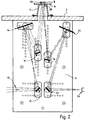
- Figure 2 shows the optical arrangement mounted on a baseplate 3 which may be slideably inserted into and removed from the spectrometer.
- the relay has mirrors 12, 14, 16, 18, 20, 22 which are mounted on the baseplate 3.
- the mirrors are shown as being adjustable in position, but once the relay has been correctly set up, no further adjustment should be necessary, and in production versions of this relay, there may be no adjustment facilities.
- the mirrors, some of which are concave, are front-silvered, or may be metal mirrors, to give high optical reflectivity.
- the relay has a housing 2 which includes a conical projection 4 with an aperture 26 which is normally closed by a shutter 50.
- the housing has a platen 6 with an aperture 44, and, in one embodiment, location of the platen 6 over the conical projection 4 causes the shutter 50 to open to allow access to a sample 8 located over the platen 6.
- the position of the sample does not have to be exactly on the platen 6; a satisfactory specular reflectance spectrum can still be obtained, even if the sample is up to 40 mm away from its optimum position.
- the optical relay includes mirrors 12, 14, 16 which divert the beam from the beam path 10 to the surface of the sample 8. Specularly reflected light from the surface of the sample 8 is directed by mirrors 18, 20, 22 to the detector 24.
- the incident light path and the reflected light path are not symmetrical. In particular the mirrors 16 and 18 are not symmetrical.
- the angle between the incident and reflected beams is about 12 degrees, and the beams meet at the outer surface of the platen 6.
- the reflected beam will still be directed by the mirrors 18, 20, 22 to the detector 24 if the gap between the housing 2 and the surface of the sample 8 is changed a little, for example if the sample 8 had a curved rather than a planar surface.
- the relay is therefore relatively insensitive to sample shape or configuration, and the position of the sample relative to the optical elements of the relay can change through ⁇ 20mm from a central point without adversely affecting the spectrum received at the detector 24.
- the platen 6 has a sample landing surface 28, and an aperture 44.
- the platen is mounted on the housing 2 of the relay by means of legs 32, 36, 38, 42 which are extend through slots 34, 40.
- the relay has sample preparation means comprising a cutter housing 30 in which is rotatably mounted a cutter 60 on a shaft for cutting the sample 8.
- Brushes 62 are mounted on the same shaft as the cutter 60, and function to sweep swarf away from the sample.
- the cutter housing 30 may be connected to a vacuum line to remove the swarf as it is formed.
- the relay is fitted into the spectrometer so that part of the relay lies in the beam path 10, with the housing 2 abutting the housing of the spectrometer.
- the edges of the baseplate 3 may optionally be provided with rubber strips to help ensure a good seal with the walls of the spectrometer.
- a sample 8 of plastics material is held against the aperture 44 of the platen 6 when the platen 6 is in the first position.
- the platen 6 is then swung down into the second position, causing the cutter 60 to rotate and cut the sample 8 to reveal a clean surface.
- the platen 6 is then swung back into the first position, with the sample 8 in place.
- This movement may also trigger the spectrometer to take a reading of the infrared spectrum of the sample surface. Alternatively the user could trigger the reading manually.
- One possible shutter mechanism 50 is shown in more detail in Figure 4.
- the shutter 50 is urged anticlockwise as viewed, by a coil spring 56.
- a stop 60 limits the anticlockwise movement of the shutter 50 so that the shutter 50 normally overlies the aperture 26 of the conical projection 4.
- a lever 52 is connected to a fixed point 64 by a first rod 46 at one end, and to the shutter 50 by a second rod 54 at its other end.
- the lever 52 has a pivot 62 which is located between the points at which the rods 46, 54 are connected to the lever.
- a push-button 48 is axially movable in a wall of the conical projection 4, as best shown in Figure 5.
- the push-button 48 has a lower cam surface 48a which bears down on the lever 52.
- Pushing the push-button 48 causes the lever 52 to turn about the pivot 62, and the rod 54 pushes the shutter 50 towards the position shown in broken lines, thereby opening the aperture 26.
- a second stop 58 limits the clockwise movement of the shutter 50.
- the push-button 48 may optionally be independently spring-loaded to facilitate the return action.
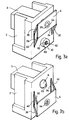
- the platen 6 bears down and presses on the push-button 48 when the platen 6 is correctly located in the first position shown in Figure 3a.
- the shutter 50 therefore only opens when a spectroscopic measurement is to be taken, reducing the chance of dust or other atmospheric contaminants entering the spectrometer via the aperture 26.
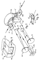
- Figures 6 and 7 show a dual-function optical relay 180, which has the facility to take both specular and diffuse reflectance spectra.
- specular reflectance spectra a solid sample will be placed at the end of a nose cone 104, in a manner as already described.
- diffuse reflectance spectrum a prepared sample will be introduced to the relay through an aperture 170.
- a lever 172 is used to switch the relay from specular to diffuse and vice versa .
- the lever 172 will move the orientation of mirrors within the cell to redirect the infrared beam.
- Figure 7 shows more detail of how this can be done.
- This Figure corresponds to Figure 2, and the mirrors 14,16,18 and 20 will be unchanged form that earlier embodiment.
- the mirrors 12 and 22 will however be movably mounted.
- the diffuse reflectance side of the relay has a sample support 174, a spherical mirror 176 and input and output mirrors 177 and 178.
- the mirrors 12 and 22 can be moved between a first position where they are part of the specular reflectance spectrum circuit and a second position where they are part of the diffuse reflectance circuit.
- Figure 7 shows in bold lines 10, the radiation path used for diffuse reflectance.
- the incoming radiation is reflected from mirror 12 (which is now in the position shown in bold lines) to mirror 178, to mirror 176, to the sample at 174, back to mirror 176, to mirror 177, to mirror 22 and from there to the spectrometer detector.
- This produces a diffuse reflectance spectrum, in a known way, and the set up is similar to that used for standard Diffuse Refelctance cells.
- the sample can be prepared on a piece of silicon carbide paper. It may be possible for the sample to be attached to a rod or other movable support which is then introduced from outside into the relay, to reach a fixed position (it is important for diffuse reflectance readings that the sample be accurately positioned).
- the mirrors 12 and 22 are moved into the positions indicated by dotted lines at 12' and 22'.
- the incoming radiation then is reflected along the path shown by dotted lines 10'.
- the movement of the mirrors 12 and 22 can be a simple swivel movement about a single axis, through an angle of about 90°. This is shown in Figure 7a.
- the relay 280 is bodily movable about a horizontal axis between the positions shown in the two Figures.
- a lever 272 is provided to initiate this movement and to ensure the correct final positioning of the housing.
- the relay In the Figure 8 position, the relay is set for specular reflectance measurements, and the arrangement will be as described with reference to the earlier Figures.
- the relay has been swung into a position where a radiation entry window 211 of a diffuse cell housing 213 is aligned with the infrared beam path 210 through the spectrometer.
- the housing 213 has a sample receiving aperture at 215.
- the housing swings on a pivot axis at 217, as indicated by an arrow 219.
- the infra red light will pass through either the specular reflectance circuit (in the position of Figure 8), or through the diffuse reflectance circuit (in the position of Figure 9) before passing to the detector of the spectrometer.
- the invention therefore provides a convenient optical relay for use with a standard spectrometer for measuring the spectra of plastics articles, whatever the shape of the article and with a minimum of pre-treatment.
Landscapes
- Physics & Mathematics (AREA)
- Spectroscopy & Molecular Physics (AREA)
- General Physics & Mathematics (AREA)
- Investigating Or Analysing Materials By Optical Means (AREA)
- Spectrometry And Color Measurement (AREA)
- Aiming, Guidance, Guns With A Light Source, Armor, Camouflage, And Targets (AREA)
- Optical Radar Systems And Details Thereof (AREA)
- Cameras In General (AREA)
- Glass Compositions (AREA)
- Optical Communication System (AREA)
Priority Applications (1)
| Application Number | Priority Date | Filing Date | Title |
|---|---|---|---|
| EP00109941A EP1026486B1 (fr) | 1994-11-17 | 1995-11-06 | Système de reproduction optique |
Applications Claiming Priority (2)
| Application Number | Priority Date | Filing Date | Title |
|---|---|---|---|
| GB9423186A GB2295244A (en) | 1994-11-17 | 1994-11-17 | Optical relay having at least two mirrors for a spectrometer |
| GB9423186 | 1994-11-17 |
Related Child Applications (2)
| Application Number | Title | Priority Date | Filing Date |
|---|---|---|---|
| EP00109941A Division EP1026486B1 (fr) | 1994-11-17 | 1995-11-06 | Système de reproduction optique |
| EP00109941.5 Division-Into | 2000-05-11 |
Publications (3)
| Publication Number | Publication Date |
|---|---|
| EP0713082A2 true EP0713082A2 (fr) | 1996-05-22 |
| EP0713082A3 EP0713082A3 (fr) | 1997-05-28 |
| EP0713082B1 EP0713082B1 (fr) | 2002-01-02 |
Family
ID=10764538
Family Applications (2)
| Application Number | Title | Priority Date | Filing Date |
|---|---|---|---|
| EP00109941A Expired - Lifetime EP1026486B1 (fr) | 1994-11-17 | 1995-11-06 | Système de reproduction optique |
| EP95307913A Expired - Lifetime EP0713082B1 (fr) | 1994-11-17 | 1995-11-06 | Module optique pour un spectromètre |
Family Applications Before (1)
| Application Number | Title | Priority Date | Filing Date |
|---|---|---|---|
| EP00109941A Expired - Lifetime EP1026486B1 (fr) | 1994-11-17 | 1995-11-06 | Système de reproduction optique |
Country Status (5)
| Country | Link |
|---|---|
| EP (2) | EP1026486B1 (fr) |
| AT (2) | ATE211544T1 (fr) |
| DE (2) | DE69527860T2 (fr) |
| ES (1) | ES2178622T3 (fr) |
| GB (1) | GB2295244A (fr) |
Cited By (1)
| Publication number | Priority date | Publication date | Assignee | Title |
|---|---|---|---|---|
| EP1557652A1 (fr) * | 2004-01-20 | 2005-07-27 | PerkinElmer Ltd. | Dispositif de mesure de la réflexion spéculaire d'un échantillon |
Families Citing this family (3)
| Publication number | Priority date | Publication date | Assignee | Title |
|---|---|---|---|---|
| GB0322043D0 (en) | 2003-09-20 | 2003-10-22 | Qinetiq Ltd | Apparatus for,and method of,classifying objects in waste stream |
| US7342657B2 (en) | 2004-11-03 | 2008-03-11 | Gretagmacbeth, Llc | Dual illumination angle goniometric spectrophotometer |
| DE102005016896B3 (de) | 2005-04-12 | 2006-10-26 | Sitronic Gesellschaft für elektrotechnische Ausrüstung mbH. & Co. KG | Sensoranordnung zur Temperaturmessung |
Family Cites Families (9)
| Publication number | Priority date | Publication date | Assignee | Title |
|---|---|---|---|---|
| US4473295A (en) * | 1981-08-31 | 1984-09-25 | Laser Precision Corporation | Parabolic focusing apparatus for optical spectroscopy |
| US4657390A (en) * | 1985-02-21 | 1987-04-14 | Laser Precision Corporation | Universal spectrometer system having modular sampling chamber |
| US4784488A (en) * | 1986-08-27 | 1988-11-15 | Laser Precision Corporation | Modular radiation transmission apparatus for spectrometers |
| US5075551A (en) * | 1990-03-12 | 1991-12-24 | Fuji Electric Co., Ltd. | Infrared absorption enhanced spectroscopic apparatus |
| US5048970A (en) * | 1990-06-29 | 1991-09-17 | Nicolas J. Harrick | Optical attachment for variable angle reflection spectroscopy |
| US5106196A (en) * | 1990-08-21 | 1992-04-21 | Brierley Philip R | Single adjustment specular reflection accessory for spectroscopy |
| FR2681941B1 (fr) * | 1991-10-01 | 1994-07-29 | Dilor | Dispositif de spectrometrie dispersive a filtrage de bande spectrale. |
| US5262845A (en) * | 1992-06-08 | 1993-11-16 | Harrick Scientific Corporation | Optical accessory for variable angle reflection spectroscopy |
| GB2288461A (en) * | 1994-04-07 | 1995-10-18 | Ford Motor Co | System for plastics identification |
-
1994
- 1994-11-17 GB GB9423186A patent/GB2295244A/en not_active Withdrawn
-
1995
- 1995-11-06 DE DE69527860T patent/DE69527860T2/de not_active Expired - Lifetime
- 1995-11-06 AT AT95307913T patent/ATE211544T1/de not_active IP Right Cessation
- 1995-11-06 ES ES00109941T patent/ES2178622T3/es not_active Expired - Lifetime
- 1995-11-06 EP EP00109941A patent/EP1026486B1/fr not_active Expired - Lifetime
- 1995-11-06 EP EP95307913A patent/EP0713082B1/fr not_active Expired - Lifetime
- 1995-11-06 AT AT00109941T patent/ATE222651T1/de not_active IP Right Cessation
- 1995-11-06 DE DE69524849T patent/DE69524849T2/de not_active Expired - Lifetime
Cited By (5)
| Publication number | Priority date | Publication date | Assignee | Title |
|---|---|---|---|---|
| EP1557652A1 (fr) * | 2004-01-20 | 2005-07-27 | PerkinElmer Ltd. | Dispositif de mesure de la réflexion spéculaire d'un échantillon |
| EP1939595A2 (fr) | 2004-01-20 | 2008-07-02 | PerkinElmer Ltd. | Mesure du facteur de réflexion d'un échantillon |
| EP1939595A3 (fr) * | 2004-01-20 | 2009-05-06 | PerkinElmer Ltd. | Mesure de la réflexion spéculaire d'un échantillon |
| US7595884B2 (en) | 2004-01-20 | 2009-09-29 | Perkinelmer Las, Inc. | Measurement of sample reflectance |
| US8345235B2 (en) | 2004-01-20 | 2013-01-01 | Perkinelmer Health Sciences, Inc. | Measurement of sample reflectance |
Also Published As
| Publication number | Publication date |
|---|---|
| DE69524849T2 (de) | 2002-09-19 |
| ATE211544T1 (de) | 2002-01-15 |
| EP0713082B1 (fr) | 2002-01-02 |
| EP0713082A3 (fr) | 1997-05-28 |
| ES2178622T3 (es) | 2003-01-01 |
| DE69527860D1 (de) | 2002-09-26 |
| EP1026486A2 (fr) | 2000-08-09 |
| DE69524849D1 (de) | 2002-02-07 |
| EP1026486A3 (fr) | 2000-08-23 |
| GB9423186D0 (en) | 1995-01-04 |
| GB2295244A (en) | 1996-05-22 |
| EP1026486B1 (fr) | 2002-08-21 |
| ATE222651T1 (de) | 2002-09-15 |
| DE69527860T2 (de) | 2002-12-05 |
Similar Documents
| Publication | Publication Date | Title |
|---|---|---|
| CN204405185U (zh) | 手持式分析器 | |
| US6819423B2 (en) | High spatial resolution infrared ellipsometer | |
| US5048970A (en) | Optical attachment for variable angle reflection spectroscopy | |
| US7477376B2 (en) | Self-calibrating optical reflectance probe system | |
| US20010035957A1 (en) | Multifunctional fourier transform infrared spectrometer system | |
| EP0713082B1 (fr) | Module optique pour un spectromètre | |
| US7265844B2 (en) | Horizontal surface plasmon resonance instrument with improved light path | |
| US10054484B2 (en) | Measuring arrangement for reflection measurement | |
| US4972092A (en) | Apparatus for determining the effective surface roughness of polished optical samples by measuring the integral scattered radiation | |
| US5262845A (en) | Optical accessory for variable angle reflection spectroscopy | |
| US5214286A (en) | Horizontal multiple internal reflection accessory for internal reflection spectroscopy | |
| WO1995032415A1 (fr) | Element de reflexion interne destine a l'examen de traces d'un materiau a l'aide de la spectroscopie infrarouge | |
| US5818046A (en) | Mid-infrared analysis system | |
| JP4119207B2 (ja) | 全反射プリズム及びそれを用いた全反射装置 | |
| US4303859A (en) | Infra-red analysis apparatus and method | |
| US20020089667A1 (en) | Spectrometer with automatic referencing | |
| EP1063501B1 (fr) | Tête de mesure pour instrument de mesure optique | |
| EP1939595B1 (fr) | Mesure de la réflexion spéculaire d'un échantillon | |
| JP2003215030A (ja) | 自動基準装置を備えた分光計 | |
| JPH1144636A (ja) | 全反射吸収スペクトル装置 | |
| van Nijnatten et al. | Spectrophotometer accessories for thin film characterisation | |
| CN111750787A (zh) | 一种用于玻璃量测的光谱测量仪 | |
| Frank et al. | Improved Fiber–Detector Coupling for MIR Spectroscopy Employing Shaped Silver Halide Fibers | |
| EP1358470A1 (fr) | Procede et appareil permettant de fournir un eclairage et d'en recueillir le rayonnement | |
| JPH06258217A (ja) | 試料採取装置 |
Legal Events
| Date | Code | Title | Description |
|---|---|---|---|
| PUAI | Public reference made under article 153(3) epc to a published international application that has entered the european phase |
Free format text: ORIGINAL CODE: 0009012 |
|
| AK | Designated contracting states |
Kind code of ref document: A2 Designated state(s): AT DE ES FR GB IT SE |
|
| PUAL | Search report despatched |
Free format text: ORIGINAL CODE: 0009013 |
|
| AK | Designated contracting states |
Kind code of ref document: A3 Designated state(s): AT DE ES FR GB IT SE |
|
| 17P | Request for examination filed |
Effective date: 19971020 |
|
| 17Q | First examination report despatched |
Effective date: 19990625 |
|
| GRAG | Despatch of communication of intention to grant |
Free format text: ORIGINAL CODE: EPIDOS AGRA |
|
| GRAG | Despatch of communication of intention to grant |
Free format text: ORIGINAL CODE: EPIDOS AGRA |
|
| GRAH | Despatch of communication of intention to grant a patent |
Free format text: ORIGINAL CODE: EPIDOS IGRA |
|
| GRAH | Despatch of communication of intention to grant a patent |
Free format text: ORIGINAL CODE: EPIDOS IGRA |
|
| GRAA | (expected) grant |
Free format text: ORIGINAL CODE: 0009210 |
|
| REG | Reference to a national code |
Ref country code: GB Ref legal event code: IF02 |
|
| AK | Designated contracting states |
Kind code of ref document: B1 Designated state(s): AT DE ES FR GB IT SE |
|
| PG25 | Lapsed in a contracting state [announced via postgrant information from national office to epo] |
Ref country code: IT Free format text: LAPSE BECAUSE OF FAILURE TO SUBMIT A TRANSLATION OF THE DESCRIPTION OR TO PAY THE FEE WITHIN THE PRESCRIBED TIME-LIMIT;WARNING: LAPSES OF ITALIAN PATENTS WITH EFFECTIVE DATE BEFORE 2007 MAY HAVE OCCURRED AT ANY TIME BEFORE 2007. THE CORRECT EFFECTIVE DATE MAY BE DIFFERENT FROM THE ONE RECORDED. Effective date: 20020102 Ref country code: AT Free format text: LAPSE BECAUSE OF FAILURE TO SUBMIT A TRANSLATION OF THE DESCRIPTION OR TO PAY THE FEE WITHIN THE PRESCRIBED TIME-LIMIT Effective date: 20020102 |
|
| REF | Corresponds to: |
Ref document number: 211544 Country of ref document: AT Date of ref document: 20020115 Kind code of ref document: T |
|
| REF | Corresponds to: |
Ref document number: 69524849 Country of ref document: DE Date of ref document: 20020207 |
|
| PG25 | Lapsed in a contracting state [announced via postgrant information from national office to epo] |
Ref country code: SE Free format text: LAPSE BECAUSE OF FAILURE TO SUBMIT A TRANSLATION OF THE DESCRIPTION OR TO PAY THE FEE WITHIN THE PRESCRIBED TIME-LIMIT Effective date: 20020402 |
|
| ET | Fr: translation filed | ||
| PG25 | Lapsed in a contracting state [announced via postgrant information from national office to epo] |
Ref country code: ES Free format text: LAPSE BECAUSE OF FAILURE TO SUBMIT A TRANSLATION OF THE DESCRIPTION OR TO PAY THE FEE WITHIN THE PRESCRIBED TIME-LIMIT Effective date: 20020730 |
|
| PLBE | No opposition filed within time limit |
Free format text: ORIGINAL CODE: 0009261 |
|
| STAA | Information on the status of an ep patent application or granted ep patent |
Free format text: STATUS: NO OPPOSITION FILED WITHIN TIME LIMIT |
|
| 26N | No opposition filed | ||
| REG | Reference to a national code |
Ref country code: FR Ref legal event code: TP |
|
| REG | Reference to a national code |
Ref country code: FR Ref legal event code: CD Ref country code: FR Ref legal event code: CA |
|
| PGFP | Annual fee paid to national office [announced via postgrant information from national office to epo] |
Ref country code: FR Payment date: 20081106 Year of fee payment: 14 |
|
| REG | Reference to a national code |
Ref country code: FR Ref legal event code: ST Effective date: 20100730 |
|
| PG25 | Lapsed in a contracting state [announced via postgrant information from national office to epo] |
Ref country code: FR Free format text: LAPSE BECAUSE OF NON-PAYMENT OF DUE FEES Effective date: 20091130 |
|
| PGFP | Annual fee paid to national office [announced via postgrant information from national office to epo] |
Ref country code: DE Payment date: 20141201 Year of fee payment: 20 Ref country code: GB Payment date: 20141027 Year of fee payment: 20 |
|
| REG | Reference to a national code |
Ref country code: DE Ref legal event code: R071 Ref document number: 69524849 Country of ref document: DE |
|
| REG | Reference to a national code |
Ref country code: GB Ref legal event code: PE20 Expiry date: 20151105 |
|
| PG25 | Lapsed in a contracting state [announced via postgrant information from national office to epo] |
Ref country code: GB Free format text: LAPSE BECAUSE OF EXPIRATION OF PROTECTION Effective date: 20151105 |