EP0713212A2 - Appareil d'enregistrement et de reproduction optique d'information - Google Patents
Appareil d'enregistrement et de reproduction optique d'information Download PDFInfo
- Publication number
- EP0713212A2 EP0713212A2 EP95308123A EP95308123A EP0713212A2 EP 0713212 A2 EP0713212 A2 EP 0713212A2 EP 95308123 A EP95308123 A EP 95308123A EP 95308123 A EP95308123 A EP 95308123A EP 0713212 A2 EP0713212 A2 EP 0713212A2
- Authority
- EP
- European Patent Office
- Prior art keywords
- light beam
- light
- converged
- recording medium
- objective
- Prior art date
- Legal status (The legal status is an assumption and is not a legal conclusion. Google has not performed a legal analysis and makes no representation as to the accuracy of the status listed.)
- Withdrawn
Links
- 230000003287 optical effect Effects 0.000 title claims abstract description 131
- 230000010287 polarization Effects 0.000 claims abstract description 104
- 238000001514 detection method Methods 0.000 claims abstract description 28
- 239000000463 material Substances 0.000 claims description 24
- 238000005520 cutting process Methods 0.000 claims description 5
- 238000003384 imaging method Methods 0.000 abstract description 16
- 238000002834 transmittance Methods 0.000 description 27
- VYPSYNLAJGMNEJ-UHFFFAOYSA-N Silicium dioxide Chemical compound O=[Si]=O VYPSYNLAJGMNEJ-UHFFFAOYSA-N 0.000 description 20
- 230000005540 biological transmission Effects 0.000 description 18
- GWEVSGVZZGPLCZ-UHFFFAOYSA-N Titan oxide Chemical compound O=[Ti]=O GWEVSGVZZGPLCZ-UHFFFAOYSA-N 0.000 description 16
- 230000004075 alteration Effects 0.000 description 15
- 230000008859 change Effects 0.000 description 10
- 239000004065 semiconductor Substances 0.000 description 10
- 235000012239 silicon dioxide Nutrition 0.000 description 10
- 239000000377 silicon dioxide Substances 0.000 description 10
- 238000009826 distribution Methods 0.000 description 9
- 238000010586 diagram Methods 0.000 description 7
- 239000011521 glass Substances 0.000 description 7
- 239000004408 titanium dioxide Substances 0.000 description 7
- 230000000694 effects Effects 0.000 description 3
- 238000004519 manufacturing process Methods 0.000 description 3
- 238000000034 method Methods 0.000 description 3
- 230000002093 peripheral effect Effects 0.000 description 3
- 230000009467 reduction Effects 0.000 description 3
- 230000035945 sensitivity Effects 0.000 description 3
- 206010010071 Coma Diseases 0.000 description 2
- MCMNRKCIXSYSNV-UHFFFAOYSA-N Zirconium dioxide Chemical compound O=[Zr]=O MCMNRKCIXSYSNV-UHFFFAOYSA-N 0.000 description 2
- 238000003475 lamination Methods 0.000 description 2
- 238000012986 modification Methods 0.000 description 2
- 230000004048 modification Effects 0.000 description 2
- 241001519451 Abramis brama Species 0.000 description 1
- 150000001875 compounds Chemical class 0.000 description 1
- 230000006872 improvement Effects 0.000 description 1
- 229910001635 magnesium fluoride Inorganic materials 0.000 description 1
- 238000005259 measurement Methods 0.000 description 1
- 239000007787 solid Substances 0.000 description 1
Images








Classifications
-
- G—PHYSICS
- G11—INFORMATION STORAGE
- G11B—INFORMATION STORAGE BASED ON RELATIVE MOVEMENT BETWEEN RECORD CARRIER AND TRANSDUCER
- G11B7/00—Recording or reproducing by optical means, e.g. recording using a thermal beam of optical radiation by modifying optical properties or the physical structure, reproducing using an optical beam at lower power by sensing optical properties; Record carriers therefor
- G11B7/12—Heads, e.g. forming of the optical beam spot or modulation of the optical beam
- G11B7/135—Means for guiding the beam from the source to the record carrier or from the record carrier to the detector
- G11B7/1356—Double or multiple prisms, i.e. having two or more prisms in cooperation
-
- G—PHYSICS
- G11—INFORMATION STORAGE
- G11B—INFORMATION STORAGE BASED ON RELATIVE MOVEMENT BETWEEN RECORD CARRIER AND TRANSDUCER
- G11B11/00—Recording on or reproducing from the same record carrier wherein for these two operations the methods are covered by different main groups of groups G11B3/00 - G11B7/00 or by different subgroups of group G11B9/00; Record carriers therefor
- G11B11/10—Recording on or reproducing from the same record carrier wherein for these two operations the methods are covered by different main groups of groups G11B3/00 - G11B7/00 or by different subgroups of group G11B9/00; Record carriers therefor using recording by magnetic means or other means for magnetisation or demagnetisation of a record carrier, e.g. light induced spin magnetisation; Demagnetisation by thermal or stress means in the presence or not of an orienting magnetic field
- G11B11/105—Recording on or reproducing from the same record carrier wherein for these two operations the methods are covered by different main groups of groups G11B3/00 - G11B7/00 or by different subgroups of group G11B9/00; Record carriers therefor using recording by magnetic means or other means for magnetisation or demagnetisation of a record carrier, e.g. light induced spin magnetisation; Demagnetisation by thermal or stress means in the presence or not of an orienting magnetic field using a beam of light or a magnetic field for recording by change of magnetisation and a beam of light for reproducing, i.e. magneto-optical, e.g. light-induced thermomagnetic recording, spin magnetisation recording, Kerr or Faraday effect reproducing
- G11B11/10532—Heads
- G11B11/10541—Heads for reproducing
- G11B11/10543—Heads for reproducing using optical beam of radiation
Definitions
- the present invention relates to an optical information recording and reproducing apparatus for recording information on an optical recording medium or reproducing information from the medium and, more particularly, to an opto-magnetic recording and reproducing apparatus using an opto-magnetic recording medium such as an opto-magnetic disk.
- an optical head for an optical information recording and reproducing apparatus using an opto-magnetic system is ordinarily arranged in such a manner that a light beam from a light source travels to a recording medium via a polarization beam splitter and, and a part of the light beam reflected by the medium diverges to travel to a photo-detector when the reflected light beam again passes through the polarization beam splitter.
- the polarization beam splitter it is necessary for the polarization beam splitter to lead a maxim quantity of light to the medium in a forward optical path and to provide a maximum amount of a Kerr component in the divergent beam to the detector in a backward optical path.
- the polarization beam splitter is disposed in a parallel beam.
- the polarized light separating film of the polarization beam splitter ordinarily has an incident angle dependency in its characteristics. That is, the polarized light transmittance and reflectance and phase differences produced between polarized light components vary with respect to the angle of incidence of the light beam upon the polarized light separating film. There is a need to uniformize these characteristics in a cross section of the beam. Then, a need for disposing the polarization beam splitter in a parallel beam arises.
- an optical system must be formed in which a divergent beam from the light source is temporarily formed into a parallel beam by a collimator lens, and in which the parallel beam is thereafter converged on the recording medium by an objective.
- These two lenses i.e., the objective and collimator lenses of the optical system, are indispensable if they are used to form an infinite imaging system.
- an optical magnetic head as small as optical heads of compact disk players in the number of parts and in size can be arranged by removing the collimator lens and by forming an finite imaging system by the objective lens. Also in such a case, there is a possibility that a light and high-speed apparatus will be realized which uses a very small optical system further miniaturized.
- the objective and collimator lenses can be brought close to each other and the collimator lens can also serve as a lens for converging the detected beam split by the polarization beam splitter, which is necessary in the conventional art.
- the collimator lens can also serve as a lens for converging the detected beam split by the polarization beam splitter, which is necessary in the conventional art.
- means for miniaturization are increased if it is not necessary to place the polarization beam splitter in a parallel beam.
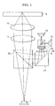
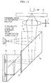
- Fig. 1 shows a system disclosed in Japanese Patent Laid-Open Publication No. 234173/1993 as an example of an invention provided from such a view point.
- a divergent light beam from a semiconductor laser device 1 passes through a polarization beam splitter 26 and is them changed into a parallel beam by a collimator lens 14.
- This parallel beam is converged on an opto-magnetic disk 6 by an objective 15.
- a detected light beam is reflected by the disk, passes through the objective and the collimator lens, and is reflected by the polarization beam splitter 26, thereby being deflected in a direction different from that of the light source.
- the detected light beam is again reflected by the next reflecting means 27 to reach photo-detectors 10 for opto-magnetic detection and servo detection by traveling through a 1/2 wavelength plate 8, a cylindrical lens 28 and a beam splitter 29.
- the beam splitter 26 and the reflecting means 27 have films having substantially the same characteristics.
- the detected light beam is reflected by the beam splitter 26 to have a phase difference and is then reflected by the reflecting means 27 having the same characteristics so that the incident angles of rays incident upon the reflecting means 27 are in an inverted relationship with the incident angles of rays incident upon the beam splitter 26, thereby canceling the phase difference.
- the reflecting means 27 having substantially the same characteristics as the polarization beam splitter 26 is placed in the optical path of the detected light beam reflected by the polarization beam splitter 26 to cancel the phase differences of p- and s-polarized light created in the detected light beam.
- a phase difference created in a transmitted or reflected light beam by a polarization beam splitter has an incident angle dependency due to the fact that the polarized light separating film is ordinarily a laminated film of a dielectric having characteristics determined according to the relationship between the refractive indexes, the thicknesses of layers of the film and the wavelength of the incident light beam.
- each layer of the dielectric multilayer film is formed so as to satisfy the condition that its thickness is uniform within the range of manufacturing error in an effective diametrical area.
- the film designed to realize a certain characteristic is formed, to put it simply, by setting its thickness to the desired value with respect to the ray traveling at the refractive angle ⁇ , i.e., a value obtained by multiplying the desired distance for the ray by cos ⁇ .
- the incident light beam has an incident angle constant in the entire beam area (that is, in the case of a parallel beam)
- a phase difference is created uniformly through the light beam area.
- the effective film thickness is changed according to the incident angle of the ray.
- the overall characteristics of the polarized light separating film differ from the desired characteristics.
- the divergent light beam in the forward optical path from the light source to the medium via the polarization beam splitter also undergoes phase modulation of the film of the polarization beam splitter.
- the light source is a semiconductor laser device
- the light beam in the forward optical path has only a linearly-polarized component
- the polarization beam splitter receives only a p-polarized component.
- the phase modulation effect on rays depends on the incident angle and is not uniform in a cross section of the light beam. Even if the light beam has only a p-polarized component, it has local phase advancement and lag according to the incident angle. That is, such phase modulation causes a wavefront aberration of the light beam in the forward path.
- phase difference can be allowed as a reflection phase difference of the detected light beam reflected by the polarization beam splitter, it is necessary to reduce the incident angle dependency of phase variation with respect to the p-polarized component of the transmitted light beam passing through the polarization beam splitter.
- the first problem to be solved by the present invention is summarized below. While importance has been set on canceling or reducing a phase difference created in the detected light beam, it is necessary to recognize the influence of the phase characteristics of the film upon the light beam in the forward path causing a wavefront aberration. To reduce this aberration, it is necessary to reduce the incident angle dependency of the phase through the film in the forward optical path.
- the transmittance and reflectance also have incident angle dependencies for the same reason as in the above, and these dependencies must be considered.
- the specification of the conventional art includes a description of the effect that, if the beam splitter is designed to reduce the phase difference, the transmittance and reflectance characteristics change so that the utilization efficiency is reduced, but it includes no description of the incident angle dependency of the transmittance and reflectance.
- the film of the polarization beam splitter is simply designed to set the desired transmittance and reflectance with respect to a principal ray without particularly considering the incident angle dependency, then certain distributions of the transmittance and reflectance occur in a direction along the incidence surface of the polarization beam splitter film.
- the transmittance and reflectance are non-uniform from a point at which a marginal ray is incident at an angle of 45 ° + ⁇ to an opposite point of an incident angle of 45 ° - ⁇ , and may have asymmetric distributions such as those shown in Fig. 2.
- the quantity of light incident upon the objective in the forward optical path has an asymmetric distribution about the optical axis, so that the light spot on the medium is also asymmetric.
- the transmittance has a distribution such as to be lower with respect to marginal rays at opposite points of 45 ° ⁇ ⁇ .
- the diameter of a substantial area of the light beam in the corresponding cross section is smaller, that is, the effective numerical aperture (NA). is smaller and the light spot is larger.
- the light spot on the recording medium is influenced to cause a hindrance to recording and reproduction. Therefore, it is particularly important to maintain certain degrees of symmetry and uniformity of the quantity of light in the forward optical path.
- the film is designed so that the transmittance of the p-polarized component is uniform at intermediate value of about 85 % without an angle dependency, the problem of an increase in the total number of film layers and other problems are encountered.
- a loss in the quantity of light is also caused by the influence of an asymmetry of the reflectance due to an incident angle dependency when the detected light beam reflected by the recording medium and returned to the polarization beam splitter is reflected by the polarization beam splitter, although this influence is not as serious as that of the forward optical path.
- the second problem to be solved by the present invention is summarized below. It is necessary to recognize that the angle dependency of the polarized light separating transmission and reflection characteristics of the polarization beam splitter largely affects the shape of the detection spot on the recording medium and the loss in the quantity of light of the detected light beam and, therefore, to limit the incident angle dependency of the polarized light separating transmission and reflection characteristics of the film.
- the absolute value of the quantity of light reaching the detectors 10 is not large enough to ensure the desired detection performance against noise. Only 2.25 % of the p-polarized component of the detected light beam can reach the detectors 10.
- the reflecting means 27 must be backed by the same film-sandwiching as that for the beam splitter 26.
- the third problem to be solved by the present invention is summarized below.
- unnecessary transmission occurs due to the polarized light separating transmission and reflection characteristics of the reflecting means 27 to influence the loss in the quantity of light of the detected light beam. It is necessary to recognize that the angle dependency of the polarized light separating transmission and reflection characteristics of the reflecting means 27 also influences the loss in the quantity of peripheral light. To reduce this influence, it is necessary to optimize the polarized light separating transmission and reflection characteristics of the film and the incident angle dependency of the same. Further, to form the reflecting means 27 so that its characteristics are equal to those of the polarization beam splitter 26, additional manufacturing steps for providing a film-sandwiching glass part and attaching the glass part to the back surface of the film are required.
- the present invention aims to realize further stabilized characteristics of a finite imaging system in an optical head used in an opto-magnetic recording and reproducing apparatus.
- an object of the present invention is to provide an optical information recording and reproducing apparatus in which transmission and reflection characteristics are uniform through the entire effective diametrical area of a light beam in a forward optical path, and in which a serious influence upon the shape of a spot on a recording medium can be prevented.
- Another object of the present invention is to provide an optical information recording and reproducing apparatus in which substantially no aberration occurs in a light beam in a forward optical path due to characteristics of films.
- Yet another object of the present invention is to provide an optical information recording and reproducing apparatus in which a large quantity of light reaching a detector can be maintained through the entire effective diametrical area of a detected light beam, whereby the influence of noise can be reduced.
- Still another object of the present invention is to provide an optical information recording and reproducing apparatus in which a phase compensating surface is provided as a back reflecting surface, which can be formed only by attaching a film without a glass backing.
- a further object of the present invention is to provide an optical information recording and reproducing apparatus in which the influence of a phase difference can be eliminated by cutting the phase difference without compensating the same, and in which a cross-talk form adjacent tracks can be simultaneously eliminated.
- a further object of the present invention is to provide an optical information recording and reproducing apparatus which can be arranged to reduce the track pitch of a recording disk as well as to improve the head optical system, and in which the tilt allowance range can be increased advantageously.
- an optical information recording and reproducing apparatus comprising a forward path optical system including a polarization beam splitter for reflecting a linearly-polarized light beam in the form of a divergent light beam from a light source for producing a light beam for recording or reproducing information, and an objective of a finite imaging system for converging the reflected light beam on an opto-magnetic recording medium, and a backward path optical system in which the reflected light beam from the recording medium is converged by the finite-imaging objective, and in which the converged light beam passes through the polarization beam splitter and is further reflected by a total reflection surface for reflecting this light beam to be led to detection means.
- a phase difference created in the convergent light beam when the light beam passes through a polarized light separating surface of the polarization beam splitter is compensated by the total reflection surface.
- the problem of a wavefront aberration caused in the light beam in the forward optical path when the light beam passes through the polarized light separating film and the problem of the angle dependency of the transmittance and reflectance characteristics of the polarized light separating film, that were difficult to solve in the conventional forward optical path arrangement shown in Fig. 2, can be solved by setting a forward reflecting path and a backward transmission path as optical paths through the polarization beam splitter while the number of film layers is limited.
- the above-mentioned total reflection surface is a back reflecting surface formed integrally with the polarization beam splitter by a dielectric multilayer film.
- the above-described means of the present invention uses a back reflecting film and is, therefore, essentially free from the problem of the angle dependency of the reflectance.
- a reflectance of approximately 100 % as a reflectance of total reflection can easily be achieved thereby, so that the loss in the quantity of light of the detected light beam can be limited to improve noise proofing.
- a design optimized for a desirable phase difference characteristic is possible while the number of film layers is limited. Further, there is no need for attaching a glass member to the back surface, so that the number of parts and the number of manufacturing steps can be reduced.
- a vitreous material forming the polarization beam splitter and the back reflecting surface has a refractive index of 1.7 or more at operating wavelengths.
- the inclination of rays in the glass can be reduced if the glass is selected from those having a high refractive index. Accordingly, it is possible to narrow the range in which the angle dependency of the film with respect to marginal rays must be considered. A burden on the film design can be reduced thereby.
- the object-side NA of the finite-imaging objective is 0.19 or less.
- the object-side NA determines the angular range of marginal rays, and the range in which the angle dependency of the film with respect to marginal rays must be considered can be reduced by limiting the angular range within predetermined limits, thereby reducing a burden on the film design.
- the present invention provides, as means for achieving the above-described objects, another optical information recording and reproducing apparatus comprising a forward path optical system including a polarization beam splitter for reflecting a linearly-polarized light beam in the form of a divergent light beam from a light source for producing a light beam for recording or reproducing information, a collimator lens for changing the reflected light beam into a parallel beam, and an objective for converging the parallel beam to irradiate an opto-magnetic recording medium, and a backward path optical system in which the reflected light beam from the opto-magnetic recording medium again passes the collimator lens to be changed into a convergent beam after passing through the objective, and this convergent light beam passes through the polarization beam splitter and is further reflected by a total reflection surface for reflecting this light beam to be led to detection means.
- a phase difference created in the convergent light beam when the light beam passes through a polarized light separating surface of the polarization beam splitter is compensate
- a parallel light beam is formed in the optical path between the collimator lens and the objective lens, so that the size of a fixed head unit can be reduced if a separated optical system arrangement, for example, is adopted.
- the present invention provides, as means for achieving the above-described objects, still another optical information recording and reproducing apparatus comprising a forward path optical system including a polarization beam splitter for reflecting a linearly-polarized light beam in the form of a divergent light beam from a light source for producing a light beam for recording or reproducing information, and an objective of a finite imaging system for converging the reflected divergent light beam on an opto-magnetic recording medium, and a backward path optical system in which the reflected light beam from the recording medium is converged by the finite-imaging objective, the converged light beam then passes through the polarization beam splitter, and rays in an end portion of the light source in a range of an effective light beam diameter are thereafter cut off by a light shield plate, the light beam thereafter being led to detection means.
- a forward path optical system including a polarization beam splitter for reflecting a linearly-polarized light beam in the form of a divergent light beam from a light source for producing a light
- rays in a portion of the light beam largely influenced by a phase difference created by the polarized light separating film of the polarization beam splitter are cut off to eliminate the influence of the phase difference.
- cross-talk components from tracks on the medium adjacent to a track presently tracked by the light beam can be eliminated.
- the present invention provides, as means for achieving the above-described objects, a further optical information recording and reproducing apparatus comprising a forward path optical system including a polarization beam splitter for reflecting a linearly-polarized light beam in the form of a divergent light beam from a light source for producing a light beam for recording or reproducing information, a collimator lens for changing the reflected light beam into a parallel beam, and an objective for converging the parallel beam on an opto-magnetic recording medium, and a backward path optical system in which the reflected light beam from the opto-magnetic recording medium again passes the collimator lens to be changed into a convergent beam after passing through the objective, the converged light beam then passes through the polarization beam splitter, and rays in an end portion of the light source in a range of an effective light beam diameter are thereafter cut off by a light shield plate, the light beam thereafter being led to detection means.
- a forward path optical system including a polarization beam splitter for reflecting a linear
- rays in a portion of the light beam largely influenced by a phase difference are cut off to eliminate the influence of the phase difference.
- cross-talk components from tracks on the medium adjacent to a track presently tracked by the light beam can be eliminated.
- the above-mentioned light shield plate cuts off opposite end portions of the converged light beam in the range of the effective light beam diameter corresponding to the direction of plane of incidence on the polarization beam splitter.
- the angle of incidence of marginal rays on the polarized light separating film of the polarization beam splitter is largely different from the incident angle of the principal ray in the direction along the above-mentioned plane of incidence. Accordingly, opposite end portions of the light beam in the direction along the plane of incidence on the polarized light separating film are influenced most greatly by the phase difference due to the change in incident angle. According to the above-described means of the present invention, therefore, these portions are cut off to effectively eliminate the influence of the phase difference.
- the above-mentioned light shield plate cuts off opposite end portions of the converged light beam in the range of the effective light beam diameter which are greatly influenced by a phase difference created by passage through the polarization beam splitter.
- the apparatus of the invention can reproduce a signal with improved reliability in comparison with the conventional apparatus not separating such light beam portions.
- the end portion of the light beam cut off by the light shield plate includes a portion facing in a direction toward a track on the optical recording medium which is adjacent to a track presently tracked by the light beam.
- Information written in a track adjacent to a track on the recording medium from which the necessary information is being presently read out can leak to a portion of the detected light beam acing the adjacent track. According to the above-described means of the present invention, such a portion of the light beam is cut off to effectively eliminate the influence of the adjacent track.
- the above-mentioned light shield plate cuts off opposite end portions of the converged light beam in the range of the effective light beam diameter which contain a large amount of cross-talk components from tracks on the optical recording medium adjacent to a track presently tracked by the light beam.
- the apparatus of the invention can reproduce a signal with improved reliability in comparison with the conventional apparatus not separating such light beam portions.
- the above-mentioned polarization beam splitter reflects linearly-polarized light from the light source by a substantially constant reflectance.
- the above-described means of the present invention prevents a reduction in the quantity of light in a peripheral portion of the forward path light beam incident on the objective due to passage through the polarized light separating film, and also prevent an asymmetric light quantity distribution with respect to the principal ray. It is therefore possible to form an ideal reproducing light spot on the recording medium without forming an excessively large spot or an asymmetric spot.
- the detected light beam from the recording medium can pass through the polarization beam splitter at a substantially uniform transmittance along any plane of polarization.
- the effective quantity of detected light can be fully utilized without wastefully cutting it.
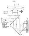
- a magnetic head 30 is provided to apply a magnetic field to an opto-magnetic recording medium 6.
- a lens 2 is a finite-imaging system objective which converges a divergent light beam from a semiconductor laser light source 1 directly on the opto-magnetic recording medium 6.
- the objective 2 has an object-side NA ⁇ 0.18 and an image-side NA ⁇ 0.55.
- a divergent light beam emitted from the semiconductor laser device 1 provided as a light source for producing a light beam for recording or reproducing information is reflected by a polarized light separating film 4 of a polarization beam splitter 3, thereby being deflected toward the objective 2.
- the direction of polarization of the light beam emitted from the light source is represented by lines 5, and the light beam has a polarized wave surface perpendicular to the plane of paper of Fig. 3.
- the light beam in this forward optical path is incident as an s-polarized component upon the polarization beam splitter 3.
- the polarized light separating film 4 Since the polarized light separating film 4 has an s-polarized component reflectance ⁇ 85 %, 85 % of the quantity of light of the light beam in the forward optical path is deflected toward the objective 2.
- a detected light beam converged on the opto-magnetic recording medium 6 and reflected by the same travels through the objective 2 and passes as a convergent light beam through the polarized light separating film 4 of the polarization beam splitter 3. This convergent light beam is again reflected by a back reflecting film 7 formed integrally with the polarization beam splitter 3. Thereafter, the detected light beam passes through a halfwave plate 8 and is split into beams to detectors 10 by a polarization beam splitter 9 for magnetic differential detection and automatic focusing beam-size detection.
- An opto-magnetic signal, an automatic focusing (AF) signal and an automatic tracking (AT) signal are detected from the light beam by a well-known method.
- the NA of the objective 2 on the light source side in the optical head optical system is small while the refractive index of the vitreous material is high.
- the NA of the objective 2 on the light source side is set to 0.19 or less and the refractive index of the vitreous material at operating wavelengths is set to 1.7 or more, thereby enabling the angle of incidence on the film to be limited within the range of about [the incident angle of the principal ray] ⁇ 6 °.
- the angle of marginal (peripheral) rays with respect to the principal ray is 10.4 °.
- a material having a refractive index of 1.79279 at operating wavelengths is selected as the vitreous material of the polarization beam splitter 3 to reduce the above-mentioned angle to 5.8 °. Therefore, the range of compensation of an angle dependency of the film is at most 45 ⁇ 6 °.
- the polarized light separating film 4 is a dielectric multilayer film formed of a lamination of six layers, i.e., three layers of silicon dioxide (SiO2) and three layers of titanium dioxide (TiO2) alternately superposed on the vitreous material.
- SiO2 silicon dioxide
- TiO2 titanium dioxide
- Each of the silicon dioxide layers has a thickness of 118.0 nm
- each of the titanium dioxide layers has a thickness of 306.8 nm.
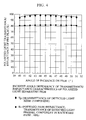
- the graph of Fig. 4 shows incident angle dependencies of the polarized light transmittance and reflectance of the first design example of the film.
- the ordinate represents the transmittance and reflectance of the polarized light separating film while the abscissa represents the angle of incidence on the polarized light separating film.
- the symbol ⁇ designates the transmittance Tp of p-polarized light
- the symbol ⁇ designates the reflectance Rs of s-polarized light.
- a flat characteristic is obtained in which Tp is higher than about 95 % and Rs is 82 ⁇ 2 % generally in the range of 45 ⁇ 6 °.
- the obtained characteristics are flat.
- Fig. 5 shows a change in phase, i.e., a wavefront aberration caused in the light beam after reflection by the polarization beam splitter 3 in the forward optical path.
- the ordinate represents the quantity in terms of wavefront aberration in a cross section along the plane of incidence, converted from a phase distribution of the s-polarized component formed at the time of reflection by the polarized light separating film 4.
- the symbol ⁇ designates the wavefront aberration.
- the peak-to-peak value of the wavefront aberration is about 0.1 ⁇ .
- a phase difference is created according to the incident angle.
- a Fresnel component corresponds to the s-polarized component while a Kerr component corresponds to the p-polarized component.
- the detected light beam transmitted through the polarization beam separating film 4 has a phase difference between the Fresnel component and the Kerr component.
- the phase difference varies with the incident angle.
- the graph of Fig. 6 shows an incident angle dependency of the phase of each polarized light component.
- the ordinate represents the phase of each polarized light component after transmission through the polarized light separating film 4 while the abscissa represents the angle of incidence on the polarized light separating film 4.
- the symbol ⁇ designates the phase of the p-polarized component, and the symbol ⁇ designates the phase of the s-polarized component.
- the detected light beam is reflected and deflected by the reflecting film 7 for phase difference compensation.
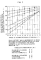
- the graph of Fig. 7 shows an incident angle dependency of the phase difference created by reflection on this compensating film 7.
- the ordinate represents the phase after reflection by the reflecting film 7 for phase difference compensation while the abscissa represents the angle of incidence on the reflecting film.
- Fig. 7 shows the results of measurement of three types of design examples A, B, and C.
- the pairs of symbols ⁇ and ⁇ , ⁇ and ⁇ , and ⁇ and ⁇ designate the types A, B, and C, respectively. Of these symbols, the solid ones designate the s-polarized component while the blank ones designate the p-polarized component.
- the compensating film 7 is formed as a total reflection film unlike the polarized light separating film 4 with respect to the transmittance and reflectance. With respect to the incident angle dependency, the compensating film is designed so as to satisfy the conditions described below by considering the characteristics of the polarized light separating film 4.
- a marginal ray incident at an angle of 45 + 6 ° on the polarized light separating film 4 is incident at an angle of 45 - 6 ° on the compensating film 7
- a marginal ray incident at an angle of 45 - 6 ° on the polarized light separating film 4 is incident at an angle of 45 + 6 ° on the compensating film 7. Therefore, the phase difference created by transmission through the polarized light separating film 4 is canceled at the time of reflection by the compensating film 7.
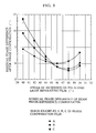
- Fig. 8 shows a residual phase difference uncanceled due to a small difference between the angle dependencies of the phase shown in Figs. 6 and 7. In the graph of Fig.
- the ordinate presents the residual phase difference after phase compensation while the abscissa represents the angle of incidence on the polarized light separating film.
- the symbols ⁇ , ⁇ , and ⁇ designate the types of phase difference compensating reflecting films A, B, and C, respectively.
- the reflecting film 7 can be designed with greater freedom by taking only the phase difference into consideration.
- the three design examples A, B, and C have therefore been shown.
- the film of each example can be formed so as to have a smaller number of layers, i.e., six layers in this embodiment.
- the reflecting film 7 is a dielectric multilayer film formed of a lamination of six layers, i.e., three layers of silicon dioxide (SiO2) and three layers of titanium dioxide (TiO2) alternately superposed.
- each silicon dioxide layer has a thickness of 70.0 nm while each titanium dioxide layer has a thickness of 140.5 nm.
- each silicon dioxide layer has a thickness of 90.0 nm while each titanium dioxide layer has a thickness of 132.5 nm.
- each silicon dioxide layer has a thickness of 110.0 nm while each titanium dioxide layer has a thickness of 124.5 nm.
- compensating reflecting films having intermediate characteristics between those of the types A to C can be formed by setting the film thickness ratio to intermediate values between the ratios of the above-mentioned values.
- the objective 2 forms a finite imaging system and only one objective 2 may be driven for AF and AT servo operations.
- Arrows 11 in Fig. 3 designate the directions in which the objective 2 can be moved.
- the direction across the tracks of the opto-magnetic recording medium 6 is parallel to the plane of paper of Fig. 3.
- the phase difference between the p- and s-polarized light components created in the detected light beam is compensated buy the above-described arrangement.
- the detected light beam then passes the halfwave plate 8 disposed in the optical path and is split into two beams for opto-magnetic signal differential detection by the polarization beam splitter 9, as mentioned above. Also, servo signals for opto-magnetic signal detection are simultaneously separated and detected from the light beam.
- marginal rays in Fig. 3 have angles of 0 ° and 180 ° as azimuths of the light beam, as shown in Fig. 9, marginal rays in the direction perpendicular to the plane of paper of Fig. 3 correspond to azimuths of 90 ° and 270 °.
- a polarization beam splitter may be arranged to form an optical head by effecting reflection in a forward optical path and transmission in a backward optical path in order to eliminate the influence of the polarized light separating film as a wavefront aberration on the light beam in the forward optical path, i.e., the incident angle dependency of phase modulation of polarized components of the light in the forward optical path as well as to limit the wavelength dependency of the transmittance and reflectance of the separating film and to eliminate the incident angle dependency to obtain a flat characteristic.
- the angle of incidence on the film may be limited within the range of about [the incident angle of the principal ray] ⁇ 6 ° by setting the object-side NA of the objective to 0.19 or less and the refractive index at operating wavelengths to 1.7 or more. It is possible to reduce the burden on the film design by selecting these values.
- the vitreous material of the polarization beam splitter is G
- the refractive index of this material is ng
- a material having a relatively-high refractive index is H
- a material having a low refractive index is L
- the refractive indexes of these materials are nh and nl.
- the air-equivalent thickness of H is dh
- the air-equivalent thickness of L is dl (each value defined with respect to d-line wavelength).
- the structure of the polarized light separating film is a four-layer structure of G/H/L/H/L in the direction of traveling of light in which
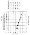
- the result is as shown in Fig. 10 with the wavelength and the incident angle used as parameters.
- the wavelength dependency is limited. That is, in a range about a central wavelength of 685 nm, i.e., 685 ⁇ 10 nm, the change in each of Tp and Rs is limited to ⁇ 3 %. With respect to changes in incident angle about a central incident angle of 45 °, i.e., in the range of 45 ⁇ 5 °, the change in each of Tp and Rs is limited to ⁇ 1 %. Thus, the obtained characteristics are flat.
- the structure of the polarized light separating film is a four-layer structure of G/H/L/H/L in which
- the structure of the polarized light separating film is a six-layer structure of G/H/L/H/L/H/L in which
- the ratio of the refractive indexes of the material having a relatively high refractive index and the material having a low refractive index, i.e., nh/nl is limited by 1.4 ⁇ (nh/nl) ⁇ 1.6.
- the reflecting surface for compensating the phase difference created in the detected light beam by transmission through the polarized light separating film is not formed as the same film as the polarized light separating film as in the conventional art, since the polarized light separating film functions as a transmission film for the detected light beam.
- the reflecting surface 7 for phase difference compensation can easily be formed as a back reflecting dielectric multilayer film to obtain a high reflectance close to 100 % with respect to both p- and s-polarized light. Only the incident angle dependency of the phase difference of the reflected light beam may be designed in accordance with that of the transmission polarized light separating film capable of transmission. Since the reflectance is not considerably reduced from 100 %, the film may be designed by paying attention only to the phase difference. Therefore, a design can be easily made by setting a smaller number of film layers. Because this film has a high reflectance, the film design is free from apprehension of transmission loss of the quantity of light when phase difference compensation is made.
- the light beam in the forward optical path is emitted from the semiconductor laser device provided as a light source and is incident as s-polarized light on the polarization beam splitter.
- the light beam in the forward optical path is reflected by this polarization beam splitter to travel to the recording medium.
- the detected light beam passes the polarization beam splitter and is reflected and deflected by the back reflecting mirror formed integrally with the polarization beam splitter.
- the polarized light separating film of the polarization beam splitter is designed so that the principal ray incident angle is about 45 °, and so that the above-mentioned transmittance and reflectance characteristics in the incident angle range of 45 ⁇ 6 °.
- the phase change created in the light beam incident as s-polarized light from the light source and reflected and deflected by the polarization beam splitter in the forward optical path results in a wavefront aberration. Therefore, it is necessary to consider means for limiting this phase change.
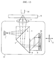
- Fig. 13 shows an optical head for an opto-magnetic recording and reproducing apparatus in accordance with a second embodiment of the present invention.
- a polarization beam splitter 3 having a back reflecting surface for phase difference compensation integrally formed thereon, an analyzer (polarization beam splitter) 9 for opto-magnetic differential detection, detectors 10, and a semiconductor laser device 1, which are the same as those of the first embodiment, are formed as miniaturized parts and are mounted on an actuator 12 in combination with an objective 2 forming an finite imaging system.
- the component parts of the optical system form one unit integrally driven.
- the distance between the light source 1 and the objective 2 is constant even when the actuator 12 is driven (in the direction of arrows 13). Therefore, it is possible to prevent intervention of an offset in a servo signal with a lens drive.
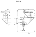
- Fig. 14 shows an optical head for an opto-magnetic recording and reproducing apparatus in accordance with a third embodiment of the present invention.
- a polarization beam splitter 3 having a back reflecting surface for phase difference compensation integrally formed thereon, an analyzer (polarization beam splitter) 9 for opto-magnetic differential detection, detectors 10, and a semiconductor laser device 1, which are the same as those of the first embodiment, are combined with a collimator lens 14, and a parallel beam is bent by a mirror 17 and is converged on an opto-magnetic recording medium 6 by an objective 15 forming an infinite imaging system.
- a parallel beam is bent by a mirror 17 and is converged on an opto-magnetic recording medium 6 by an objective 15 forming an infinite imaging system.
- the NA of the collimator lens is set to 0.20 or less and the refractive index of the vitreous material is set to 1.7 or more, thereby enabling the angle of incidence on the polarized light separating film to be limited within the range of about [the incident angle of the principal ray] ⁇ 6 °.
- a fixed head portion of the separated optical system head can be reduced in size.
- Fig. 15 shows an optical head for an opto-magnetic recording and reproducing apparatus in accordance with a fourth embodiment of the present invention.
- a semiconductor laser device 1, an objective 2, a polarized light separating film 4, the NA of the objective 2, and the vitreous material of a polarization beam splitter 18 are same as those in the first embodiment.
- the inclination of a phase compensating reflecting surface 19 is in an inverse relationship with that of the first embodiment. Therefore, the phase difference characteristics of the phase compensating reflecting surface 19 of the fourth embodiment are designed so as to satisfy the conditions described below.
- the reflectance of this compensating film is approximately 100 %, as in the first embodiment.
- a marginal ray incident at an angle of 45 + 6 ° on the polarized light separating film 4 is incident at an angle of 45 + 6 ° on the phase compensating film 19
- a marginal ray incident at an angle of 45 - 6 ° on the polarized light separating film 4 is incident at an angle of 45 - 6 ° on the phase compensating film 19. Therefore, the phase difference created by transmission through the polarized light separating film 4 is canceled at the time of reflection by the phase compensating film 19.
- the light source and the detection system cane be disposed on the same side.
- Fig. 16 shows an optical head for an opto-magnetic recording and reproducing apparatus in accordance with a fifth embodiment of the present invention.
- a divergent light beam emitted from a semiconductor laser device 1 provided as a light source is reflected by a polarized light separating film 22 of a polarization beam splitter 20, thereby being deflected toward an objective 2.
- the direction of polarization of the light beam emitted from the semiconductor laser device 1 is represented by lines 5, and the light beam has a polarized wave surface perpendicular to the plane of paper of Fig. 16.
- the light beam in this forward optical path is incident as an s-polarized component upon the polarization beam splitter 20.
- the polarized light separating film 22 has an s-polarized component reflectance ⁇ 82 %, 82 % of the quantity of light of the light beam in the forward optical path is deflected toward the objective 2.
- a detected light beam converged on the opto-magnetic recording medium 6 and reflected by the same travels through the objective 2 and passes as a convergent light beam through the polarized light separating film 22 of the polarization beam splitter
- a phase difference is created according to the incident angle.
- a Fresnel component corresponds to the s-polarized component while a Kerr component corresponds to the p-polarized component.
- the detected light beam transmitted through the polarization beam separating film 22 has a phase difference between the Fresnel component and the Kerr component. The phase difference varies with the incident angle.
- the graph of Fig. 17 shows an incident angle dependency of the phase difference of each polarized light component created at this time.
- the NA of the objective 2 on the light source side in the optical head optical system is small while the refractive index of the vitreous material is high.
- the NA of the objective 2 on the light source side is set to 0.19 or less and the refractive index of the vitreous material at operating wavelengths is set to 1.7 or more, thereby enabling the angle of incidence on the film to be limited within the range of about [the incident angle of the principal ray] ⁇ 6 °.
- the angle of marginal rays with respect to the principal ray is 10.4 °.
- a material having a refractive index of 1.79279 at operating wavelengths is selected as the vitreous material of the polarization beam splitter 20. Accordingly, the above-mentioned angle can be reduced to 5.8.
- the phase difference is about ⁇ 20 ° at the maximum, and a margin of an ordinary phase difference allowance is thereby removed nearly entirely. Therefore, it is difficult to directly put this arrangement to use. The condition becomes more unfavorable if the refractive index of the vitreous material is lower.
- the spot on the disk may have a radial coma, so that a diffraction ring (side robe) on one of the adjacent tracks is increased, resulting in occurrence of large cross-talk. Therefore, to reduce the track pitch, it is necessary to limit such a disk tilt. However, it is particularly difficult to limit such tilt to a required level of, for example, 2 to 3 mrad because of a reason relating to disk productivity.
- a method of disposing a limiting aperture for shutting off cross-talk components from adjacent tracks in the detected light beam may be used.
- an elliptical aperture having a width which is 55 to 90 %, more preferably 60 to 80 % of the diameter of the detected light beam in the radial direction (100 % in the tracking direction), or a 50 to 85 %, more preferably 55 to 75 % width rectangular aperture (100 % in the tracking direction) may be disposed in the optical path for the detected light beam.
- the above-mentioned diameter of the detected light beam is defined as a diameter at the position of the inserted aperture, since the detected light beam is a convergent beam.
- the angle of incidence of the principal ray on the polarized light separating film 22 is 45 °
- the phase difference is larger with respect to marginal rays having incident angles of 45 ⁇ 5.7 ° in this embodiment, as can be understood from the graph of Fig. 17.
- the maximum phase difference allowance is ⁇ 15 ° (indicated by arrows 25 in Fig. 17)
- the phase difference is limited within the allowance range (indicated by arrows 25 in Fig. 17) if rays in the light beam having the largest phase differences are limited to those incident at angles within the range of 45 ⁇ 3.5 ° on the polarized light separating film 22.
- the influence of the phase difference can be eliminated if the above-described limiting aperture is provided to act on the detected light beam transmitted through the polarization beam splitter 20 so that rays of the light beam having angles of incidence on the polarized light separating film 22 out of the range of 45 ⁇ 3.5 ° are cut off.
- This range of ⁇ 3.5 ° corresponds to angles of ⁇ 6.3 ° in air. Consequently, the NA of 0.18 the light beam may be reduced to NA of 0.11. In other words, the effective diameter of the detected light beam may be reduced to 62 % of the original diameter.
- the above-described limiting aperture is indicated at 21 in Fig. 16. It may have a rectangular shape or an elliptical shape such as not to stop marginal component rays located at the ends of the beam with respect to an axis perpendicular to the paper of Fig. 16, as shown in a lower right-hand portion of Fig. 16.
- the angle of incidence on the polarized light separating film 22 of marginal rays in the direction of azimuths of 90 ° and 270 ° has essentially no difference from the incident angle of 45 °. Therefore, the phase difference of light beam components in this direction is not a problem.
- the direction of polarization of the light beam in the forward optical path on the recording medium is set parallel to the guide grooves. Therefore, portions of the light beam adjacent to the two adjacent tracks are influenced by the phase difference created by transmission through the polarized light separating film 22. According to the present invention, therefore, it is possible to eliminate the influence of the phase difference together with the influence of cross-talk from adjacent tracks.
- a smaller optical system arrangement can be provided without using a back reflecting film for phase difference compensation.
- phase difference characteristics of the polarization beam splitter of the fifth embodiment is designed so as to satisfy the conditions described below.
- the present invention realizes a finite imaging system having more stable characteristics in an optical head used in an opto-magnetic recording and reproducing apparatus.
- the invention is applicable to an apparatus arranged to reproduce information from prerecorded optical recording media, and not arranged to record information. It will also be appreciated that the invention is applicable to an apparatus whose function is to record information on a recording medium, although such an apparatus will usually be capable of verifying the recorded information. Finally the invention is applicable to apparatus which is capable of both recording and reproducing information. The claims are to construed as covering all three types of apparatus.
Landscapes
- Physics & Mathematics (AREA)
- Optics & Photonics (AREA)
- Optical Head (AREA)
Applications Claiming Priority (4)
| Application Number | Priority Date | Filing Date | Title |
|---|---|---|---|
| JP28347194 | 1994-11-17 | ||
| JP283471/94 | 1994-11-17 | ||
| JP281654/95 | 1995-10-30 | ||
| JP7281654A JPH08212612A (ja) | 1994-11-17 | 1995-10-30 | 光学的情報記録再生装置及び該装置用光ヘッド |
Publications (2)
| Publication Number | Publication Date |
|---|---|
| EP0713212A2 true EP0713212A2 (fr) | 1996-05-22 |
| EP0713212A3 EP0713212A3 (fr) | 1997-03-05 |
Family
ID=26554268
Family Applications (1)
| Application Number | Title | Priority Date | Filing Date |
|---|---|---|---|
| EP95308123A Withdrawn EP0713212A3 (fr) | 1994-11-17 | 1995-11-14 | Appareil d'enregistrement et de reproduction optique d'information |
Country Status (3)
| Country | Link |
|---|---|
| US (1) | US5657305A (fr) |
| EP (1) | EP0713212A3 (fr) |
| JP (1) | JPH08212612A (fr) |
Families Citing this family (19)
| Publication number | Priority date | Publication date | Assignee | Title |
|---|---|---|---|---|
| US5867468A (en) * | 1996-03-11 | 1999-02-02 | Matsushita Electric Industrial Co., Ltd. | Optical pickup with a vertically movable aperture means |
| KR0176595B1 (ko) * | 1996-04-30 | 1999-04-15 | 김광호 | 대물렌즈장치 및 이 대물렌즈장치를 채용한 광픽업장치 |
| JPH1064078A (ja) * | 1996-08-20 | 1998-03-06 | Mitsubishi Electric Corp | 光ヘッド |
| US6031810A (en) * | 1996-09-18 | 2000-02-29 | Canon Kabushiki Kaisha | Using two laser sources on a magneto-optical recording medium for preventing light intensity shortage |
| JPH10106040A (ja) * | 1996-09-26 | 1998-04-24 | Canon Inc | 光学的情報記録媒体および光学的情報記録再生装置 |
| US6178151B1 (en) * | 1997-04-10 | 2001-01-23 | Matsushita Electric Industrial Co., Ltd. | Optical head having a reproducing optical system and filter formed by light passing therethrough |
| KR100478559B1 (ko) * | 1997-08-29 | 2005-07-21 | 삼성전자주식회사 | 기록및재생가능형디스크를위한광픽업 |
| US7804517B2 (en) * | 1998-07-31 | 2010-09-28 | Sony Corporation | Three-dimensional image-capturing apparatus |
| KR20010114255A (ko) * | 1999-05-11 | 2001-12-31 | 마츠시타 덴끼 산교 가부시키가이샤 | 광헤드 |
| JP3535996B2 (ja) * | 1999-09-20 | 2004-06-07 | 富士通株式会社 | 光記憶装置および位相補償量調整方法 |
| EP1223575B1 (fr) | 1999-10-06 | 2008-05-07 | Matsushita Electric Industrial Co., Ltd. | Lentille, tete optique, appareil d'enregistrement/de reproduction d'informations optiques, et procede d'enregistrement/de reproduction d'informations optiques a enregistrer/enregistrees sur un support |
| KR100813943B1 (ko) * | 2001-04-30 | 2008-03-14 | 삼성전자주식회사 | 복합 반사프리즘 및 이를 채용한 광픽업장치 |
| JP2005216337A (ja) * | 2004-01-27 | 2005-08-11 | Canon Inc | 光学的情報記録再生装置 |
| WO2005104111A1 (fr) * | 2004-04-21 | 2005-11-03 | Matsushita Electric Industrial Co., Ltd. | Detecteur de position d'ouverture de systeme optique a foyer commun, controleur de position d'ouverture de systeme optique a foyer commun, tete optique, processeur d’informations optiques et procede de detection de position d’ouverture de systeme optique a foyer commun |
| JP4523512B2 (ja) * | 2005-08-02 | 2010-08-11 | シャープ株式会社 | 光学ヘッドおよびディスク再生装置 |
| US7680013B2 (en) * | 2005-11-29 | 2010-03-16 | Canon Kabushiki Kaisha | Optical information recording and reproducing apparatus |
| US7791986B2 (en) * | 2006-03-15 | 2010-09-07 | Canon Kabushiki Kaisha | Optical information recording/reproducing apparatus |
| US20070285774A1 (en) * | 2006-06-12 | 2007-12-13 | The Boeing Company | Augmenting brightness performance of a beam-splitter in a stereoscopic display |
| JP2010238274A (ja) * | 2009-03-30 | 2010-10-21 | Sanyo Electric Co Ltd | 光ピックアップ装置 |
Citations (1)
| Publication number | Priority date | Publication date | Assignee | Title |
|---|---|---|---|---|
| JPH05234173A (ja) | 1992-02-26 | 1993-09-10 | Sony Corp | 光ディスク装置 |
Family Cites Families (24)
| Publication number | Priority date | Publication date | Assignee | Title |
|---|---|---|---|---|
| JPS60251533A (ja) * | 1984-05-25 | 1985-12-12 | Seiko Instr & Electronics Ltd | 光情報検出装置 |
| EP0176271B1 (fr) * | 1984-09-04 | 1991-01-02 | Matsushita Electric Industrial Co., Ltd. | Appareil d'entraînement pour milieu de mémoire optique |
| US5249171A (en) * | 1984-12-30 | 1993-09-28 | Olympus Optical Company Ltd. | Opto-magnetic pick-up device including phase difference correcting means |
| US4742218A (en) * | 1985-03-11 | 1988-05-03 | Hitachi, Ltd. | Focus error detection apparatus utilizing focusing an front and rear sides of focal planes |
| JPS6273444A (ja) * | 1985-09-27 | 1987-04-04 | Toshiba Corp | 光学ヘツド |
| JPS62164236A (ja) * | 1986-01-14 | 1987-07-20 | Matsushita Electric Ind Co Ltd | 光学的情報再生装置 |
| JPS62173650A (ja) * | 1986-01-28 | 1987-07-30 | Matsushita Electric Ind Co Ltd | 光学的情報再生装置 |
| EP0318912B1 (fr) * | 1987-11-30 | 1994-02-02 | Nec Corporation | Une tête optique |
| EP0331476A1 (fr) * | 1988-03-03 | 1989-09-06 | Canon Kabushiki Kaisha | Appareil magnéto-optique avec séparateur de faisceaux polarisant incliné à une angle de 45 degré aux autres parties du système |
| EP0339722B1 (fr) * | 1988-04-26 | 1993-10-06 | Koninklijke Philips Electronics N.V. | Dispositif pour explorer un support d'enregistrement magnéto-optique |
| DE68924303T2 (de) * | 1988-06-14 | 1996-02-29 | Nippon Electric Co | Optische Kopfanordnung. |
| US5072437A (en) * | 1988-09-19 | 1991-12-10 | Pioneer Electronic Corporation | Optical information reproducing apparatus |
| DE3913229A1 (de) * | 1988-09-19 | 1990-03-22 | Pioneer Electronic Corp | Wiedergabegeraet fuer optische informationen |
| JP2982965B2 (ja) * | 1989-09-18 | 1999-11-29 | オリンパス光学工業株式会社 | 光学式読み取り装置 |
| JPH0434740A (ja) * | 1990-05-30 | 1992-02-05 | Toshiba Corp | 光学ヘッド |
| JPH0487042A (ja) * | 1990-07-31 | 1992-03-19 | Sony Corp | 光学ピックアップ装置 |
| JPH04149840A (ja) * | 1990-10-12 | 1992-05-22 | Olympus Optical Co Ltd | 光学式情報読取り装置 |
| JPH04324129A (ja) * | 1991-04-23 | 1992-11-13 | Pioneer Electron Corp | 光ヘッド装置 |
| US5331622A (en) * | 1991-05-28 | 1994-07-19 | Applied Magnetics Corporation | Compact optical head |
| US5206852A (en) * | 1991-06-29 | 1993-04-27 | Samsung Electronics Co., Ltd. | High-density recording optical head |
| EP0745980B1 (fr) * | 1991-11-20 | 1999-06-16 | Sony Corporation | Dispositif de reproduction optique |
| US5350917A (en) * | 1991-12-27 | 1994-09-27 | Sony Corporation | Opto-magnetic recording polarization optical apparatus including a laser diode and a light absorbing film |
| US5359588A (en) * | 1992-02-12 | 1994-10-25 | Mitsubishi Denki Kabushiki Kaisha | Optical recording/reproducing apparatus |
| JPH06309725A (ja) * | 1993-04-22 | 1994-11-04 | Canon Inc | 2ビーム光ヘッド |
-
1995
- 1995-10-30 JP JP7281654A patent/JPH08212612A/ja active Pending
- 1995-11-09 US US08/554,937 patent/US5657305A/en not_active Expired - Fee Related
- 1995-11-14 EP EP95308123A patent/EP0713212A3/fr not_active Withdrawn
Patent Citations (1)
| Publication number | Priority date | Publication date | Assignee | Title |
|---|---|---|---|---|
| JPH05234173A (ja) | 1992-02-26 | 1993-09-10 | Sony Corp | 光ディスク装置 |
Also Published As
| Publication number | Publication date |
|---|---|
| EP0713212A3 (fr) | 1997-03-05 |
| JPH08212612A (ja) | 1996-08-20 |
| US5657305A (en) | 1997-08-12 |
Similar Documents
| Publication | Publication Date | Title |
|---|---|---|
| US5657305A (en) | Optical information recording and reproducing apparatus including a total reflection surface or a light shield plate disposed between a polarized light separating surface and a detection device for light beam compensation | |
| US5015835A (en) | Optical information reading and writing device with diffraction means | |
| KR100388515B1 (ko) | 광학픽업장치 | |
| EP0470807B1 (fr) | Appareil à disques optiques | |
| US4626679A (en) | Optical head and method of detecting the focus thereof | |
| US5684779A (en) | Optical head with forward and reflected light beams propagating through a dual diffraction grating device along a common path | |
| US5602383A (en) | Optical apparatus for optically reading and recording information | |
| USRE37717E1 (en) | Optical pickup device | |
| US5726962A (en) | Compact optical pickup device with beam splitter | |
| EP0363966B1 (fr) | Dispositif de tête optique | |
| KR100200873B1 (ko) | 광 픽업 장치 | |
| US4977552A (en) | Split type optical pick-up device with a tracking error detector on the moving part | |
| US6657942B2 (en) | Optical recording and reproducing apparatus having floating swing arm and optical disk for use therewith | |
| KR100200868B1 (ko) | 광픽업 장치 | |
| US6888786B2 (en) | Optical device and optical storage device | |
| US6876620B2 (en) | Optical storage device | |
| KR100200857B1 (ko) | 광픽업장치 | |
| KR100813945B1 (ko) | 광픽업장치 및 이에 적용되는 기록매체 | |
| US5579291A (en) | Compact-size magneto-optical head apparatus | |
| US6125091A (en) | Optical pickup apparatus for use with various types of optical disks | |
| US5471456A (en) | Optical medium recording apparatus with a rotatable optical beam deflector | |
| US20040208109A1 (en) | Objective optical system for correcting aberration and optical head employing the same | |
| KR100215792B1 (ko) | 편광 빔 분리기 및 이를 이용한 이종 광 디스크용 광 픽업 장치 | |
| JPH07121923A (ja) | 光学式ピックアップヘッド装置 | |
| JP3521893B2 (ja) | 光ピックアップ装置 |
Legal Events
| Date | Code | Title | Description |
|---|---|---|---|
| PUAI | Public reference made under article 153(3) epc to a published international application that has entered the european phase |
Free format text: ORIGINAL CODE: 0009012 |
|
| AK | Designated contracting states |
Kind code of ref document: A2 Designated state(s): DE FR GB IT NL |
|
| PUAL | Search report despatched |
Free format text: ORIGINAL CODE: 0009013 |
|
| AK | Designated contracting states |
Kind code of ref document: A3 Designated state(s): DE FR GB IT NL |
|
| 17P | Request for examination filed |
Effective date: 19970716 |
|
| 17Q | First examination report despatched |
Effective date: 19970819 |
|
| GRAH | Despatch of communication of intention to grant a patent |
Free format text: ORIGINAL CODE: EPIDOS IGRA |
|
| STAA | Information on the status of an ep patent application or granted ep patent |
Free format text: STATUS: THE APPLICATION IS DEEMED TO BE WITHDRAWN |
|
| 18D | Application deemed to be withdrawn |
Effective date: 20030902 |