EP0713227A1 - Kaltleiter und Vorrichtung zur Strombegrenzung mit mindestens einem Kaltleiter - Google Patents
Kaltleiter und Vorrichtung zur Strombegrenzung mit mindestens einem Kaltleiter Download PDFInfo
- Publication number
- EP0713227A1 EP0713227A1 EP95810680A EP95810680A EP0713227A1 EP 0713227 A1 EP0713227 A1 EP 0713227A1 EP 95810680 A EP95810680 A EP 95810680A EP 95810680 A EP95810680 A EP 95810680A EP 0713227 A1 EP0713227 A1 EP 0713227A1
- Authority
- EP
- European Patent Office
- Prior art keywords
- resistance
- ptc thermistor
- circuit
- layer
- current
- Prior art date
- Legal status (The legal status is an assumption and is not a legal conclusion. Google has not performed a legal analysis and makes no representation as to the accuracy of the status listed.)
- Granted
Links
Images


Classifications
-
- H—ELECTRICITY
- H02—GENERATION; CONVERSION OR DISTRIBUTION OF ELECTRIC POWER
- H02H—EMERGENCY PROTECTIVE CIRCUIT ARRANGEMENTS
- H02H9/00—Emergency protective circuit arrangements for limiting excess current or voltage without disconnection
- H02H9/02—Emergency protective circuit arrangements for limiting excess current or voltage without disconnection responsive to excess current
- H02H9/026—Current limitation using PTC resistors, i.e. resistors with a large positive temperature coefficient
-
- H—ELECTRICITY
- H01—ELECTRIC ELEMENTS
- H01C—RESISTORS
- H01C1/00—Details
- H01C1/08—Cooling, heating or ventilating arrangements
-
- H—ELECTRICITY
- H01—ELECTRIC ELEMENTS
- H01C—RESISTORS
- H01C1/00—Details
- H01C1/08—Cooling, heating or ventilating arrangements
- H01C1/082—Cooling, heating or ventilating arrangements using forced fluid flow
-
- H—ELECTRICITY
- H01—ELECTRIC ELEMENTS
- H01C—RESISTORS
- H01C7/00—Non-adjustable resistors formed as one or more layers or coatings; Non-adjustable resistors made from powdered conducting material or powdered semi-conducting material with or without insulating material
- H01C7/02—Non-adjustable resistors formed as one or more layers or coatings; Non-adjustable resistors made from powdered conducting material or powdered semi-conducting material with or without insulating material having positive temperature coefficient
Definitions
- the invention is based on PTC thermistors according to the preambles of patent claims 1 and 5 and a device for current limitation with at least one PTC thermistor according to the preamble of patent claim 7.
- the invention relates to a prior art, as is known from DE 39 42 266 C1.
- the heat developed by a PTC radiator is dissipated via its electrodes to a hollow support profile made of aluminum, which is electrically insulated from the electrodes by an insulating film.
- a leaf spring anchored in the carrier profile body presses against its relatively thin top wall.
- the invention relates to a prior art, as is known from DE-OS 27 15 878.
- a resistance body made of a material with a positive temperature coefficient of resistance together with its electrodes embedded in a mass of 30 M% silicone rubber and 70 M% magnesium oxide and gives the generated in it Heat off an aluminum heating tube of a styling stick.
- This heater is suitable for a continuous use temperature up to 149 ° C.
- the invention relates to a prior art, as is known from DE-AS 1 204 302.
- two thermistors connected in series are arranged in a first electric circuit, two varistors connected in series in an electrically parallel second electric circuit and a switch in a further third electric circuit connected in parallel.
- This is a current commutation circuit in which the thermistors based on barium oxide and barium titanate, which can only carry a few amperes of continuous current, are unloaded in continuous operation.
- CH-PS 581 377 from which a PTC thermistor component with a ceramic PTC resistor is known, which is cooled at its electrodes. Its edge-side insulating protective layer made of epoxy resin is poorly heat-conducting.
- DE-AS 1 253 332 discloses a commutation circuit for switching off high currents, in which normal conductors are thermally coupled to PTC thermistors and are electrically connected in series. Here too, the PTC thermistors do not carry continuous current.
- DE 41 05 786 A1 discloses a meandering normal resistor consisting of two partial resistors arranged in mirror image in one plane, which is applied to an electrically insulating and thermally highly conductive ceramic heat sink using thin-film or screen printing technology. A relatively high inductance of this resistor is undesirable.
- a liquid-cooled, low-inductance resistor in which a resistance wire is guided in a zigzag manner in grooves in a plate-shaped ceramic molded part, which is pressed against a heat sink with flow channels. Resistance wire and ceramic molded part are coated with a glaze to reduce creepage distances.
- the invention solves the problem of further developing PTC thermistors and current limiting devices of the type mentioned in such a way that they carry a continuous current of more than 100 A and short-circuit currents within 10 microseconds Limit value that is below the destruction limit of passive components of the electrical systems or circuits to be protected.
- An advantage of the invention is that protective devices operated with these PTC thermistors work reversibly, respond without arcing, and can be used in a low-inductance and space-saving manner.
- the protection circuits are low-loss, vibration-proof and can be integrated into an existing cooling circuit; they respond autonomously and enable flexible application. The reliability of the protection system is not affected by additional electronic assemblies and components.
- short-circuit currents can be limited within 10 microseconds to values which are below the destruction limit of active components of the electrical systems or circuits to be protected. Cooling of the active part of the devices for current limitation is essential. This cooling can be integrated into the cooling circuit of an already existing liquid cooling.
- the short circuit behavior of the protective circuits can be flexibly adapted to the different electrical characteristics of different converter types by adapting the active part dimensioning of the PTC thermistors.
- the PTC thermistors With the PTC thermistors according to the invention, it is possible to decouple the energy stored internally in a converter from a capacitor bank from a short circuit in the converter switches or semiconductors.
- the devices for current limiting can be arranged either in the DC link or in the phase modules. Due to the modularity of the intermediate circuit capacitor battery, which may have up to 40 capacitors connected in parallel, the short-circuit protection can optionally be arranged on one or more capacitors connected in parallel.
- 1 shows a line converter or 1st converter (1) which is electrically connected on the DC voltage side to a drive converter or 2nd converter (8) via a DC voltage intermediate circuit (2).
- the DC voltage intermediate circuit (2) has a filter for damping intermediate circuit harmonics from a series connection of a filter choke (LF) and a filter capacitor (CF) on; further DC link capacitors or capacitors (C1, C2, C3), the capacitors (C2, C3) each being connected in series with a reversible short-circuit current limiter (3).
- LF filter choke
- CF filter capacitor
- the reversible short-circuit current limiter (3) has a parallel connection of a diode (4) which is polarized in the blocking direction of a short-circuit path, a PTC resistor or PTC thermistor (5) and a shunt resistor branch (6) which comprises a surge arrester or varistor (7), cf. . 3 - 5.
- the PTC thermistor (5) and the shunt resistor branch (6) are always present in the short-circuit current limiter (3); the diode (4) can be connected in parallel.
- the two converters (1, 8) are designed as 2-point converters, with only two main valve branches with 2 GTO thyristors (T1, T2) as main valves for an AC phase connected to an AC voltage terminal ( 10) can be tapped, are shown.
- T1, T2 2 GTO thyristors
- 6 main valve branches of the same type are required.
- a thyristor circuit (9) is provided in parallel with each main valve (T1, T2), only the one for the GTO thyristor (T1) being shown for the sake of clarity. It goes without saying that the thyristor circuit (9) could also have a different circuit than the one shown.
- a choke or di / dt limiting choke (L) is connected to the positive pole (P) of the DC link (2) via a reversible short-circuit current limiter (3).
- a diode with an ohmic resistor is connected in series in a parallel branch to the di / dt limiting choke (L).
- This di / dt limiting choke (L) can be kept very small or omitted when using the short-circuit current limiter (3) according to the invention.
- the reversible short-circuit current limiter (3) in the second converter (8) can be omitted if reversible Short-circuit current limiters (3) are provided in the DC voltage intermediate circuit (2).
- the reversible short-circuit current limiter (3) in the direct voltage intermediate circuit (2) can be omitted if a reversible short-circuit current limiter (3) is provided in the second converter (8).
- FIG. 2 shows, as a second exemplary embodiment, a converter circuit similar to FIG. 1, which has 1. and 2. 3-point converters (11, 12) instead of 1. and 2. 2-point converters (1, 8). The same components are labeled the same.
- a reversible short-circuit current limiter (3) is connected in series to a capacitor bank, which has a plurality of capacitors connected in parallel, in a DC voltage intermediate circuit (2 ') for each potential half.
- the advantage of this circuit is a cost reduction of the protective circuit, since fewer reversible short-circuit current limiters (3, 3 ') are required, or in a lower system diversification, since fewer types of reversible short-circuit current limiters (3, 3') are required for the converter range.
- di / dt limiting chokes (L1, L2) are connected in series to the main valves of each main valve branch, which are connected to the positive pole (P) or to the negative pole (N) of the DC voltage intermediate circuit (2 ' ) are electrically connected. They can be very small or left out.
- a dashed-line reversible short-circuit current limiter (3 ') can be provided in the zero point or midpoint path of the converter (12), which reversible short-circuit current limiter (3') on the one hand with a midpoint conductor (13 ') of this midpoint path and on the other hand with a midpoint conductor (13 ) of the DC voltage intermediate circuit (2 ') is electrically connected. This will make for many Adequate protection is provided by accidents.
- reversible short-circuit current limiters (3, 3 ') in the second converter (12) can also be omitted in this exemplary embodiment if reversible short-circuit current limiters (3) in the DC voltage intermediate circuit (2') ensure the desired protection, and vice versa.
- any short-circuit discharge currents of the capacitors (C2, C3) are limited to values which are at least below the destruction limit of the passive components and the busbars, ideally below the destruction limit of the active components.
- the response times of the protective circuit required for this are within 10 ⁇ s.
- the protective circuits according to FIGS. 1 and 2 ensure good protection both in the event of a partial short circuit and a full short circuit of a converter (1, 8; 11, 12).
- the thermal continuous current load on the reversible short-circuit current limiter (3, 3 ') can be reduced.
- the diode (4) conducts the DC link pulse frequency for half a period, thus reducing the effective current.
- the diode (4) blocks and the protective function of the reversible short-circuit current limiter (3, 3 ') is fully effective.
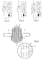
- Fig. 3 shows a short-circuit current limiter (3) in which a shunt resistor branch (6) with a series connection of a varistor (7), an ohmic resistor (14) and a choke or to a PTC thermistor (5) in a 1st or main current path Inductance (30) is connected in parallel.
- the PTC thermistor (5) heats up above its response temperature, so that its resistance rises sharply and limits the current. Thermal destruction of the PTC thermistor (5) is avoided by commutation of the short-circuit current on the shunt resistor branch (6).
- the short-circuit current is limited to values that are harmless to the DC link (2).
- the PTC thermistor (5) cools down and is ready for operation again.
- the PTC thermistor (5) can be a non-blocking PTC thermistor on a metal base with resistance jumps to about 10 times, preferably less than 100 times its cold resistance, or a blocking PTC thermistor based on filled polymers, the resistance jumps to more than 100 times, preferably have more than 104 times the cold resistance.
- a varistor (7) preferably based on metal oxide, the maximum permissible continuous operating voltage of which is preferably below the operating voltage of the direct voltage intermediate circuit (2).
- a PTC thermistor (15) blocking or not blocking at the operating voltage according to FIG. 4 can be used instead of the ohmic resistor (14) according to FIG. 3, a PTC thermistor (15) blocking or not blocking at the operating voltage according to FIG. 4 can be used.
- both PTC thermistors (5, 15) have a resistance-temperature characteristic with high jumps in resistance to resistance values that are significantly greater than 100 times, preferably greater than 10 times the cold resistance value (blocking PTC thermistor (5)), a current-blocking behavior of the overall circuit can be achieved .
- the short-circuit current limiter (3) according to FIG. 5 differs from that of FIG. 4 in that a non-blocking PTC thermistor (5) is connected in series with a blocking PTC thermistor (5 ') in the main current path.
- the blocking PTC thermistor (5 ') is designed so that its resistance increases only after the non-blocking PTC thermistor (5) has responded, ie that it responds with a time delay, cf. e.g. B. the aforementioned CH-A-581 377. This relieves the PTC thermistor (5 ') electrically and thermally.
- the PTC thermistor (15) can be replaced by an ohmic resistor (14) according to FIG. 3.
- the circuit according to FIG. 5 is suitable to protect even under overload conditions, the varistor (7) remaining blocking. In this case, the continuous operating voltage of the varistor (7) must be higher than the operating voltage of the DC link (2).
- the inductance (30), which is preferably provided in the shunt resistor branch (6), can improve the current limiting behavior of the overall circuit.
- Fig. 6 shows the shape of a resistance track of a non-blocking PTC thermistor (5), which is formed in its central part meandering and symmetrical with respect to a sectional plane (A - A ').
- the starting point is a metal foil, which can be cut using a conventional cutting process, e.g. B. water jet cutting or laser cutting, or is structured by a photolithographic process in the central part meandering.
- resistance-forming meandering tracks (16) are divided at least once, but preferably several times, by elongated cutouts (19) parallel to one another in their longitudinal direction, cf. the partial representation of a meandering track (16) in a section (17).
- recess-free cooling islands (18) with a predeterminable longitudinal distance (a), which allow an increased nominal current carrying capacity without affecting the dynamic response behavior under short-circuit conditions.
- With increasing longitudinal distance (a) of the individual recesses (19) from one another the nominal current carrying capacity can continue to increase be improved.
- Further cooling islands (18 ') are provided at the ends of the meandering tracks (16).
- a particularly low-inductance structure with symmetrical supply and return of the current is achieved by folding the structured metal foil around the sectional plane (A - A ') by 180 °.
- a preferably ferromagnetic metal or a metal alloy can be used as the starting basis for the non-blocking PTC thermistor (5).
- Materials based on nickel, iron or cobalt and their alloys are particularly suitable.
- the particularly high positive temperature coefficient of the specific resistance of these materials compared to nonferromagnetic pure metals has a nonlinear behavior which is favorable for the application, with a maximum in the range of the Curie temperature.
- nonferromagnetic metals such as beryllium or ruthenium, with a temperature coefficient of resistance of> 4 ⁇ 10 ⁇ 3 K ⁇ 1 can be used.
- the necessary dynamic response behavior of the PTC thermistor (5) under short-circuit conditions is achieved by the formation of a small cross-sectional area of the active part.
- Typical values of the cross-sectional area for a circuit according to FIGS. 1 and 2 are in the range from 0.1 mm to 5 mm, preferably in the range from 0.5 mm to 1.5 mm.
- the cold resistance values at room temperature are in the range of a few 10 m ⁇ - 100 m ⁇ .
- Fig. 7 shows the basic structure of a non-blocking, earth potential-free PTC thermistor (5), the The resistance track is shown in FIG. 6, in an exploded view, in sections in cross section in a sectional plane (B - B ') orthogonal to the sectional plane (A - A') in FIG. 6.
- the cooling element (25) has, adjacent to the 1st main surface of the ceramic layer (20), cooling slots (26) through which electrically conductive water (process water) flows, preferably turbulently, during operation.
- One of the 1st main surface opposite the 2nd main surface of the ceramic layer (20) is provided with an electrically insulating heat-conducting layer (21), e.g. B. from oil or a thermal paste based on silicone, covered with a thickness in the range of 10 microns - 100 microns.
- Meander tracks (16) of the resistance body of the PTC thermistor (5), cf. Fig. 6, are between this heat-conducting layer (21) and an electrically insulating, preferably thermally conductive, flexible, high temperature-resistant polymer film (22), for.
- a pressure compensation cushion or pressure compensation element (23) can be provided for pressing on, which is acted upon by a force (F) orthogonal to the second main surface of the ceramic layer (20).
- the pressure compensation element (23) z. B. consist of a thin, flexible metal foil which is welded to a closed shell and has a thickness in the range of 0.2 cm - 3 cm.
- the pressure compensation element (23) is filled with a dielectric or electrically conductive fluid (24) with a boiling temperature preferably above 150 ° C. As high-boiling fluids (24) z. B.
- carboxylate esters polyol esters, polymeric dimethylsiloxanes or aliphatic pentaerythritol esters can be used.
- a further heat sink can be in direct contact with the Pressure compensation element (23) are brought.
- the pressure compensation element (23) achieves, on the one hand, a uniform pressing of the resistance tracks (16) against the ceramic layer (20) and, on the other hand, compensation cooling by convection to protect the resistance tracks (16) from partial overheating.
- the pressure compensation element (23) can be omitted in particular if the high-temperature-resistant polymer film (22) consists of silicone elastomer or another elastomer material, a thickness in the range of 1.5 mm - 10 mm and a Shore hardness in the range of 10 Shore A - 100 Shore A.
- the resistance or meander tracks (16) of the PTC thermistor (5) are here in a with inorganic, thermally conductive particles, such as. B. from AlN, BN, Al2O3, filled polymer matrix (27) integrated or embedded.
- the polymer matrix (27) consists of high-temperature thermosets and / or elastomers and / or high-temperature thermoplastics.
- the polymer matrix (27) preferably consists of polyether ether ketones (PEEK) and / or polyether imides (PEI) and / or polysulfones (PSU) and / or polyether sulfones (PES).
- a bimodally distributed powder is preferably used as the filler, ie a powder whose particle size or diameter has at least 2 frequency maxima.
- the maximum degree of filling of 62% by volume which is generally achieved cf. the publication by P. Bujard and JP Ansermet mentioned at the beginning can be further increased.
- the elastic properties of the polymer matrix (27) allow good thermal contact with their edge-side metallic heat sinks or cooling elements (25), which are preferably cooled by a mixture of water and glycol.
- At least approximately geometrically congruent resistance or meandering tracks (16) are embedded in the polymer matrix (27), through which an electric current is conducted in anti-parallel.
- Dashed lines indicate an electrical line (28) which electrically connects the meandering tracks (16) on the face side in such a way that adjacent meandering tracks (16) are traversed by the current in an antiparallel direction.
- an approximately 1 ⁇ m thick Cr / Ni layer is applied as an adhesive layer (29) to the meander tracks (16) on one or both sides.
- a nickel or iron layer is applied to this adhesive layer (29) by means of a galvanic chemical process or a soldering process.
- a solder layer or another metal layer e.g. B. made of tungsten. If iron is used, a nickel or aluminum layer can be applied as corrosion protection in a second step.
- the meandering tracks (16) are in electrically and thermally highly conductive contact with a ceramic layer (20), two meandering tracks (16) each lying at least approximately geometrically congruently on the ceramic layer (20). Similar to FIG. 8, the ceramic layer (20) and the meander tracks (16) of the PTC thermistor (5) are embedded in a polymer matrix (27) and cooled by means of cooling elements (25) on the edge, preferably by a mixture of water and glycol.
Landscapes
- Engineering & Computer Science (AREA)
- Microelectronics & Electronic Packaging (AREA)
- Physics & Mathematics (AREA)
- Ceramic Engineering (AREA)
- Electromagnetism (AREA)
- Fluid Mechanics (AREA)
- Power Engineering (AREA)
- Thermistors And Varistors (AREA)
- Emergency Protection Circuit Devices (AREA)
Abstract
Description
- Bei der Erfindung wird ausgegangen von Kaltleitern nach den Oberbegriffen der Patentansprüche 1 und 5 und von einer Vorrichtung zur Strombegrenzung mit mindestens einem Kaltleiter nach dem Oberbegriff des Patentanspruchs 7.
- Mit dem Oberbegriff des Patentanspruchs 1 nimmt die Erfindung auf einen Stand der Technik Bezug, wie er aus der DE 39 42 266 C1 bekannt ist. Dort wird die von einem PTC-Heizkörper entwickelte Wärme über dessen Elektroden an einen hohlen Trägerprofilkörper aus Aluminium abgeführt, der gegenüber den Elektroden durch eine Isolierfolie elektrisch isoliert ist. Eine im Trägerprofilkörper verankerte Blattfeder drückt gegen dessen relativ dünne Oberwand.
- Es handelt sich hierbei um eine Niederspannungsanwendung eines PTC-Heizkörpers mit geringer Anforderung an die elektrische Isolation.
- Mit dem Oberbegriff des Patentanspruchs 5 nimmt die Erfindung auf einen Stand der Technik Bezug, wie er aus der DE-OS 27 15 878 bekannt ist. Dort ist ein Widerstandskörper aus einem Material mit einem positiven Temperaturkoeffizienten des Widerstandes mitsamt seinen Elektroden in eine Masse aus 30 M% Silikongummi und 70 M% Magnesiumoxid eingebettet und gibt die in ihm erzeugte Wärme an ein Aluminium-Heizrohr eines Frisierstabes ab. Diese Heizvorrichtung ist für eine Dauergebrauchstemperatur bis 149 °C geeignet.
- Mit dem Oberbegriff des Patentanspruchs 7 nimmt die Erfindung auf einen Stand der Technik Bezug, wie er aus der DE-AS 1 204 302 bekannt ist. In der dort angegebenen Schalteinrichtung zum Unterbrechen von Stromkreisen sind 2 in Reihe geschaltete Thermistoren in einem 1. Stromkreis, 2 in Reihe geschaltete Varistoren in einem elektrisch parallelgeschalteten 2. Stromkreis und ein Schalter in einem weiteren parallelgeschalteten 3. Stromkreis angeordnet. Es handelt sich hierbei um eine Stromkommutationsschaltung, bei der die Thermistoren auf der Basis von Bariumoxid und Bariumtitanat, die nur wenige Ampere Dauerstrom tragen können, im Dauerbetrieb unbelastet sind.
- Aus der US-A-4,583,146 ist es ebenfalls bekannt, zur Gewährleistung eines lichtbogenarmen Löschens in Parallel zweigen zu einem mechanischen Unterbrecherkontakt einen Kaltleiter und einen Varistor zu schalten. Der Kaltleiter kann endseitig eine dünne Varistorschicht aufweisen. Beim öffnen des mechanischen Schalters kommutiert der Strom von diesem auf den Kaltleiter und Varistor.
- In Schaltungen ohne Unterbrecherkontakt ist das dynamische Ansprechverhalten einer derartigen Strombegrenzerschaltung unbefriedigend.
- Aus der CH-A-581 377 ist es bekannt, einen Kaltleiter zu einem Festwiderstand und zu einem thermisch oder magnetisch auslösbaren 1. Schalter parallelzuschalten, wobei in Reihe zu dieser Parallelschaltung ein spannungaufbauender 2. Schalter vorgesehen ist. Dabei wird der Kaltleiter erst im Kurzschlußfall belastet, erhöht dabei seinen Widerstand und ermöglicht ein weitgehend lastfreies Schalten des 2. Schalters. Anstelle eines Kaltleiters können mehrere unterschiedliche Kaltleiter parallelgeschaltet sein, die zeitlich nacheinander ansprechen.
- Aus der Veröffentlichung von P. Bujard und J. P. Ansermet, THERMALLY CONDUCTIVE ALUMINIUM NITRIDE-FILLED EPOXY in: 5. IEEE SEMI-THERM Symposium (1989), S. 126 - 130, ist es bekannt, bei einer mit Aluminiumnitrid (AlN) gefüllten Polymermatrix, wie sie zur Herstellung von Kaltleitern geeignet ist, einen Füllgrad von 62 Vol% zu erreichen.
- Bei Stromrichtern, die einen Gleichspannungszwischenkreis aufweisen, können im Kurzschlußfall durch eine impedanzarme Entladung der Zwischenkreiskondensatoren sehr hohe Kurzschlußströme im Zwischenkreis auftreten, die ohne Schutzmaßnahme zur Zerstörung von aktiven Bauelementen führen können und Konstruktionsteile mit hohen Kräften beanspruchen und verformen.
- Aus der DE 3 710 799 A1 ist es bekannt, bei einer Wechselrichterschaltung in Reihenschaltung zu Kondensatoren eine Schmelzsicherung vorzusehen, die durchschmilzt und den Schaltkreis unterbricht, wenn ein Gleichstromkondensator kurzgeschlossen wird. Es vergeht eine Zeitspanne von ggf. einigen 100 ms ab dem Zeitpunkt des Kurzschlusses der Leitungen der Wechselrichterschaltung, bevor ein Detektor für das Durchschmelzen der Sicherung verzögert diesen Kurzschluß wahrnimmt. Wahrgenommen wird nur ein interner Kurzschluß eines Gleichstromkondensators. Bei einem internen Kurzschluß eines Kondensators werden dadurch die zugehörigen Geräte und Schaltungen geschützt. Anstelle der Schmelzsicherung kann auch für Gruppen von in Reihe geschalteten Gleichstromkondensatoren als Störungsdetektor ein Differentialverstärker vorgesehen sein, der eine Störung anhand einer Potentialdifferenz detektiert.
- Für Traktionsstromrichter, die erhöhten Vibrations- und Stoßbeanspruchungen ausgesetzt sind, ist der Einsatz herkömmlicher Schmelzsicherungen auf Grund ihrer geringen Zuverlässigkeit nicht möglich bzw. von den Bahnbetreibern unerwünscht. Schmelzsicherungen sind große Bauelemente mit viel Verkabelungsaufwand, die hohe Gegenspannungen aufbauen, was für den Betrieb von Stromrichtern mit abschaltbaren Halbleitern störend ist. Geforderte Ansprechempfindlichkeiten von weniger als 100 µs sind schwer, wenn überhaupt, ausführbar.
- Wünschenswert für den Stromrichterbetrieb ist eine deutliche Reduktion bzw. der Entfall der Zwischenkreisinduktivität. Ohne Schutzmaßnahme steigen jedoch hierdurch im Kurzschlußfall die Kurzschlußstromamplituden auf Werte bis zu 1 MA an, die derzeit in Traktionssystemen mit Stromrichtern mechanisch nicht beherrscht werden können.
- Zum einschlägigen Stand der Technik wird ferner auf die CH-PS 581 377 verwiesen, aus der ein Kaltleiter-Bauelement mit einem keramischen PTC-Widerstand bekannt ist, der an seinen Elektroden gekühlt wird. Seine randseitige isolierende Schutzschicht aus Epoxidharz ist schlecht wärmeleitend.
- Aus der US-PS 3,996,447 ist es bekannt, bei einem Heizkörper mit einem PTC-Widerstand zwischen Elektroden und Kühlkörper eine Wärmeleitpaste anzubringen, nicht jedoch an der Mantelfläche.
- Aus dem deutschen Gebrauchsmuster G 91 00 865.4 ist ein flüssigkeitsgekühlter, niederinduktiver, geschlitzter Hochlastwiderstand mit wenigstens 2 voneinander beabstandeten, deckungsgleichen Widerstandsbahnen bekannt, bei dem die Widerstandsbahnen elektrisch so miteinander verbunden sind, daß der Strom in antiparalleler Richtung fließen kann. Die Widerstandsbahnen sind einerseits mit einem Trägerkörper und andererseits mit elektrisch isolierenden, wärmeleitenden Scheiben verklebt, welche die erzeugte Wärme an Flüssigkeitskühlkörper ableiten.
- Aus der DE-AS 1 253 332 ist eine Kommutationsschaltung zum Abschalten hoher Ströme bekannt, bei der Normalleiter mit Kaltleitern thermisch gekoppelt und elektrisch in Reihe geschaltet sind. Auch hier tragen die Kaltleiter keinen Dauerstrom.
- Aus der DE 41 05 786 A1 ist ein mäanderförmiger Normalwiderstand aus 2 spiegelbildlich in einer Ebene angeordneten Teilwiderständen bekannt, der in Dünnfilm- oder Siebdrucktechnik auf einen elektrisch isolierenden und thermisch gutleitenden Keramikkühlkörper aufgebracht ist. Unerwünscht ist eine relativ hohe Induktivität dieses Widerstandes.
- Aus der DE 33 38 709 A1 ist ein flüssigkeitsgekühlter, niederinduktiver Widerstand bekannt, bei dem ein Widerstandsdraht zickzackförmig in Nuten eines plattenförmigen Keramikformteils geführt ist, welches an einen Kühlkörper mit Strömungskanälen angepreßt wird. Zur Verkleinerung von Kriechstrecken sind Widerstandsdraht und Keramikformteil mit einer Glasur überzogen.
- Die Erfindung, wie sie in den Patentansprüchen 1, 5 und 7 definiert ist, löst die Aufgabe, Kaltleiter und Vorrichtungen zur Strombegrenzung der eingangs genannten Art derart weiterzuentwickeln, daß sie einen Dauerstrom von mehr als 100 A führen und Kurzschlußströme innerhalb von 10 µs auf einen Wert begrenzen können, der unterhalb der Zerstörungsgrenze von passiven Komponenten der zu schützenden elektrischen Anlagen oder Schaltkreise liegt.
- Ein Vorteil der Erfindung besteht darin, daß mit diesen Kaltleitern betriebene Schutzeinrichtungen reversibel arbeiten, lichtbogenfrei ansprechen sowie niederinduktiv und raumsparend einsetzbar sind. Die Schutzschaltungen sind verlustarm, rüttelfest und in einen bestehenden Kühlkreislauf integrierbar; sie sprechen autonom an und ermöglichen eine flexible Applikation. Die Zuverlässigkeit des Schutzsystems wird durch zusätzliche elektronische Baugruppen und Komponenten nicht beeinträchtigt.
- Werden die Strombegrenzerschaltungen in Reihenschaltung zu Stromrichterventilen eingesetzt, so kann auf eine Stromanstiegsbegrenzungsdrossel verzichtet werden.
- Gemäß einer vorteilhaften Ausgestaltung der Erfindung können Kurzschlußströme innerhalb von 10 µs auf Werte begrenzt werden, die unterhalb der Zerstörungsgrenze von aktiven Komponenten der zu schützenden elektrischen Anlagen oder Schaltkreise liegen. Dabei ist eine Kühlung des Aktivteils der Vorrichtungen zur Strombegrenzung unerläßlich. Diese Kühlung kann bei einer schon vorhandenen Flüssigkeitskühlung in deren Kühlkreislauf integriert werden.
- Durch Anpassung der Aktivteilbemessung der Kaltleiter kann das Kurzschlußverhalten der Schutzschaltungen den unterschiedlichen elektrischen Kennwerten verschiedener Stromrichtertypen flexibel angepaßt werden.
- Mit den erfindungsgemäßen Kaltleitern ist es möglich, die intern in einem Stromrichter gespeicherte Energie einer Kondensatorbank von einem Kurzschluß in den Stromrichterschaltern bzw. Halbleitern zu entkoppeln. Dabei können die Vorrichtungen zur Strombegrenzung entweder im Gleichspannungszwischenkreis oder in den Phasenbausteinen angeordnet werden. Auf Grund der Modularität der Zwischenkreis-Kondensatorbatterie, die ggf. bis zu 40 parallelgeschaltete Kondensatoren aufweist, kann der Kurzschlußschutz wahlweise an einem oder an mehreren parallelgeschalteten Kondensatoren angeordnet werden.
- Die Erfindung wird nachstehend anhand von Ausführungsbeispielen erläutert. Es zeigen:
- Fig. 1
- eine 2Punkt-Stromrichterschaltung mit einem Antriebsstromrichter, der über einen Gleichspannungszwischenkreis mit einem Netzstromrichter verbunden ist, wobei im Kurzschlußpfad von Kondensatoren des Gleichspannungszwischenkreises ein reversibler Strombegrenzer angeordnet ist,
- Fig. 2
- eine Stromrichterschaltung gemäß Fig. 1 mit 3Punkt-Stromrichtern,
- Fig. 3 - 5
- unterschiedliche Strombegrenzerschaltungen mit Kaltleitern, Varistoren und Induktivitäten,
- Fig. 6
- eine konstruktives Ausführungsbeispiel der Widerstandsbahn eines Kaltleiters einer Strombegrenzerschaltung gemäß den Fig. 3 - 5,
- Fig. 7
- den Prinzipaufbau eines erdpotentialfrei betreibbaren Kaltleiters mit Brauchwasserkühlung für große elektrische Leistungen sowie
- Fig. 8 und 9
- den Prinzipaufbau von besonders niederinduktiven Kaltleitern.
- Fig. 1 zeigt einen Netzstromrichter oder 1. Stromrichter (1), der gleichspannungsseitig über einen Gleichspannungszwischenkreis (2) mit einem Antriebsstromrichter bzw. 2. Stromrichter (8) elektrisch verbunden ist.
- Der Gleichspannungszwischenkreis (2) weist zwischen einem positiven Pol bzw. einer positiven Polplatte (P) und einem negativen Pol bzw. einer negativen Polplatte (N) ein Filter zur Dämpfung von Zwischenkreisoberschwingungen aus einer Reihenschaltung einer Filterdrossel (LF) und eines Filterkondensators (CF) auf; ferner Zwischenkreiskondensatoren bzw. Kondensatoren (C1, C2, C3), wobei die Kondensatoren (C2, C3) mit je einem reversiblen Kurzschlußstrombegrenzer (3) in Reihe geschaltet sind. Der reversible Kurzschlußstrombegrenzer (3) weist eine Parallelschaltung einer in Sperrichtung eines Kurzschlußpfades gepolten Diode (4), eines PTC-Widerstandes bzw. Kaltleiters (5) und eines Nebenschlußwiderstandszweiges (6) auf, der einen Überspannungsableiter bzw. Varistors (7) umfaßt, vgl. die Fig. 3 - 5. Der Kaltleiter (5) und der Nebenschlußwiderstandszweig (6) sind im Kurzschlußstrombegrenzer (3) stets vorhanden; die Diode (4) kann parallelgeschaltet sein.
- Die beiden Stromrichter (1, 8) sind als 2Punkt-Stromrichter ausgeführt, wobei für den Stromrichter (8) in Fig. 1 nur zwei Hauptventilzweige mit 2 GTO-Thyristoren (T1, T2) als Hauptventilen für eine Wechselstromphase, die an einer Wechselspannungsklemme (10) abgreifbar ist, gezeigt sind. Für 3phasigen Wechselstrom sind entsprechend 6 gleichartig aufgebaute Hauptventilzweige erforderlich. Parallel zu jedem Hauptventil (T1, T2) ist eine Thyristorbeschaltung (9) vorgesehen, wobei der Übersichtlichkeit halber nur diejenige zum GTO-Thyristor (T1) dargestellt ist. Es versteht sich, daß die Thyristorbeschaltung (9) auch eine andere Schaltung als die dargestellte aufweisen könnte. Im Strompfad der beiden Hauptventile (T1, T2) ist eine Drossel bzw. di/dt-Begrenzungsdrossel (L) über einen reversiblen Kurzschlußstrombegrenzer (3) mit dem positiven Pol (P) des Gleichspannungszwischenkreises (2) verbunden. In einem Parallelzweig zur di/dt-Begrenzungsdrossel (L) ist eine Diode mit einem ohmschen Widerstand in Reihe geschaltet. Diese di/dt-Begrenzungsdrossel (L) kann bei Verwendung des erfindungsgemäßen Kurzschlußstrombegrenzers (3) sehr klein gehalten werden oder entfallen.
- Der reversible Kurzschlußstrombegrenzer (3) im 2. Stromrichter (8) kann entfallen, wenn reversible Kurzschlußstrombegrenzer (3) im Gleichspannungszwischenkreis (2) vorgesehen sind. Andererseits können die reversiblen Kurzschlußstrombegrenzer (3) im Gleichspannungszwischenkreis (2) entfallen, wenn ein reversibler Kurzschlußstrombegrenzer (3) im 2. Stromrichter (8) vorgesehen ist.
- Fig. 2 zeigt als 2. Ausführungsbeispiel eine der Fig. 1 ähnliche Stromrichterschaltung, die anstelle von 1. und 2. 2Punkt-Stromrichtern (1, 8) 1. und 2. 3Punkt-Stromrichter (11, 12) aufweist. Gleiche Bauelemente sind gleich bezeichnet. In einem Gleichspannungszwischenkreis (2') ist für jede Potentialhälfte ein reversibler Kurzschlußstrombegrenzer (3) in Reihe zu einer Kondensatorbank geschaltet, die mehrere parallelgeschaltete Kondensatoren aufweist. Der Vorteil dieser Beschaltung besteht in einer Kostenreduktion der Schutzbeschaltung, da weniger reversible Kurzschlußstrombegrenzer (3, 3') benötigt werden, bzw. in einer geringeren Systemdiversifizierung, da weniger Typen von reversiblen Kurzschlußstrombegrenzern (3, 3') für das Stromrichtersortiment erforderlich sind.
- Bei dem 3Punkt-Stromrichter (12) sind zu den Hauptventilen jedes Hauptventilzweiges di/dt-Begrenzungsdrosseln (L1, L2) in Reihe geschaltet, welche mit dem positiven Pol (P) bzw. mit dem negativen Pol (N) des Gleichspannungszwischenkreises (2') elektrisch verbunden sind. Sie können sehr klein sein oder weggelassen werden. Anstelle der beiden reversiblen Kurzschlußstrombegrenzer (3) kann im Nullpunkt- bzw. Mittelpunktpfad des Stromrichters (12) ein gestrichelt dargestellter reversibler Kurzschlußstrombegrenzer (3') vorgesehen sein, welcher einerseits mit einem Mittelpunktleiter (13') dieses Mittelpunktpfades und andererseits mit einem Mittelpunktleiter (13) des Gleichspannungszwischenkreises (2') elektrisch verbunden ist. Dadurch wird für viele Störfälle ein ausreichender Schutz bewirkt. Es versteht sich, daß auch bei diesem Ausführungsbeispiel die reversiblen Kurzschlußstrombegrenzer (3, 3') im 2. Stromrichter (12) entfallen können, wenn reversible Kurzschlußstrombegrenzer (3) im Gleichspannungszwischenkreis (2') den gewünschten Schutz gewährleisten, und umgekehrt.
- Wichtig ist, daß im Kurzschlußstrompfad mindestens eines Zwischenkreiskondensators (C2, C3) ein reversibler Kurzschlußstrombegrenzer (3, 3') vorgesehen ist. Dadurch werden etwaige Kurzschlußentladeströme der Kondensatoren (C2, C3) auf Werte begrenzt, die mindestens unterhalb der Zerstörungsgrenze der passiven Komponenten und der Stromschienen liegen, idealerweise unterhalb der Zerstörungsgrenze der aktiven Bauelemente. Die hierfür erforderlichen Reaktionszeiten der Schutzschaltung liegen innerhalb von 10 µs.
- Die Schutzschaltungen gemäß den Fig. 1 und 2 gewährleisten sowohl bei einem Teilkurzschluß als auch bei einem Vollkurzschluß eines Stromrichters (1, 8; 11, 12) einen guten Schutz.
- Durch die Parallelschaltung einer Diode (4) zu einem Kaltleiter (5) kann die thermische Dauerstrombelastung der reversiblen Kurzschlußstrombegrenzer (3, 3') reduziert werden. Bei Betrieb unter Nennbedingungen leitet die Diode (4) während einer Halbperiode der Zwischenkreis-Pulsfrequenz und reduziert so den Effektivstrom. Im Kurzschlußfall sperrt die Diode (4), und die Schutzfunktion des reversiblen Kurzschlußstrombegrenzers (3, 3') ist voll wirksam.
- Läßt man einen oder mehrere Zwischenkreiskondensatoren (C1) ohne reversiblen Kurzschlußstrombegrenzer (3), während die übrigen Zwischenkreiskondensatoren (C2, C3) einen aufweisen, so erreicht man einen Schutz gegen Abschaltüberspannungen. Die Kurzschlußstromamplitude des Gesamtstromes im Gleichspannungszwischenkreis erhöht sich jedoch anteilmäßig.
- Fig. 3 zeigt einen Kurzschlußstrombegrenzer (3), bei dem zu einem Kaltleiter (5) in einem 1. bzw. Hauptstrompfad ein Nebenschlußwiderstandszweig (6) mit einer Reihenschaltung aus einem Varistor (7), einem ohmschen Widerstand (14) und einer Drossel oder Induktivität (30) parallelgeschaltet ist. In einem Fehler- bzw. Kurzschlußfall erwärmt sich der Kaltleiter (5) über seine Ansprechtemperatur hinaus, so daß dessen Widerstand stark ansteigt und den Strom begrenzt. Eine thermische Zerstörung des Kaltleiters (5) wird durch eine Kommutation des Kurzschlußstromes auf den Nebenschlußwiderstandszweig (6) vermieden. Der Kurzschlußstrom wird hierbei auf Werte begrenzt, die für den Gleichspannungszwischenkreis (2) unschädlich sind. Nach der Entladung der in Reihe zum Kurzschlußstrombegrenzer (3) geschalteten Kondensatoren (C2, C3) und Abtrennen des 1. Stromrichters (1) von einer nicht dargestellten einspeisenden Energiequelle kühlt der Kaltleiter (5) ab und ist wieder betriebsbereit.
- Der Kaltleiter (5) kann ein nichtsperrender Kaltleiter auf einer Metallbasis mit Widerstandssprüngen auf ca. das 10fache, vorzugsweise auf weniger als das 100fache seines Kaltwiderstandes, oder ein sperrender Kaltleiter auf der Basis von gefüllten Polymeren sein, die Widerstandsprünge auf mehr als das 100fache, vorzugsweise auf mehr als das 10⁴fache des Kaltwiderstandes aufweisen.
- Wesentlich für die Schaltung gemäß Fig. 3 ist die Verwendung eines Varistors (7), vorzugsweise auf der Basis von Metalloxid, dessen höchstzulässige Dauerbetriebsspannung vorzugsweise unterhalb der Betriebsspannung des Gleichspannungszwischenkreises (2) liegt. Der in Reihe zum Varistor (7) geschaltete ohmschen Widerstand (14) verbessert das Strombegrenzungsverhalten der Schaltung.
- Anstelle des ohmschen Widerstandes (14) gemäß Fig. 3 kann ein bei Betriebsspannung sperrender oder nichtsperrender Kaltleiter (15) gemäß Fig. 4 verwendet werden. Dies führt zu einem verbesserten Strombegrenzungsverhalten des Kurzschlußstrombegrenzers (3). Weisen beide Kaltleiter (5, 15) eine Widerstands-Temperaturcharakteristik mit hohen Widerstandssprüngen auf Widerstandswerte auf, die deutlich größer als der 100fache, vorzugsweise größer als der 10⁴fache Kaltwiderstandswert sind (sperrender Kaltleiter (5)), so kann ein stromsperrendes Verhalten der Gesamtschaltung erreicht werden. Dadurch wird es möglich, den Kurzschlußstrombegrenzer (3) als Schutzelement in elektrischen Energieverteilungssystemen oder -netzen mit länger anstehenden Spannungen am Kurzschlußstrombegrenzer (3) einzusetzen.
- Der Kurzschlußstrombegrenzer (3) gemäß Fig. 5 unterscheidet sich von demjenigen der Fig. 4 dadurch, daß im Haupstrompfad ein nichtsperrender Kaltleiter (5) mit einem sperrenden Kaltleiter (5') in Reihe geschaltet ist. Dabei wird der sperrende Kaltleiter (5') so ausgelegt, daß sich sein Widerstand erst nach einem Ansprechen des nichtsperrenden Kaltleiters (5) erhöht, d. h., daß er zeitlich verzögert anspricht, vgl. z. B. die eingangs genannte CH-A-581 377. Dadurch wird der Kaltleiter (5') elektrisch und thermisch entlastet. Im Nebenschlußwiderstandszweig (6) kann der Kaltleiter (15) durch einen ohmschen Widerstand (14) gemäß Fig. 3 ersetzt sein. In beiden Fällen ist die Schaltung gemäß Fig. 5 geeignet auch unter Überlastbedingungen zu schützen, wobei der Varistor (7) sperrend bleibt. Die Dauerbetriebsspannung des Varistors (7) muß in diesem Fall höher als die Betriebsspannung des Gleichspannungszwischenkreises (2) sein.
- Falls eine hohe Nennstromtragfähigkeit von einigen 100 A bei kurzer Ansprechzeit im Kurzschlußfall und bei geringem Bauvolumen des Kurzschlußstrombegrenzers (3) gefordert wird, müssen zumindest die Kaltleiter (5, 5') des Kurzschlußstrombegrenzers (3) gekühlt werden. Diese Kühlung kann bei Hochleistungsstromrichtern mit einer vorhandenen Flüssigkeitskühlung in den Kühlkreislauf integriert werden. Die Gesamtverluste der Schutzeinrichtung sind für die Verlustbilanz des Stromrichters (1, 8; 11, 12) unbedeutend.
- Durch die im Nebenschlußwiderstandszweig (6) vorzugsweise vorgesehene Induktivität (30) kann eine Verbesserung des Strombegrenzungsverhaltens der Gesamtschaltung erreicht werden.
- Fig. 6 zeigt die Form einer Widerstandsbahn eines nichtsperrenden Kaltleiters (5), der in seinem zentralen Teil mäanderförmig und symmetrisch bezüglich einer Schnittebene (A - A') ausgebildet ist.
- Ausgangsbasis ist eine Metallfolie, die mittels eines üblichen Schneidverfahrens, wie z. B. Wasserstrahlschneiden oder Laserschneiden, oder durch einen fotolithographischen Prozeß im zentralen Teil mäanderförmig strukturiert wird. Zur Erreichung einer gleichmäßigen Stromverteilung im Falle von Inhomogenitäten (heiße Stellen), sind widerstandsbildende Mäanderbahnen (16) in deren Längsrichtung mindestens einfach, vorzugsweise jedoch mehrfach durch zueinander parallele längliche Aussparungen (19) unterteilt, vgl. die ausschnittsweise Darstellung einer Mäanderbahn (16) in einem Ausschnitt (17). Zwischen in Längsrichtung aufeinanderfolgenden Aussparungen (19) sind aussparungsfreie Kühlinseln (18) mit einem vorgebbaren Längsabstand (a) vorgesehen, die eine erhöhte Nennstromtragfähigkeit ohne Rückwirkung auf das dynamische Ansprechverhalten unter Kurzschlußbedingungen erlauben. Mit zunehmendem Längsabstand (a) der einzelnen Aussparungen (19) voneinander kann die Nennstromtragfähigkeit weiter verbessert werden. Weitere Kühlinseln (18') sind endseitig an den Mäanderbahnen (16) vorgesehen.
- Durch eine Faltung der strukturierten Metallfolie um die Schnittebene (A - A') um 180° wird ein besonders niederinduktiver Aufbau mit symmetrischer Zu- und Rückführung des Stromes erreicht.
- Als Ausgangsbasis für den nichtsperrenden Kaltleiter (5) kann ein vorzugsweise ferromagnetisches Metall oder eine Metallegierung verwendet werden. Besonders geeignet sind Materialien auf der Basis von Nickel, Eisen oder Kobalt und deren Legierungen. Der gegenüber nichtferromagnetischen reinen Metallen besonders hohe positive Temperaturkoeffizient des spezifischen Widerstandes dieser Materialien weist ein für die Anwendung günstiges nichtlineares Verhalten auf mit einem Maximum im Bereich der Curietemperatur. Prinzipiell können jedoch auch nichtferromagnetische Metalle, wie Beryllium oder Ruthenium, mit einem Temperaturkoeffizienten des Widerstandes von > 4 · 10⁻³ K⁻¹ verwendet werden.
- Anstelle einer strukturierten Metallfolie kann auch eine mittels eines chemischen oder elektrochemischen Prozesses erzeugte Schicht der vorstehend beschriebenen Materialzusammensetzung verwendet werden.
- Das notwendige dynamische Ansprechverhalten des Kaltleiters (5) unter Kurzschlußbedingungen wird durch die Ausbildung einer geringen Querschnittsfläche des Aktivteiles erreicht. Typische Werte der Querschnittsfläche liegen für eine Beschaltung gemäß den Fig. 1 und 2 im Bereich von 0,1 mm bis 5 mm, vorzugsweise im Bereich von 0,5 mm bis 1,5 mm. Die Kaltwiderstandswerte bei Zimmertemperatur liegen im Bereich von einigen 10 mΩ - 100 mΩ.
- Fig. 7 zeigt den Prinzipaufbau eines nichtsperrenden, erdpotentialfrei betreibbaren Kaltleiters (5), dessen Widerstandsbahn in Fig. 6 dargestellt ist, in auseinandergezogener Darstellung ausschnittsweise im Querschnitt in einer zur Schnittebene (A - A') orthogonalen Schnittebene (B - B') in Fig. 6. Eine elektrisch isolierende, thermisch leitfähige Isolations- bzw. Keramikschicht (20), z. B. aus AlN oder BN oder Al₂O₃, steht mit einer 1. Hauptfläche mit einem metallischen Kühlelement (25) in einem elektrisch und thermisch gutleitenden Kontakt. Das Kühlelement (25) weist angrenzend an die 1. Hauptfläche der Keramikschicht (20) Kühlschlitze (26) auf, die im Betrieb von elektrisch leitfähigem Wasser (Brauchwasser) vorzugsweise turbulent durchströmt sind. Eine der 1. Hauptfläche gegenüberliegende 2. Hauptfläche der Keramikschicht (20) ist mit einer elektrisch isolierenden Wärmeleitschicht (21), z. B. aus Öl oder einer Wärmeleitpaste auf Silikonbasis, mit einer Dicke im Bereich von 10 µm - 100 µm bedeckt. Mäanderbahnen (16) des Widerstandskörpers des Kaltleiters (5), vgl. Fig. 6, sind zwischen diese Wärmeleitschicht (21) und eine elektrisch isolierende, vorzugsweise thermisch leitfähige, flexible, hochtemperaturbeständige Polymerfolie (22), z. B. aus einem Silikonelastomer, mit einer Dicke im Bereich von 0,2 mm - 10 mm, vorzugsweise im Bereich von 1 mm - 5 mm, gepreßt. Zum Anpressen kann ein Druckausgleichkissen oder Druckausgleichelement (23) vorgesehen sein, auf welches eine zur 2. Hauptfläche der Keramikschicht (20) orthogonale Kraft (F) einwirkt. Das Druckausgleichelement (23) kann z. B. aus einer dünnen, flexiblen Metallfolie bestehen, die zu einer geschlossenen Hülle verschweißt ist und eine Dicke im Bereich von 0,2 cm - 3 cm aufweist. Das Druckausgleichelement (23) ist mit einem dielektrischen oder elektrisch leitfähigen Fluid (24) mit einer Siedetemperatur über vorzugsweise 150 °C gefüllt. Als hochsiedende Fluide (24) können z. B. Karboxylatester, Polyolester, polymere Dimethylsiloxane oder aliphatische Pentaerythritester verwendet werden. Wahlweise kann zur Erhöhung der Nennstromtragfähigkeit ein weiterer, nicht dargestellter Kühlkörper in direkten Kontakt mit dem Druckausgleichelement (23) gebracht werden. Durch das Druckausgleichelement (23) wird einerseits eine gleichmäßige Anpressung der Widerstandsbahnen (16) an die Keramikschicht (20) und andererseits eine Ausgleichkühlung durch Konvektion zum Schutz der Widerstandsbahnen (16) vor einer partiellen Überhitzung erreicht.
- Das Druckausgleichelement (23) kann insbesondere dann weggelassen werden, wenn die hochtemperaturbeständige Polymerfolie (22) aus Silikonelastomer oder aus einem anderen Elastomerwerkstoff besteht, eine Dicke im Bereich von 1,5 mm - 10 mm und eine Shorehärte im Bereich von 10 Shore A - 100 Shore A aufweist.
- Die Fig. 8 und 9 zeigen ausschnittsweise besonders niederinduktive Kaltleiter (5) im Querschnitt. Die Widerstands- bzw. Mäanderbahnen (16) des Kaltleiters (5) sind hier in eine mit anorganischen, thermisch leitfähigen Partikeln, wie z. B. aus AlN, BN, Al₂O₃, gefüllte Polymermatrix (27) integriert bzw. eingebettet. Die Polymermatrix (27) besteht aus Hochtemperatur-Duromeren und/oder Elastomeren und/oder Hochtemperatur-Thermoplasten. Vorzugsweise besteht die Polymermatrix (27) aus Polyetheretherketonen (PEEK) und/oder Polyetherimiden (PEI) und/oder Polysulfonen (PSU) und/oder Polyethersulfonen (PES). Es wird vorzugsweise ein bimodal verteiltes Pulver als Füller verwendet, d. h., ein Pulver, dessen Partikelgröße bzw. -durchmesser mindestens 2 Häufigkeitsmaxima aufweist. Zur Erhöhung der thermischen Leitfähigkeit kann hierdurch der im allgemeinen maximal erreichte Füllgrad von 62 Vol%, vgl. die eingangs genannte Veröffentlichung von P. Bujard und J. P. Ansermet, noch gesteigert werden. Die elastischen Eigenschaften der Polymermatrix (27) ermöglichen einen guten thermischen Kontakt zu deren randseitigen metallischen Kühlkörpern bzw. Kühlelementen (25), die vorzugsweise durch ein Gemisch aus Wasser und Glykol gekühlt werden.
- In die Polymermatrix (27) sind wenigstens annähernd geometrisch deckungsgleiche Widerstands- bzw. Mäanderbahnen (16) eingebettet, durch welche ein elektrischer Strom antiparallel geführt wird. Gestrichelt ist eine elektrische Leitung (28) angedeutet, welche die Mäanderbahnen (16) stirnseitig elektrisch derart verbindet, daß benachbarte Mäanderbahnen (16) in antiparalleler Richtung vom Strom durchflossen werden.
- Bei der Ausführung eines Kaltleiters (5) gemäß Fig. 9 ist auf die Mäanderbahnen (16) ein- oder beidseitig eine ca. 1 µm dicke Cr/Ni-Schicht als Haftschicht (29) aufgebracht. Auf diese Haftschicht (29) wird eine Nickel- oder Eisenschicht mittels eines galvanischen chemischen Prozesses oder eines Lötprozesses aufgebracht. Anstelle der Cr/Ni-Schicht kann eine Lotschicht oder eine andere Metallschicht, z. B. aus Wolfram, aufgebracht werden. Bei Verwendung von Eisen kann in einem 2. Schritt eine Nickel- oder Aluminiumschicht als Korrosionsschutz aufgebracht sein. Mit dieser Schicht (29) stehen die Mäanderbahnen (16) in elektrisch und thermisch gutleitendem Kontakt mit einer Keramikschicht (20), wobei sich je 2 Mäanderbahnen (16) wenigstens annähernd geometrisch deckungsgleich an der Keramikschicht (20) gegenüberliegen. Ähnlich wie bei Fig. 8 sind die Keramikschicht (20) und die Mäanderbahnen (16) des Kaltleiters (5) in eine Polymermatrix (27) eingebettet und mittels randseitiger Kühlelemente (25), vorzugsweise durch ein Gemisch aus Wasser und Glykol, gekühlt.
-
- 1, 11
- Netzstromrichter, 1. Stromrichter
- 2, 2'
- Gleichspannungszwischenkreise
- 3, 3'
- Kurzschlußstrombegrenzer, Strombegrenzer 4 Diode
- 5, 5', 15
- Kaltleiter, PTC-Widerstände
- 6
- Nebenschlußwiderstandszweig mit Varistor 7
- 7
- Varistor, Überspannungsableiter
- 8, 12
- Antriebsstromrichter, 2. Stromrichter
- 9
- Thyristorbeschaltung von T1, T2
- 10
- Wechselspannungsklemme von 8
- 13, 13'
- Mittelpunktleiter
- 14
- ohmscher Widerstand
- 16
- Mäanderbahn von 5, Widerstandsbahn aus einem Kaltleiterwerkstoff
- 17
- Ausschnitt von 16
- 18, 18'
- Kühlinseln, Kühlstege
- 19
- Aussparungen in 16
- 20
- Isolation, Keramikschicht
- 21
- Wärmeleitschichten
- 22
- hochtemperaturbeständige Polymerfolie
- 23
- Druckausgleichelement, Druckausgleichkissen
- 24
- dielektrisches Fluid
- 25
- Kühlelement
- 26
- Kühlschlitze in 25
- 27
- gefüllte Polymermatrix
- 28
- elektrische Leitung
- 29
- Chrom-Nickelschicht, Haftschicht
- 30
- Induktivität, Drossel
- a
- Längsabstand von 19
- A - A'
- Schnittebene in Fig. 6
- B - B'
- Schnittebene in Fig. 6, senkrecht zu A - A'
- C1, C2, C3
- Zwischenkreiskondensatoren
- CF
- Filterkondensator
- F
- Kraft
- L, L1, L2
- Drosseln, di/dt-Begrenzungsdrosseln
- LF
- Filterdrossel
- N
- negativer Pol, negative Polplatte
- P
- positiver Pol, positive Polplatte
- T1, T2
- GTO-Thyristoren
Claims (10)
- Kaltleiter (5, 5', 15)a) mit einer aus einer Metallfolie oder Metallschicht bestehenden Widerstandsbahn (16),b) welche mit einer 1. Hauptfläche unter Zwischenlage einer Isolationsschicht (20) gegen ein Kühlelement (25) drückt,dadurch gekennzeichnet,c) daß eine 2. Hauptfläche der Widerstandsbahn (16), welche der 1. Hauptfläche gegenüberliegt, unter Zwischenlage einer Polymerfolie (22) von einem Druckausgleichelement (23) mit Druck beaufschlagt ist.
- Kaltleiter nach Anspruch 1, dadurch gekennzeichnet,a) daß die Polymerfolie (22) aus Silikonelastomer oder aus einem anderen Elastomerwerkstoff besteht,b) eine Dicke im Bereich von 1,5 mm - 10 mm undc) insbesondere eine Shorehärte im Bereich von 10 Shore A - 100 Shore A aufweist.
- Kaltleiter nach Anspruch 1 oder 2, dadurch gekennzeichnet,a) daß die Widerstandsbahn (16) über eine elektrisch isolierende Wärmeleitschicht (21) mit der Isolationsschicht (20) in Verbindung steht,b) insbesondere, daß die Wärmeleitschicht (21) eine Wärmeleitpaste auf Silikonbasis ist und eine Dicke im Bereich von 10 µm - 100 µm aufweist.
- Kaltleiter nach einem der vorhergehenden Ansprüche, dadurch gekennzeichnet, daß das Druckausgleichelement (23) aus einer Metallfolie besteht, die eine geschlossene Hülle bildet, welche mit einem dielektrischen oder elektrisch leitfähigen Fluid (24) gefüllt ist, das eine Siedetemperatur über 150 °C hat.
- Kaltleiter (5, 5', 15)a) mit einer aus einer Metallfolie oder Metallschicht bestehenden Widerstandsbahn (16),b) welche in eine Polymermatrix (27) eingebettet ist undc) über diese mit mindestens einem Kühlelement (25) in thermisch leitender Verbindung steht,dadurch gekennzeichnet,d) daß die Widerstandsbahn (16) um 180° derart gefaltet ist,e) daß wenigstens 2 voneinander beabstandete und wenigstens annähernd geometrisch deckungsgleiche Widerstandsbahnen (16) in die Polymermatrix (27) so eingebettet sind, daß sich die wenigstens annähernd geometrisch deckungsgleichen Teile der Widerstandsbahnen (16) gegenüberliegen undf) daß die Widerstandsbahnen (16) elektrisch so miteinander verbunden sind, daß im Betrieb benachbarte Widerstandsbahnen (16) von einem Strom in antiparalleler Richtung durchflossen werden.
- Kaltleiter nach Anspruch 5, dadurch gekennzeichnet,a) daß zwischen den gegenüberliegenden Widerstandsbahnen (16) eine Isolationsschicht (20) vorgesehen ist undb) daß diese Widerstandsbahnen (16) über eine Metallschicht (29) mit der Isolationsschicht (20) in Verbindung stehen,c) insbesondere, daß diese Metallschicht (29) eine Cr/Ni-Schicht ist.
- Vorrichtung zur Strombegrenzung (3)a) mit mindestens einem Kaltleiters (5, 5') nach einem der vorhergehenden Ansprüche in einem 1. Stromzweig,b) mit mindestens einem Varistor (7) in einem zum 1. Stromzweig elektrisch parallelgeschalteten 2. Stromzweig (6),dadurch gekennzeichnet,c) daß in dem 2. Stromzweig (6) in Reihenschaltung zu dem mindestens einen Varistor (7) wenigstens ein weiterer elektrischer Widerstand (14, 15, 30) geschaltet ist (Fig. 3 - 5).
- Vorrichtung nach Anspruch 7, dadurch gekennzeichnet,a) daß ein weiterer Widerstand in dem 2. Stromzweig (6) ein ohmscher Widerstand (14) oderb) ein Kaltleiter (15) ist,c) insbesondere, daß die Reihenschaltung in dem 2. Stromzweig (6) eine Induktivität (30) aufweist.
- Vorrichtung nach einem der Ansprüche 7 oder 8, dadurch gekennzeichnet,a) daß der 1. Stromzweig wenigstens 2 in Reihe geschaltete Kaltleiter (5, 5') aufweist,b) wovon wenigstens ein 1. Kaltleiter (5) beim Erhitzen Widerstandsprünge auf weniger als das 100fache seines Kaltwiderstandes aufweist, undc) wovon wenigstens ein 2. Kaltleiter (5') beim Erhitzen Widerstandsprünge auf mehr als das 100fache,d) insbesondere auf mehr als das 10⁴fache seines Kaltwiderstandes aufweist.
- Vorrichtung nach einem der Ansprüche 7 bis 9, dadurch gekennzeichnet, daß in einem zu dem 1. Stromzweig parallelgeschalteten 3. Stromzweig eine Diode (4) in Sperrichtung eines Kurzschlußpfades geschaltet ist.
Applications Claiming Priority (2)
| Application Number | Priority Date | Filing Date | Title |
|---|---|---|---|
| DE4441280A DE4441280C2 (de) | 1994-11-19 | 1994-11-19 | Kaltleiter und Vorrichtung zur Strombegrenzung mit mindestens einem Kaltleiter |
| DE4441280 | 1994-11-19 |
Publications (2)
| Publication Number | Publication Date |
|---|---|
| EP0713227A1 true EP0713227A1 (de) | 1996-05-22 |
| EP0713227B1 EP0713227B1 (de) | 1998-08-26 |
Family
ID=6533697
Family Applications (1)
| Application Number | Title | Priority Date | Filing Date |
|---|---|---|---|
| EP95810680A Expired - Lifetime EP0713227B1 (de) | 1994-11-19 | 1995-10-31 | Kaltleiter und Vorrichtung zur Strombegrenzung mit mindestens einem Kaltleiter |
Country Status (6)
| Country | Link |
|---|---|
| US (1) | US6094129A (de) |
| EP (1) | EP0713227B1 (de) |
| JP (1) | JPH08213204A (de) |
| KR (1) | KR100391961B1 (de) |
| AT (1) | ATE170325T1 (de) |
| DE (2) | DE4441280C2 (de) |
Cited By (13)
| Publication number | Priority date | Publication date | Assignee | Title |
|---|---|---|---|---|
| US5867356A (en) * | 1997-11-05 | 1999-02-02 | General Electric Company | Current limiting system and method |
| US5929744A (en) * | 1997-02-18 | 1999-07-27 | General Electric Company | Current limiting device with at least one flexible electrode |
| US5977861A (en) * | 1997-03-05 | 1999-11-02 | General Electric Company | Current limiting device with grooved electrode structure |
| US6124780A (en) * | 1998-05-20 | 2000-09-26 | General Electric Company | Current limiting device and materials for a current limiting device |
| US6133820A (en) * | 1998-08-12 | 2000-10-17 | General Electric Company | Current limiting device having a web structure |
| US6191681B1 (en) | 1997-07-21 | 2001-02-20 | General Electric Company | Current limiting device with electrically conductive composite and method of manufacturing the electrically conductive composite |
| US6290879B1 (en) | 1998-05-20 | 2001-09-18 | General Electric Company | Current limiting device and materials for a current limiting device |
| US6323751B1 (en) | 1999-11-19 | 2001-11-27 | General Electric Company | Current limiter device with an electrically conductive composite material and method of manufacturing |
| US6373372B1 (en) | 1997-11-24 | 2002-04-16 | General Electric Company | Current limiting device with conductive composite material and method of manufacturing the conductive composite material and the current limiting device |
| US6535103B1 (en) | 1997-03-04 | 2003-03-18 | General Electric Company | Current limiting arrangement and method |
| EP1615239A1 (de) * | 2004-07-05 | 2006-01-11 | Tyco Electronics UK Limited | Elektrisches Gerät mit einem wärmeerzeugenden Widerstandselement |
| CN114960135A (zh) * | 2021-02-20 | 2022-08-30 | 青岛海尔洗衣机有限公司 | 一种ptc加热模块及具有其的衣物处理设备 |
| CN115347568A (zh) * | 2022-09-22 | 2022-11-15 | 珠海格力电器股份有限公司 | 供电电路、方法及家电设备 |
Families Citing this family (68)
| Publication number | Priority date | Publication date | Assignee | Title |
|---|---|---|---|---|
| US6128168A (en) | 1998-01-14 | 2000-10-03 | General Electric Company | Circuit breaker with improved arc interruption function |
| JP2000022263A (ja) * | 1998-06-29 | 2000-01-21 | Murata Mfg Co Ltd | 半導体レーザ駆動回路および半導体レーザ装置 |
| US6144540A (en) | 1999-03-09 | 2000-11-07 | General Electric Company | Current suppressing circuit breaker unit for inductive motor protection |
| US6157286A (en) | 1999-04-05 | 2000-12-05 | General Electric Company | High voltage current limiting device |
| US6639508B1 (en) * | 1999-09-22 | 2003-10-28 | Aptek Williams, Inc. | Electrical switch device and process for manufacturing same |
| JP2001118731A (ja) * | 1999-10-19 | 2001-04-27 | Murata Mfg Co Ltd | チップ型複合電子部品およびその製造方法 |
| US7616420B2 (en) * | 2000-12-26 | 2009-11-10 | Landis+Gyr, Inc. | Excessive surge protection method and apparatus |
| DE20101106U1 (de) | 2001-01-22 | 2001-04-05 | David + Baader - DBK - GmbH, 76870 Kandel | Schutzelement in einem elektrischen Schaltkreis |
| US6924726B2 (en) * | 2002-11-19 | 2005-08-02 | Abb Ab | Liquid-cooled high-power resistor |
| JP2007048764A (ja) * | 2003-10-30 | 2007-02-22 | Murata Mfg Co Ltd | 積層型正特性サーミスタおよびその設計方法 |
| US10693415B2 (en) | 2007-12-05 | 2020-06-23 | Solaredge Technologies Ltd. | Testing of a photovoltaic panel |
| US11881814B2 (en) | 2005-12-05 | 2024-01-23 | Solaredge Technologies Ltd. | Testing of a photovoltaic panel |
| DE102006033691A1 (de) * | 2006-07-20 | 2008-01-31 | Epcos Ag | Widerstandselement mit PTC-Eigenschaften und hoher elektrischer und thermischer Leitfähigkeit |
| US11687112B2 (en) | 2006-12-06 | 2023-06-27 | Solaredge Technologies Ltd. | Distributed power harvesting systems using DC power sources |
| US11569659B2 (en) | 2006-12-06 | 2023-01-31 | Solaredge Technologies Ltd. | Distributed power harvesting systems using DC power sources |
| US8816535B2 (en) | 2007-10-10 | 2014-08-26 | Solaredge Technologies, Ltd. | System and method for protection during inverter shutdown in distributed power installations |
| US9112379B2 (en) | 2006-12-06 | 2015-08-18 | Solaredge Technologies Ltd. | Pairing of components in a direct current distributed power generation system |
| US8947194B2 (en) | 2009-05-26 | 2015-02-03 | Solaredge Technologies Ltd. | Theft detection and prevention in a power generation system |
| US12316274B2 (en) | 2006-12-06 | 2025-05-27 | Solaredge Technologies Ltd. | Pairing of components in a direct current distributed power generation system |
| US8319471B2 (en) | 2006-12-06 | 2012-11-27 | Solaredge, Ltd. | Battery power delivery module |
| US11888387B2 (en) | 2006-12-06 | 2024-01-30 | Solaredge Technologies Ltd. | Safety mechanisms, wake up and shutdown methods in distributed power installations |
| US11309832B2 (en) | 2006-12-06 | 2022-04-19 | Solaredge Technologies Ltd. | Distributed power harvesting systems using DC power sources |
| US11735910B2 (en) | 2006-12-06 | 2023-08-22 | Solaredge Technologies Ltd. | Distributed power system using direct current power sources |
| US9130401B2 (en) | 2006-12-06 | 2015-09-08 | Solaredge Technologies Ltd. | Distributed power harvesting systems using DC power sources |
| US11296650B2 (en) | 2006-12-06 | 2022-04-05 | Solaredge Technologies Ltd. | System and method for protection during inverter shutdown in distributed power installations |
| US8963369B2 (en) | 2007-12-04 | 2015-02-24 | Solaredge Technologies Ltd. | Distributed power harvesting systems using DC power sources |
| US8473250B2 (en) | 2006-12-06 | 2013-06-25 | Solaredge, Ltd. | Monitoring of distributed power harvesting systems using DC power sources |
| US8618692B2 (en) | 2007-12-04 | 2013-12-31 | Solaredge Technologies Ltd. | Distributed power system using direct current power sources |
| US8319483B2 (en) | 2007-08-06 | 2012-11-27 | Solaredge Technologies Ltd. | Digital average input current control in power converter |
| US8384243B2 (en) | 2007-12-04 | 2013-02-26 | Solaredge Technologies Ltd. | Distributed power harvesting systems using DC power sources |
| US8013472B2 (en) | 2006-12-06 | 2011-09-06 | Solaredge, Ltd. | Method for distributed power harvesting using DC power sources |
| US11855231B2 (en) | 2006-12-06 | 2023-12-26 | Solaredge Technologies Ltd. | Distributed power harvesting systems using DC power sources |
| US9088178B2 (en) | 2006-12-06 | 2015-07-21 | Solaredge Technologies Ltd | Distributed power harvesting systems using DC power sources |
| EP3496258B1 (de) | 2007-12-05 | 2025-02-05 | Solaredge Technologies Ltd. | Sicherheitsmechanismus in verteilten strominstallationen |
| WO2009072075A2 (en) | 2007-12-05 | 2009-06-11 | Solaredge Technologies Ltd. | Photovoltaic system power tracking method |
| US11264947B2 (en) | 2007-12-05 | 2022-03-01 | Solaredge Technologies Ltd. | Testing of a photovoltaic panel |
| US8049523B2 (en) | 2007-12-05 | 2011-11-01 | Solaredge Technologies Ltd. | Current sensing on a MOSFET |
| US8289742B2 (en) | 2007-12-05 | 2012-10-16 | Solaredge Ltd. | Parallel connected inverters |
| EP4145691A1 (de) | 2008-03-24 | 2023-03-08 | Solaredge Technologies Ltd. | Schaltwandler mit einem hilfskommutierungsschaltkreis zur nullstromschaltung |
| EP2294669B8 (de) | 2008-05-05 | 2016-12-07 | Solaredge Technologies Ltd. | Gleichstrom-leistungskombinierer |
| US12418177B2 (en) | 2009-10-24 | 2025-09-16 | Solaredge Technologies Ltd. | Distributed power system using direct current power sources |
| US8619395B2 (en) * | 2010-03-12 | 2013-12-31 | Arc Suppression Technologies, Llc | Two terminal arc suppressor |
| US10673229B2 (en) | 2010-11-09 | 2020-06-02 | Solaredge Technologies Ltd. | Arc detection and prevention in a power generation system |
| US10673222B2 (en) | 2010-11-09 | 2020-06-02 | Solaredge Technologies Ltd. | Arc detection and prevention in a power generation system |
| US10230310B2 (en) | 2016-04-05 | 2019-03-12 | Solaredge Technologies Ltd | Safety switch for photovoltaic systems |
| GB2485527B (en) | 2010-11-09 | 2012-12-19 | Solaredge Technologies Ltd | Arc detection and prevention in a power generation system |
| GB2486408A (en) | 2010-12-09 | 2012-06-20 | Solaredge Technologies Ltd | Disconnection of a string carrying direct current |
| GB2483317B (en) | 2011-01-12 | 2012-08-22 | Solaredge Technologies Ltd | Serially connected inverters |
| GB2487368B (en) | 2011-01-18 | 2012-12-05 | Enecsys Ltd | Inverters |
| GB2486032B (en) | 2011-03-22 | 2013-06-19 | Enecsys Ltd | Solar photovoltaic inverters |
| US8570005B2 (en) | 2011-09-12 | 2013-10-29 | Solaredge Technologies Ltd. | Direct current link circuit |
| GB2498365A (en) | 2012-01-11 | 2013-07-17 | Solaredge Technologies Ltd | Photovoltaic module |
| GB2498791A (en) | 2012-01-30 | 2013-07-31 | Solaredge Technologies Ltd | Photovoltaic panel circuitry |
| US9853565B2 (en) | 2012-01-30 | 2017-12-26 | Solaredge Technologies Ltd. | Maximized power in a photovoltaic distributed power system |
| GB2498790A (en) | 2012-01-30 | 2013-07-31 | Solaredge Technologies Ltd | Maximising power in a photovoltaic distributed power system |
| GB2499991A (en) | 2012-03-05 | 2013-09-11 | Solaredge Technologies Ltd | DC link circuit for photovoltaic array |
| US10115841B2 (en) | 2012-06-04 | 2018-10-30 | Solaredge Technologies Ltd. | Integrated photovoltaic panel circuitry |
| CN105075045B (zh) | 2013-01-17 | 2018-12-18 | 特灵国际有限公司 | 变频驱动过电压保护 |
| US9941813B2 (en) | 2013-03-14 | 2018-04-10 | Solaredge Technologies Ltd. | High frequency multi-level inverter |
| US9548619B2 (en) | 2013-03-14 | 2017-01-17 | Solaredge Technologies Ltd. | Method and apparatus for storing and depleting energy |
| EP4318001A3 (de) | 2013-03-15 | 2024-05-01 | Solaredge Technologies Ltd. | Umgehungsmechanismus |
| US9318974B2 (en) | 2014-03-26 | 2016-04-19 | Solaredge Technologies Ltd. | Multi-level inverter with flying capacitor topology |
| KR101897725B1 (ko) * | 2014-04-08 | 2018-09-12 | 지멘스 악티엔게젤샤프트 | 과전류 손상으로부터 전기적 모듈러 유닛을 보호하기 위한 방법 |
| US12057807B2 (en) | 2016-04-05 | 2024-08-06 | Solaredge Technologies Ltd. | Chain of power devices |
| US11177663B2 (en) | 2016-04-05 | 2021-11-16 | Solaredge Technologies Ltd. | Chain of power devices |
| US11018623B2 (en) | 2016-04-05 | 2021-05-25 | Solaredge Technologies Ltd. | Safety switch for photovoltaic systems |
| WO2018035093A1 (en) * | 2016-08-15 | 2018-02-22 | Littelfuse, Inc. | Flexible positive temperature coefficient device with battery management system |
| EP4468584A1 (de) * | 2023-05-25 | 2024-11-27 | Siemens Energy Global GmbH & Co. KG | Zellbasierter modularer bremsteller für mittel- und hochspannungsanwendungen |
Citations (7)
| Publication number | Priority date | Publication date | Assignee | Title |
|---|---|---|---|---|
| GB294549A (en) * | 1927-07-25 | 1930-01-27 | Kurt Kueppers | Improvements relating to apparatus for the limitation of high short-circuit electric currents |
| FR2206610A1 (de) * | 1972-11-15 | 1974-06-07 | Eaton Corp | |
| DE2715878A1 (de) * | 1976-04-15 | 1977-11-03 | Philips Nv | Elektrische heizvorrichtung mit einem widerstandskoerper aus ptc-material |
| FR2606929A1 (fr) * | 1986-11-14 | 1988-05-20 | Telemecanique Electrique | Dispositif interrupteur pour appareil de protection |
| DE3942266C1 (de) * | 1989-12-21 | 1991-03-07 | Tuerk & Hillinger Gmbh | PTC-Heizkoerper |
| DE9100865U1 (de) * | 1991-01-25 | 1991-04-18 | Siemens AG, 8000 München | Flüssigkeitsgekühlter Hochlastwiderstand |
| WO1993007667A1 (en) * | 1991-10-07 | 1993-04-15 | Asea Brown Boveri Ab | Device for overload and short-circuit protection in electric plants |
Family Cites Families (39)
| Publication number | Priority date | Publication date | Assignee | Title |
|---|---|---|---|---|
| US1364080A (en) * | 1919-12-23 | 1921-01-04 | Western Electric Co | Ballasting device |
| DE635403C (de) * | 1935-03-10 | 1936-09-16 | Patra Patent Treuhand | Metalldrahtwiderstand mit hohem positivem Temperaturkoeffizienten in einem Umschliessungsgefaess |
| US2712591A (en) * | 1953-04-03 | 1955-07-05 | Albert S Rogell | Electrical bandage |
| US3249810A (en) * | 1962-11-20 | 1966-05-03 | Westinghouse Electric Corp | Circuit interrupting apparatus |
| DE1253332B (de) * | 1965-04-07 | 1967-11-02 | Licentia Gmbh | Anordnung zum Abschalten hoher Stroeme |
| US3405381A (en) * | 1965-05-04 | 1968-10-08 | Vishay Intertechnology Inc | Thin film resistor |
| US3452314A (en) * | 1967-05-22 | 1969-06-24 | Victory Eng Corp | Low noise thermistor assembly and method |
| US3654580A (en) * | 1969-03-14 | 1972-04-04 | Sanders Associates Inc | Resistor structure |
| US3673538A (en) * | 1969-12-05 | 1972-06-27 | Texas Instruments Inc | Composite thermistor temperature sensor having step-function response |
| DE2040523C3 (de) * | 1970-08-14 | 1973-09-20 | Danfoss A/S, Nordborg (Daenemark) | Heizvorrichtung mit PTC Widerstand |
| GB1404694A (en) * | 1972-08-09 | 1975-09-03 | Hitachi Ltd | High resistance resistor device for dc high voltage circuits |
| US3824521A (en) * | 1973-09-24 | 1974-07-16 | Tdk Electronics Co Ltd | Resistor |
| US3805022A (en) * | 1972-10-10 | 1974-04-16 | Texas Instruments Inc | Semiconducting threshold heaters |
| US3916264A (en) * | 1974-07-01 | 1975-10-28 | Texas Instruments Inc | Time delay apparatus |
| US3996447A (en) * | 1974-11-29 | 1976-12-07 | Texas Instruments Incorporated | PTC resistance heater |
| NL165020C (nl) * | 1974-12-16 | 1981-02-16 | Philips Nv | Kleurentelevisie-ontvanger bevattende een ontmagneti- seerschakeling en samengesteld thermistorelement voor toepassing in een dergelijke schakeling. |
| CH581377A5 (de) * | 1975-02-11 | 1976-10-29 | Bbc Brown Boveri & Cie | |
| US4064477A (en) * | 1975-08-25 | 1977-12-20 | American Components Inc. | Metal foil resistor |
| US4152689A (en) * | 1978-02-13 | 1979-05-01 | American Components Inc. | Electrical resistor package which remains unaffected by ambient stresses and humidity |
| DE2831495A1 (de) * | 1978-07-14 | 1980-01-24 | Licentia Gmbh | Ueberstromschutz fuer einen zwischenkreisumrichter oder selbstgefuehrten wechselrichter |
| US4317027A (en) * | 1980-04-21 | 1982-02-23 | Raychem Corporation | Circuit protection devices |
| DE3133485A1 (de) * | 1980-09-15 | 1982-05-06 | Peter 2563 Ipsach Herren | Fluessigkeitsgekuehlte elektrische baugruppe |
| US4387291A (en) * | 1980-11-28 | 1983-06-07 | Texas Instruments Incorporated | Fuel heater system and self-regulating heater therefor |
| US4427965A (en) * | 1981-07-20 | 1984-01-24 | Simonsen Bent P | Resistor coolant device |
| US4568907A (en) * | 1982-08-27 | 1986-02-04 | General Electric Company | Low inductance resistor for high current limitation |
| DE3338709A1 (de) * | 1983-10-25 | 1985-05-15 | Siemens AG, 1000 Berlin und 8000 München | Fluessigkeitsgekuehlter widerstand |
| US5064997A (en) * | 1984-07-10 | 1991-11-12 | Raychem Corporation | Composite circuit protection devices |
| US4583146A (en) * | 1984-10-29 | 1986-04-15 | General Electric Company | Fault current interrupter |
| KR910001317B1 (ko) * | 1985-12-23 | 1991-03-02 | 가부시키가이샤 도시바 | 반도체소자의 보호회로 |
| US4698614A (en) * | 1986-04-04 | 1987-10-06 | Emerson Electric Co. | PTC thermal protector |
| JP2566556B2 (ja) * | 1986-04-22 | 1996-12-25 | 三菱電機株式会社 | 直流コンデンサの異常検出器 |
| DE3726422A1 (de) * | 1987-08-06 | 1989-02-16 | Siemens Ag | Klappdeckel zum andruecken einer vorlage gegen eine anlageflaeche |
| DE4014104A1 (de) * | 1990-05-02 | 1991-11-14 | Draloric Electronic | Elektrischer leistungswiderstand |
| US5436609A (en) * | 1990-09-28 | 1995-07-25 | Raychem Corporation | Electrical device |
| DE4105786A1 (de) * | 1991-02-23 | 1992-08-27 | Abb Patent Gmbh | Anordnung mit fluessigkeitsgekuehltem, elektrischem leistungswiderstand und verfahren zu ihrer herstellung |
| DE9203354U1 (de) * | 1992-03-12 | 1992-04-30 | Siemens AG, 80333 München | Flüssigkeitsgekühlter Hochlastwiderstand |
| US5379022A (en) * | 1993-05-03 | 1995-01-03 | Fluke Corporation | Thermistor device with extended operating range |
| DE4441279C1 (de) * | 1994-11-19 | 1995-09-21 | Abb Management Ag | Vorrichtung zur Strombegrenzung |
| CA2143711A1 (en) * | 1994-12-30 | 1996-07-01 | Craig A. Miller | High voltage d-c current limiter |
-
1994
- 1994-11-19 DE DE4441280A patent/DE4441280C2/de not_active Expired - Fee Related
-
1995
- 1995-10-31 DE DE59503325T patent/DE59503325D1/de not_active Expired - Fee Related
- 1995-10-31 AT AT95810680T patent/ATE170325T1/de not_active IP Right Cessation
- 1995-10-31 EP EP95810680A patent/EP0713227B1/de not_active Expired - Lifetime
- 1995-11-15 KR KR1019950041550A patent/KR100391961B1/ko not_active Expired - Fee Related
- 1995-11-20 JP JP7301603A patent/JPH08213204A/ja active Pending
-
1997
- 1997-07-16 US US08/895,041 patent/US6094129A/en not_active Expired - Fee Related
Patent Citations (8)
| Publication number | Priority date | Publication date | Assignee | Title |
|---|---|---|---|---|
| GB294549A (en) * | 1927-07-25 | 1930-01-27 | Kurt Kueppers | Improvements relating to apparatus for the limitation of high short-circuit electric currents |
| FR2206610A1 (de) * | 1972-11-15 | 1974-06-07 | Eaton Corp | |
| DE2715878A1 (de) * | 1976-04-15 | 1977-11-03 | Philips Nv | Elektrische heizvorrichtung mit einem widerstandskoerper aus ptc-material |
| FR2348614A1 (fr) * | 1976-04-15 | 1977-11-10 | Philips Nv | Dispositif de chauffage electrique comprenant un corps de resistance en materiau a coefficient de temperature positif |
| FR2606929A1 (fr) * | 1986-11-14 | 1988-05-20 | Telemecanique Electrique | Dispositif interrupteur pour appareil de protection |
| DE3942266C1 (de) * | 1989-12-21 | 1991-03-07 | Tuerk & Hillinger Gmbh | PTC-Heizkoerper |
| DE9100865U1 (de) * | 1991-01-25 | 1991-04-18 | Siemens AG, 8000 München | Flüssigkeitsgekühlter Hochlastwiderstand |
| WO1993007667A1 (en) * | 1991-10-07 | 1993-04-15 | Asea Brown Boveri Ab | Device for overload and short-circuit protection in electric plants |
Cited By (17)
| Publication number | Priority date | Publication date | Assignee | Title |
|---|---|---|---|---|
| US5929744A (en) * | 1997-02-18 | 1999-07-27 | General Electric Company | Current limiting device with at least one flexible electrode |
| US6535103B1 (en) | 1997-03-04 | 2003-03-18 | General Electric Company | Current limiting arrangement and method |
| US5977861A (en) * | 1997-03-05 | 1999-11-02 | General Electric Company | Current limiting device with grooved electrode structure |
| US6191681B1 (en) | 1997-07-21 | 2001-02-20 | General Electric Company | Current limiting device with electrically conductive composite and method of manufacturing the electrically conductive composite |
| US5867356A (en) * | 1997-11-05 | 1999-02-02 | General Electric Company | Current limiting system and method |
| US6540944B2 (en) | 1997-11-24 | 2003-04-01 | General Electric Company | Current limiting device with conductive composite material and method of manufacturing the conductive composite material and the current limiting device |
| US6373372B1 (en) | 1997-11-24 | 2002-04-16 | General Electric Company | Current limiting device with conductive composite material and method of manufacturing the conductive composite material and the current limiting device |
| US6124780A (en) * | 1998-05-20 | 2000-09-26 | General Electric Company | Current limiting device and materials for a current limiting device |
| US6290879B1 (en) | 1998-05-20 | 2001-09-18 | General Electric Company | Current limiting device and materials for a current limiting device |
| US6366193B2 (en) | 1998-05-20 | 2002-04-02 | General Electric Company | Current limiting device and materials for a current limiting device |
| US6133820A (en) * | 1998-08-12 | 2000-10-17 | General Electric Company | Current limiting device having a web structure |
| US6323751B1 (en) | 1999-11-19 | 2001-11-27 | General Electric Company | Current limiter device with an electrically conductive composite material and method of manufacturing |
| US6711807B2 (en) | 1999-11-19 | 2004-03-30 | General Electric Company | Method of manufacturing composite array structure |
| EP1615239A1 (de) * | 2004-07-05 | 2006-01-11 | Tyco Electronics UK Limited | Elektrisches Gerät mit einem wärmeerzeugenden Widerstandselement |
| US7427911B2 (en) | 2004-07-05 | 2008-09-23 | Tyco Electronics Uk Ltd. | Electrical device having a heat generating resistive element |
| CN114960135A (zh) * | 2021-02-20 | 2022-08-30 | 青岛海尔洗衣机有限公司 | 一种ptc加热模块及具有其的衣物处理设备 |
| CN115347568A (zh) * | 2022-09-22 | 2022-11-15 | 珠海格力电器股份有限公司 | 供电电路、方法及家电设备 |
Also Published As
| Publication number | Publication date |
|---|---|
| JPH08213204A (ja) | 1996-08-20 |
| EP0713227B1 (de) | 1998-08-26 |
| DE4441280A1 (de) | 1996-05-23 |
| DE59503325D1 (de) | 1998-10-01 |
| ATE170325T1 (de) | 1998-09-15 |
| DE4441280C2 (de) | 1998-08-27 |
| KR960019343A (ko) | 1996-06-17 |
| KR100391961B1 (ko) | 2003-10-30 |
| US6094129A (en) | 2000-07-25 |
Similar Documents
| Publication | Publication Date | Title |
|---|---|---|
| DE4441280C2 (de) | Kaltleiter und Vorrichtung zur Strombegrenzung mit mindestens einem Kaltleiter | |
| DE4441279C1 (de) | Vorrichtung zur Strombegrenzung | |
| US11881704B2 (en) | Devices for active overvoltage protection including varistors and thyristors | |
| EP0642199B1 (de) | Schutzschaltung für einen Stromkreis mit einer Kondensatorschaltung | |
| DE68922733T2 (de) | Ptc-schaltungsschutzanordnungen. | |
| EP0833422B1 (de) | Stromrichterschaltung | |
| EP0640995B1 (de) | Elektrisches Widerstandselement und Verwendung dieses Widerstandselementes in einem Strombegrenzer | |
| KR101293400B1 (ko) | 열적 커플링된 금속 산화물 바리스터 과전압 요소 및중합체성 정온도 계수 과전류 요소를 갖는 회로 보호 소자 | |
| DE19542162C2 (de) | Überstrombegrenzer | |
| Strumpler et al. | Novel medium voltage fault current limiter based on polymer PTC resistors | |
| DE3146303C2 (de) | Anordnung zum Schutz einer spannungsbegrenzenden Schaltungsanordnung vor Überhitzung durch Überspannung | |
| DE3000394C2 (de) | ||
| EP3046118A1 (de) | Überspannungsableiter mit integrierter schutzvorrichtung | |
| US4502089A (en) | Lightning arrester | |
| EP1225080B1 (de) | Schutzelement in einem elektrischen Schaltkreis | |
| JPH09149549A (ja) | 電流制限装置 | |
| EP0836201A2 (de) | Kaltleiter | |
| EP1069171A2 (de) | Kühlmedium für Hochtemperatursupraleiter | |
| DE102021214613A1 (de) | Wärmetauschvorrichtung und daraus bestehender eigensicherer kühlbarer Bremswiderstand | |
| DE102019218141A1 (de) | Leistungselektronische Halbbrückenschaltung und Anordnung | |
| Jinzenji et al. | Dynamic Behavior of Metal Oxide Varistors used for Surge Protection of Power Semiconductor Devices | |
| DD148841A5 (de) | Einrichtung zum ueberspannungsschutz | |
| DD271402A1 (de) | Kuehlkoerper zum kuehlen von elektronischen bauelementen |
Legal Events
| Date | Code | Title | Description |
|---|---|---|---|
| PUAI | Public reference made under article 153(3) epc to a published international application that has entered the european phase |
Free format text: ORIGINAL CODE: 0009012 |
|
| AK | Designated contracting states |
Kind code of ref document: A1 Designated state(s): AT BE CH DE FR GB IT LI NL |
|
| 17P | Request for examination filed |
Effective date: 19961014 |
|
| RAP1 | Party data changed (applicant data changed or rights of an application transferred) |
Owner name: ASEA BROWN BOVERI AG |
|
| 17Q | First examination report despatched |
Effective date: 19970224 |
|
| GRAG | Despatch of communication of intention to grant |
Free format text: ORIGINAL CODE: EPIDOS AGRA |
|
| GRAG | Despatch of communication of intention to grant |
Free format text: ORIGINAL CODE: EPIDOS AGRA |
|
| GRAH | Despatch of communication of intention to grant a patent |
Free format text: ORIGINAL CODE: EPIDOS IGRA |
|
| GRAH | Despatch of communication of intention to grant a patent |
Free format text: ORIGINAL CODE: EPIDOS IGRA |
|
| GRAA | (expected) grant |
Free format text: ORIGINAL CODE: 0009210 |
|
| AK | Designated contracting states |
Kind code of ref document: B1 Designated state(s): AT BE CH DE FR GB IT LI NL |
|
| REF | Corresponds to: |
Ref document number: 170325 Country of ref document: AT Date of ref document: 19980915 Kind code of ref document: T |
|
| REG | Reference to a national code |
Ref country code: CH Ref legal event code: EP |
|
| REF | Corresponds to: |
Ref document number: 59503325 Country of ref document: DE Date of ref document: 19981001 |
|
| GBT | Gb: translation of ep patent filed (gb section 77(6)(a)/1977) |
Effective date: 19981117 |
|
| ET | Fr: translation filed | ||
| PLBE | No opposition filed within time limit |
Free format text: ORIGINAL CODE: 0009261 |
|
| STAA | Information on the status of an ep patent application or granted ep patent |
Free format text: STATUS: NO OPPOSITION FILED WITHIN TIME LIMIT |
|
| 26N | No opposition filed | ||
| REG | Reference to a national code |
Ref country code: GB Ref legal event code: 732E |
|
| REG | Reference to a national code |
Ref country code: FR Ref legal event code: TP |
|
| NLS | Nl: assignments of ep-patents |
Owner name: DAIMLERCHRYSLER AG |
|
| REG | Reference to a national code |
Ref country code: CH Ref legal event code: NV Representative=s name: DAIMLERCHRYSLER AG INTELLECTUAL PROPERTY MANAGEMEN |
|
| REG | Reference to a national code |
Ref country code: CH Ref legal event code: PUE Owner name: ASEA BROWN BOVERI AG TRANSFER- DAIMLERCHRYSLER AG |
|
| REG | Reference to a national code |
Ref country code: GB Ref legal event code: 732E |
|
| NLS | Nl: assignments of ep-patents |
Owner name: DAIMLERCHRYSLER RAIL SYSTEMS GMBH |
|
| REG | Reference to a national code |
Ref country code: CH Ref legal event code: PUE Owner name: DAIMLERCHRYSLER AG TRANSFER- DAIMLERCHRYSLER RAIL Ref country code: CH Ref legal event code: NV Representative=s name: ROTTMANN, ZIMMERMANN + PARTNER AG |
|
| REG | Reference to a national code |
Ref country code: FR Ref legal event code: TP |
|
| REG | Reference to a national code |
Ref country code: GB Ref legal event code: IF02 |
|
| PGFP | Annual fee paid to national office [announced via postgrant information from national office to epo] |
Ref country code: GB Payment date: 20020923 Year of fee payment: 8 |
|
| PGFP | Annual fee paid to national office [announced via postgrant information from national office to epo] |
Ref country code: NL Payment date: 20020925 Year of fee payment: 8 Ref country code: DE Payment date: 20020925 Year of fee payment: 8 |
|
| PGFP | Annual fee paid to national office [announced via postgrant information from national office to epo] |
Ref country code: FR Payment date: 20020926 Year of fee payment: 8 Ref country code: CH Payment date: 20020926 Year of fee payment: 8 |
|
| PGFP | Annual fee paid to national office [announced via postgrant information from national office to epo] |
Ref country code: AT Payment date: 20020927 Year of fee payment: 8 |
|
| PGFP | Annual fee paid to national office [announced via postgrant information from national office to epo] |
Ref country code: BE Payment date: 20021016 Year of fee payment: 8 |
|
| PG25 | Lapsed in a contracting state [announced via postgrant information from national office to epo] |
Ref country code: LI Free format text: LAPSE BECAUSE OF NON-PAYMENT OF DUE FEES Effective date: 20031031 Ref country code: GB Free format text: LAPSE BECAUSE OF NON-PAYMENT OF DUE FEES Effective date: 20031031 Ref country code: CH Free format text: LAPSE BECAUSE OF NON-PAYMENT OF DUE FEES Effective date: 20031031 Ref country code: BE Free format text: LAPSE BECAUSE OF NON-PAYMENT OF DUE FEES Effective date: 20031031 Ref country code: AT Free format text: LAPSE BECAUSE OF NON-PAYMENT OF DUE FEES Effective date: 20031031 |
|
| BERE | Be: lapsed |
Owner name: *DAIMLERCHRYSLER RAIL SYSTEMS G.M.B.H. Effective date: 20031031 |
|
| PG25 | Lapsed in a contracting state [announced via postgrant information from national office to epo] |
Ref country code: NL Free format text: LAPSE BECAUSE OF NON-PAYMENT OF DUE FEES Effective date: 20040501 Ref country code: DE Free format text: LAPSE BECAUSE OF NON-PAYMENT OF DUE FEES Effective date: 20040501 |
|
| REG | Reference to a national code |
Ref country code: CH Ref legal event code: PL |
|
| GBPC | Gb: european patent ceased through non-payment of renewal fee |
Effective date: 20031031 |
|
| PG25 | Lapsed in a contracting state [announced via postgrant information from national office to epo] |
Ref country code: FR Free format text: LAPSE BECAUSE OF NON-PAYMENT OF DUE FEES Effective date: 20040630 |
|
| NLV4 | Nl: lapsed or anulled due to non-payment of the annual fee |
Effective date: 20040501 |
|
| REG | Reference to a national code |
Ref country code: FR Ref legal event code: ST |
|
| PG25 | Lapsed in a contracting state [announced via postgrant information from national office to epo] |
Ref country code: IT Free format text: LAPSE BECAUSE OF NON-PAYMENT OF DUE FEES;WARNING: LAPSES OF ITALIAN PATENTS WITH EFFECTIVE DATE BEFORE 2007 MAY HAVE OCCURRED AT ANY TIME BEFORE 2007. THE CORRECT EFFECTIVE DATE MAY BE DIFFERENT FROM THE ONE RECORDED. Effective date: 20051031 |