EP0713228B1 - Vorrichtung zur Strombegrenzung - Google Patents
Vorrichtung zur Strombegrenzung Download PDFInfo
- Publication number
- EP0713228B1 EP0713228B1 EP95810681A EP95810681A EP0713228B1 EP 0713228 B1 EP0713228 B1 EP 0713228B1 EP 95810681 A EP95810681 A EP 95810681A EP 95810681 A EP95810681 A EP 95810681A EP 0713228 B1 EP0713228 B1 EP 0713228B1
- Authority
- EP
- European Patent Office
- Prior art keywords
- ptc thermistor
- circuit
- circuit branch
- reversible
- overcurrent limiter
- Prior art date
- Legal status (The legal status is an assumption and is not a legal conclusion. Google has not performed a legal analysis and makes no representation as to the accuracy of the status listed.)
- Expired - Lifetime
Links
Images

Classifications
-
- H—ELECTRICITY
- H01—ELECTRIC ELEMENTS
- H01C—RESISTORS
- H01C1/00—Details
- H01C1/08—Cooling, heating or ventilating arrangements
-
- H—ELECTRICITY
- H01—ELECTRIC ELEMENTS
- H01C—RESISTORS
- H01C3/00—Non-adjustable metal resistors made of wire or ribbon, e.g. coiled, woven or formed as grids
- H01C3/10—Non-adjustable metal resistors made of wire or ribbon, e.g. coiled, woven or formed as grids the resistive element having zig-zag or sinusoidal configuration
- H01C3/12—Non-adjustable metal resistors made of wire or ribbon, e.g. coiled, woven or formed as grids the resistive element having zig-zag or sinusoidal configuration lying in one plane
-
- H—ELECTRICITY
- H02—GENERATION; CONVERSION OR DISTRIBUTION OF ELECTRIC POWER
- H02H—EMERGENCY PROTECTIVE CIRCUIT ARRANGEMENTS
- H02H7/00—Emergency protective circuit arrangements specially adapted for specific types of electric machines or apparatus or for sectionalised protection of cable or line systems, and effecting automatic switching in the event of an undesired change from normal working conditions
- H02H7/10—Emergency protective circuit arrangements specially adapted for specific types of electric machines or apparatus or for sectionalised protection of cable or line systems, and effecting automatic switching in the event of an undesired change from normal working conditions for converters; for rectifiers
- H02H7/12—Emergency protective circuit arrangements specially adapted for specific types of electric machines or apparatus or for sectionalised protection of cable or line systems, and effecting automatic switching in the event of an undesired change from normal working conditions for converters; for rectifiers for static converters or rectifiers
- H02H7/1216—Emergency protective circuit arrangements specially adapted for specific types of electric machines or apparatus or for sectionalised protection of cable or line systems, and effecting automatic switching in the event of an undesired change from normal working conditions for converters; for rectifiers for static converters or rectifiers for AC-AC converters
-
- H—ELECTRICITY
- H02—GENERATION; CONVERSION OR DISTRIBUTION OF ELECTRIC POWER
- H02H—EMERGENCY PROTECTIVE CIRCUIT ARRANGEMENTS
- H02H9/00—Emergency protective circuit arrangements for limiting excess current or voltage without disconnection
- H02H9/02—Emergency protective circuit arrangements for limiting excess current or voltage without disconnection responsive to excess current
-
- H—ELECTRICITY
- H02—GENERATION; CONVERSION OR DISTRIBUTION OF ELECTRIC POWER
- H02M—APPARATUS FOR CONVERSION BETWEEN AC AND AC, BETWEEN AC AND DC, OR BETWEEN DC AND DC, AND FOR USE WITH MAINS OR SIMILAR POWER SUPPLY SYSTEMS; CONVERSION OF DC OR AC INPUT POWER INTO SURGE OUTPUT POWER; CONTROL OR REGULATION THEREOF
- H02M7/00—Conversion of AC power input into DC power output; Conversion of DC power input into AC power output
- H02M7/42—Conversion of DC power input into AC power output without possibility of reversal
- H02M7/44—Conversion of DC power input into AC power output without possibility of reversal by static converters
- H02M7/48—Conversion of DC power input into AC power output without possibility of reversal by static converters using discharge tubes with control electrode or semiconductor devices with control electrode
- H02M7/483—Converters with outputs that each can have more than two voltages levels
- H02M7/487—Neutral point clamped inverters
Definitions
- the invention is based on a reversible Overcurrent limiter according to the preamble of patent claims 1 and 2.
- FR-A-2606929 From FR-A-2606929 is an overcurrent protection circuit known in the case of a mechanical switch and a Excitation coil, which controls this switch, also a Polymer PTC thermistor is connected in series. Parallel to this PTC thermistor can be connected to a voltage limiter made of ZnO, which consists of 2 elements, which have different strengths Cause current increases with a voltage increase.
- High-performance semiconductors such as those used in power converters for the Traction and are used for power transmission additional inductances in the main circuit undesirable.
- the invention as defined in claims 1 and 2 solves the task one suitable reversible overcurrent limiter for nominal currents of> 100 A. of the continue to develop in such a way that with short-circuit currents are limited to values within 10 ⁇ s that can be below the destruction limit yon passive components of the electrical to be protected Systems or circuits.
- An advantage of the invention is that the Protective device works reversibly, arcing-free appeals and can be used in a low-inductance and space-saving manner is.
- the protection circuit is low-loss, vibration-proof and in an existing cooling circuit can be integrated; she speaks autonomous and enables flexible application.
- the Reliability of the protection system is enhanced by additional electronic assemblies and components are not impaired.
- a Cooling an existing one Liquid cooling integrated in their cooling circuit will.
- the protection according to the invention it is possible to internally energy stored in a converter Capacitor bank from a short circuit in the To decouple converter switches or semiconductors.
- the device for current limiting either in DC link or in the phase modules can be ordered. Due to the modularity of the DC link capacitor bank, possibly up to 40 has capacitors connected in parallel, the Short-circuit protection optionally on one or more capacitors connected in parallel.
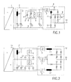
- Fig. 1 shows a line converter or 1st converter (1), the DC side via a DC link (2) with a Drive converter or 2nd converter (8) electrical connected is.
- the DC link (2) has between one positive pole or a positive pole plate (P) and one negative pole or a negative pole plate (N) a filter for damping DC link harmonics from a Series connection of a filter choke (LF) and one Filter capacitor (CF) on; further DC link capacitors or capacitors (C1, C2, C3), the capacitors (C2, C3) each having a reversible one Short-circuit current limiters (3) are connected in series.
- the Reversible short-circuit current limiter (3) has one Parallel connection of one in the reverse direction Short circuit path polarized diode (4), a PTC resistor or PTC thermistor (5) and one Shunt resistor branch (6) on one Surge arrester or varistors (7), see. the Fig. 3 - 5.
- the PTC thermistor (5) and Shunt resistor branch (6) are in the Short-circuit current limiter (3) always available; the diode (4) can be connected in parallel.
- the two converters (1, 8) are two-point converters executed, only for the converter (8) in Fig. 1 two main valve branches with 2 GTO thyristors (T1, T2) as Main valves for an AC phase connected to a AC voltage terminal (10) can be tapped, are shown.
- T1, T2 GTO thyristors
- 6 are similar established main valve branches required.
- Parallel to Each main valve (T1, T2) has a thyristor circuit (9) provided, for the sake of clarity only that for GTO thyristor (T1) is shown. It it goes without saying that the thyristor circuit (9) is also a could have different circuit than that shown.
- the current path of the two main valves (T1, T2) is a choke or di / dt limiting choke (L) via a reversible Short-circuit current limiter (3) with the positive pole (P) of the DC voltage intermediate circuit (2) connected.
- This di / dt limiting choke (L) can be used when using the Short-circuit current limiter (3) according to the invention is very small be held or canceled.
- the reversible short-circuit current limiter (3) in the 2nd Converter (8) can be omitted if reversible Short-circuit current limiter (3) in DC voltage intermediate circuit (2) are provided.
- the reversible Short-circuit current limiter (3) in DC voltage intermediate circuit (2) is omitted if a Reversible short-circuit current limiter (3) in the 2nd converter (8) is provided.
- FIG. 2 shows one of FIG. 1 as the second exemplary embodiment Similar converter circuit, which instead of 1st and 2nd 2-point converters (1, 8) 1st and 2nd 3-point converters (11, 12).
- the same components are the same designated.
- a DC link (2 ') a reversible one for each half of the potential Short-circuit current limiter (3) in series with one Capacitor bank connected, the several in parallel Has capacitors.
- the advantage of this circuit consists in a cost reduction of the protective circuit, because less reversible short-circuit current limiter (3, 3 ') are needed, or in a smaller one System diversification because fewer types of reversible Short-circuit current limiters (3, 3 ') for the Converter range are required.
- a dashed line reversible short-circuit current limiter (3 ') can be provided, which, on the one hand, has a center conductor (13 ') Center path and on the other hand with a Center conductor (13) of the DC link (2 ') is electrically connected. This will make for many Adequate protection is provided by accidents.
- Fig. 3 shows a short-circuit current limiter (3) in which to a PTC thermistor (5) in a 1st or main current path Shunt resistor branch (6) with a series connection from a varistor (7), an ohmic resistor (14) and a choke or inductor (30) connected in parallel is.
- the heater heats up PTC thermistor (5) beyond its response temperature, so that whose resistance increases sharply and limits the current.
- a thermal destruction of the PTC thermistor (5) is caused by a commutation of the short circuit current on the Avoid shunt resistor branch (6).
- Short-circuit current is limited to values for the DC link (2) are harmless.
- the PTC thermistor (5) cools and is ready for use again.
- the PTC thermistor (5) can be a non-blocking PTC thermistor on a metal base with resistance jumps to about 10 times, preferably less than 100 times its cold resistance, or a blocking PTC thermistor based on filled polymers, the resistance jumps to more than 100 times, preferably have more than 10 4 times the cold resistance.
- FIG 3 is essential for the circuit according to FIG Use of a varistor (7), preferably based on of metal oxide, its maximum allowable Continuous operating voltage preferably below that Operating voltage of the DC link (2) lies.
- the ohmic connected in series to the varistor (7) Resistor (14) improves the current limiting behavior the circuit.
- a PTC thermistor (15) blocking or not blocking at the operating voltage according to FIG. 4 can be used instead of the ohmic resistor (14) according to FIG. 3, a PTC thermistor (15) blocking or not blocking at the operating voltage according to FIG. 4 can be used.
- both PTC thermistors (5, 15) have a resistance-temperature characteristic with high jumps in resistance to resistance values that are significantly greater than 100 times, preferably greater than 10 4 times the cold resistance value (blocking PTC thermistor (5)), the overall circuit can have a current-blocking behavior can be achieved. This makes it possible to use the short-circuit current limiter (3) as a protective element in electrical power distribution systems or networks with longer-lasting voltages on the short-circuit current limiter (3).
- the short-circuit current limiter (3) according to FIG. 5 differs from that of Fig. 4 in that in Main current path a non-blocking PTC thermistor (5) with a blocking PTC thermistor (5 ') is connected in series.
- the blocking PTC thermistor (5 ') is designed so that his resistance only after the non-blocking PTC thermistor (5) increased, d. that is, he responds with a time delay, cf. e.g. B. the beginning called CH-A-581 377.
- the PTC thermistor (5 ') relieved electrically and thermally.
- the PTC resistor (15) can have a shunt resistor branch (6) replaced by an ohmic resistor (14) according to FIG. 3 be.
- the circuit shown in FIG. 5 suitable to protect even under overload conditions, whereby the varistor (7) remains blocking.
- the continuous operating voltage of the varistor (7) must be higher than that in this case Operating voltage of the DC link (2) be.
- inductance (30) can improve the Current limiting behavior of the overall circuit reached will.
- Fig. 6 shows the shape of a resistance track non-blocking PTC thermistor (5) in its central Part meandering and symmetrical with respect to one Section plane (A - A ') is formed.
- the starting point is a metal foil, which is created using a usual cutting process, such as. B. water jet cutting or laser cutting, or by a photolithographic Process is structured meandering in the central part.
- a usual cutting process such as. B. water jet cutting or laser cutting, or by a photolithographic Process
- resistance-forming meander tracks (16) in their Longitudinal direction at least simple, but preferably several times through parallel elongated recesses (19) divided, cf. the partial representation a meander track (16) in a section (17).
- Between longitudinally successive cutouts (19) are recess-free cooling islands (18) with a specifiable Longitudinal distance (a) is provided, which increases Nominal current carrying capacity without affecting the dynamic Allow response under short-circuit conditions. With increasing longitudinal distance (a) of the individual recesses (19) from each other, the rated current carrying capacity can continue be improved. Further cooling islands (18 ') are at the ends provided on the meander tracks (16).
- a preferably ferromagnetic metal or a metal alloy can be used as the starting basis for the non-blocking PTC thermistor (5).
- Materials based on nickel, iron or cobalt and their alloys are particularly suitable.
- the particularly high positive temperature coefficient of the specific resistance of these materials compared to nonferromagnetic pure metals has a nonlinear behavior which is favorable for the application, with a maximum in the range of the Curie temperature.
- nonferromagnetic metals such as beryllium or ruthenium, with a temperature coefficient of resistance of> 4 . 10 -3 K -1 can be used.
- the necessary dynamic response behavior of the PTC thermistor (5) under short-circuit conditions is achieved by the formation of a small cross-sectional area of the active part.
- Typical values of the cross-sectional area for a circuit according to FIGS. 1 and 2 are in the range from 0.1 mm 2 to 5 mm 2 , preferably in the range from 0.5 mm 2 to 1.5 mm 2 .
- the cold resistance values at room temperature are in the range of a few 10 m ⁇ - 100 m ⁇ .
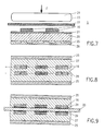
- FIG. 7 shows the basic structure of a non-blocking PTC thermistor (5) that can be operated without ground potential, the resistance path of which is shown in FIG Fig. 6.
- the cooling element (25) has, adjacent to the 1st main surface of the ceramic layer (20), cooling slots (26) through which electrically conductive water (process water) flows, preferably turbulently, during operation.
- One of the 1st main surface opposite the 2nd main surface of the ceramic layer (20) is provided with an electrically insulating heat-conducting layer (21), e.g. B. from oil or a thermal paste based on silicone, covered with a thickness in the range of 10 microns - 100 microns.
- Meander tracks (16) of the resistance body of the PTC thermistor (5), cf. Fig. 6, are between this heat-conducting layer (21) and an electrically insulating, preferably thermally conductive, flexible, high temperature-resistant polymer film (22), for. B.
- a pressure compensation cushion or pressure compensation element (23) can be provided for pressing on, which is acted upon by a force (F) orthogonal to the second main surface of the ceramic layer (20).
- the pressure compensation element (23) z. B. consist of a thin, flexible metal foil which is welded to a closed shell and has a thickness in the range of 0.2 cm - 3 cm.
- the pressure compensation element (23) is filled with a dielectric or electrically conductive fluid (24) with a boiling temperature preferably above 150 ° C. As high-boiling fluids (24) z. B.
- carboxylate esters polyol esters, polymeric dimethylsiloxanes or aliphatic pentaerythritol esters can be used.
- a further heat sink not shown, can be brought into direct contact with the pressure compensation element (23).
- the pressure compensation element (23) achieves, on the one hand, a uniform pressing of the resistance tracks (16) against the ceramic layer (20) and, on the other hand, compensation cooling by convection to protect the resistance tracks (16) from partial overheating.
- the pressure compensation element (23) can then in particular be omitted if the high temperature resistant Polymer film (22) made of silicone elastomer or from a other elastomer material, a thickness in the range of 1.5 mm - 10 mm and a Shore hardness in the range of 10 Shore A - 100 Shore A.
- the resistance or meander tracks (16) of the PTC thermistor (5) are here in a with inorganic, thermally conductive particles, such as. B. from AlN, BN, Al 2 O 3 , filled polymer matrix (27) integrated or embedded.
- the polymer matrix (27) consists of high-temperature thermosets and / or elastomers and / or high-temperature thermoplastics.
- the polymer matrix (27) preferably consists of polyether ether ketones (PEEK) and / or polyether imides (PEI) and / or polysulfones (PSU) and / or polyether sulfones (PES).
- a bimodally distributed powder that is to say a powder whose particle size or diameter has at least 2 frequency maxima, is preferably used as the filler.
- the elastic properties of the polymer matrix (27) allow good thermal contact with their edge-side metallic heat sinks or cooling elements (25), which are preferably cooled by a mixture of water and glycol.
- At least approximately geometrically congruent resistance or meandering tracks (16) are embedded in the polymer matrix (27), through which an electrical current is conducted in anti-parallel.
- Dashed lines indicate an electrical line (28) which electrically connects the meandering tracks (16) on the end face in such a way that current flows through adjacent meandering tracks (16) in an antiparallel direction.
- the meander tracks (16) When executing a PTC thermistor (5) according to FIG an approx. one or both sides of the meander tracks (16) 1 ⁇ m thick Cr / Ni layer applied as an adhesive layer (29).
- the meander tracks (16) are in electrical and thermal conductive contact with a Ceramic layer (20), two meandering tracks (16) each at least approximately geometrically congruent on the Ceramic layer (20) lie opposite. Similar to Fig. 9 are the ceramic layer (20) and the meander tracks (16) of the PTC thermistor (5) embedded in a polymer matrix (27) and by means of cooling elements (25) on the edge, preferably by a mixture of water and glycol, cooled.
Landscapes
- Engineering & Computer Science (AREA)
- Power Engineering (AREA)
- Microelectronics & Electronic Packaging (AREA)
- Emergency Protection Circuit Devices (AREA)
- Thermistors And Varistors (AREA)
- Control Of Eletrric Generators (AREA)
- Rectifiers (AREA)
Description
- Fig. 1
- eine 2Punkt-Stromrichterschaltung mit einem Antriebsstromrichter, der über einen Gleichspannungszwischenkreis mit einem Netzstromrichter verbunden ist, wobei im Kurzschlußpfad von Kondensatoren des Gleichspannungszwischenkreises ein reversibler Strombegrenzer angeordnet ist,
- Fig. 2
- eine Stromrichterschaltung gemäß Fig. 1 mit 3Punkt-Stromrichtern,
- Fig. 3 - 5
- unterschiedliche Strombegrenzerschaltungen mit Kaltleitern, Varistoren und Induktivitäten,
- Fig. 6
- eine konstruktives Ausführungsbeispiel der Widerstandsbahn eines Kaltleiters einer Strombegrenzerschaltung gemäß den Fig. 3 - 5,
- Fig. 7
- den Prinzipaufbau eines erdpotentialfrei betreibbaren Kaltleiters mit Brauchwasserkühlung für große elektrische Leistungen sowie
- Fig. 8 und 9
- den Prinzipaufbau von besonders niederinduktiven Kaltleitern.
- 1, 11
- Netzstromrichter, 1. Stromrichter
- 2, 2'
- Gleichspannungszwischenkreise
- 3, 3'
- Kurzschlußstrombegrenzer, Strombegrenzer
- 4
- Diode
- 5, 5', 15
- Kaltleiter, PTC-Widerstände
- 6
- Nebenschlußwiderstandszweig mit Varistor 7
- 7
- Varistor, Überspannungsableiter
- 8, 12
- Antriebsstromrichter, 2. Stromrichter
- 9
- Thyristorbeschaltung von T1, T2
- 10
- Wechselspannungsklemme von 8
- 13, 13'
- Mittelpunktleiter
- 14
- ohmscher Widerstand
- 16
- Mäanderbahn von 5, Widerstandsbahn aus einem Kaltleiterwerkstoff
- 17
- Ausschnitt von 16
- 18, 18'
- Kühlinseln, Kühlstege
- 19
- Aussparungen in 16
- 20
- Isolation, Keramikschicht
- 21
- Wärmeleitschichten
- 22
- hochtemperaturbeständige Polymerfolie
- 23
- Druckausgleichelement, Druckausgleichkissen
- 24
- dielektrisches Fluid
- 25
- Kühlelement
- 26
- Kühlschlitze in 25
- 27
- gefüllte Polymermatrix
- 28
- elektrische Leitung
- 29
- Chrom-Nickelschicht, Haftschicht
- 30
- Induktivität, Drossel
- a
- Längsabstand von 19
- A - A'
- Schnittebene in Fig. 6
- B - B'
- Schnittebene in Fig. 6, senkrecht zu A - A'
- C1, C2, C3
- Zwischenkreiskondensatoren
- CF
- Filterkondensator
- F
- Kraft
- L, L1, L2
- Drosseln, di/dt-Begrenzungsdrosseln
- LF
- Filterdrossel
- N
- negativer Pol, negative Polplatte
- P
- positiver Pol, positive Polplatte
- T1, T2
- GTO-Thyristoren
Claims (11)
- Reversibler Überstrombegrenzer (3)dadurch gekennzeichnet,a) mit mindestens einem Kaltleiter (5, 5') in einem 1. Stromzweig,b) mit mindestens einem Varistor (7) in einem zum 1. Stromzweig elektrisch parallelgeschalteten 2. Stromzweig (6),c) daß in dem 2. Stromzweig (6) in Reihenschaltung zu dem mindestens einen Varistor (7) ein ohmscher Widerstand (14) geschaltet ist.
- Reversibler Überstrombegrenzer (3)dadurch gekennzeichnet,a) mit mindestens einem Kaltleiter (5, 5') in einem 1. Stromzweig,b) mit mindestens einem Varistor (7) in einem zum 1. Stromzweig elektrisch parallelgeschalteten 2. Stromzweig (6),c) daß in dem 2. Stromzweig (6) in Reihenschaltung zu dem mindestens einen Varistor (7) ein Kaltleiter (15) geschaltet ist, der derart bemessen ist, daß ein Überstrom innerhalb von 10 µs auf einen Stromwert begrenzt wird, welcher unterhalb der Zerstörungsgrenze von passiven Komponenten liegt.
- Reversibler Überstrombegrenzer (3) nach Anspruch 1 oder 2, dadurch gekennzeichnet, daß die Reihenschaltung in dem 2. Stromzweig (6) eine Induktivität (30) aufweist.
- Reversibler Überstrombegrenzer (3) nach einem der vorhergehenden Ansprüche, dadurch gekennzeichnet,a) daß der 1. Stromzweig wenigstens 2 in Reihe geschaltete Kaltleiter (5, 5') aufweist,b) wovon wenigstens ein 1. Kaltleiter (5) beim Erhitzen Widerstandsprünge auf weniger als das 100fache seines Kaltwiderstandes aufweist, undc) wovon wenigstens ein 2. Kaltleiter (5') beim Erhitzen Widerstandsprünge auf mehr als das 100fache,d) insbesondere auf mehr als das 104fache seines Kaltwiderstandes aufweist.
- Reversibler Überstrombegrenzer (3) nach einem der vorhergehenden Ansprüche, dadurch gekennzeichnet, daß in einem zu dem 1. Stromzweig parallelgeschalteten 3. Stromzweig eine Diode (4) in Sperrichtung eines Kurzschlußpfades geschaltet ist.
- Reversibler Überstrombegrenzer (3) nach einem der vorhergehenden Ansprüche, dadurch gekennzeichnet,a) daß eine 1. Hauptfläche des mindestens einen Kaltleiters (5, 5') über eine elektrisch isolierende, gut wärmeleitende Wärmeleitschicht (21) mit einer 1. Hauptfläche einer Keramikschicht (20) in gut wärmeleitender Verbindung steht,b) daß eine der 1. Hauptfläche gegenüberliegende 2. Hauptfläche der Keramikschicht (20) mit einem Kühlelement (25) in gut wärmeleitender Verbindung steht undc) daß eine der 1. Hauptfläche gegenüberliegende 2. Hauptfläche der Widerstandsbahn (16) mit einer Polymerfolie (22) aus Silikonelastomer oder aus einem anderen Elastomerwerkstoff in Druckverbindung steht.
- Reversibler Überstrombegrenzer nach Anspruch 6, dadurch gekennzeichnet,a) daß die Polymerfolie (22) eine Dicke im Bereich von 1,5 mm - 10 mm undb) eine Shorehärte im Bereich von 10 Shore A - 100 Shore A aufweist.
- Reversibler Überstrombegrenzer (3) nach Anspruch 6 oder 7, dadurch gekennzeichnet, daß die Wärmeleitschicht (21) eine Wärmeleitpaste auf Silikonbasis ist und eine Dicke im Bereich von 10 um - 100 um aufweist.
- Reversibler Überstrombegrenzer nach einem der Ansprüche 6 bis 8, dadurch gekennzeichnet,a) daß die Polymerfolie (22) mit einem Druckausgleichelement (23) in Druckverbindung steht,b) insbesondere, daß das Druckausgleichelement (23) aus einer Metallfolie besteht, die eine geschlossene Hülle bildet, welche mit einem dielektrischen oder elektrisch leitfähigen Fluid (24) gefüllt ist, das eine Siedetemperatur über 150 °C hat.
- Reversibler Überstrombegrenzer (3) nach einem der vorhergehenden Ansprüche, dadurch gekennzeichnet,a) daß der mindestens eine Kaltleiter (5, 5') mindestens eine Widerstandsbahn (16) aus einem Kaltleiterwerkstoff aufweist,b) welche in eine Polymermatrix (27) eingebettet ist undc) über diese mit mindestens einem Kühlelement (25) in thermisch leitender Verbindung steht,d) daß wenigstens 2 voneinander beabstandete und wenigstens annähernd geometrisch deckungsgleiche Widerstandsbahnen (16) in zwei übereinanderliegenden Ebenen in die Polymermatrix (27) so eingebettet sind, daß sich die wenigstens annähernd geometrisch deckungsgleichen Teile der Widerstandsbahnen (16) gegenüberliegen unde) daß die Widerstandsbahnen (16) elektrisch so miteinander verbunden sind, daß im Betrieb einander gegenüberliegende Widerstandsbahnen (16) von einem Strom in antiparalleler Richtung durchflossen werden,f) insbesondere, daß die Widerstandsbahn (16) mehrfach durch zueinander parallele Aussparungen (19) unterteilt ist.
- Reversibler Überstrombegrenzer nach Anspruch 10, dadurch gekennzeichnet,a) daß zwischen den gegenüberliegenden Widerstandsbahnen (16) eine Keramikschicht (20) vorgesehen ist undb) daß diese Widerstandsbahnen (16) über eine Metallschicht (29) mit der Keramikschicht (20) in thermisch leitender Verbindung stehen,c) insbesondere, daß diese Metallschicht (29) eine Cr/Ni-Schicht ist.
Applications Claiming Priority (2)
| Application Number | Priority Date | Filing Date | Title |
|---|---|---|---|
| DE4441279 | 1994-11-19 | ||
| DE4441279A DE4441279C1 (de) | 1994-11-19 | 1994-11-19 | Vorrichtung zur Strombegrenzung |
Publications (2)
| Publication Number | Publication Date |
|---|---|
| EP0713228A1 EP0713228A1 (de) | 1996-05-22 |
| EP0713228B1 true EP0713228B1 (de) | 1998-08-26 |
Family
ID=6533696
Family Applications (1)
| Application Number | Title | Priority Date | Filing Date |
|---|---|---|---|
| EP95810681A Expired - Lifetime EP0713228B1 (de) | 1994-11-19 | 1995-10-31 | Vorrichtung zur Strombegrenzung |
Country Status (7)
| Country | Link |
|---|---|
| US (1) | US5796568A (de) |
| EP (1) | EP0713228B1 (de) |
| JP (1) | JPH08214448A (de) |
| AT (1) | ATE170326T1 (de) |
| DE (1) | DE4441279C1 (de) |
| DK (1) | DK0713228T3 (de) |
| ES (1) | ES2123937T3 (de) |
Cited By (1)
| Publication number | Priority date | Publication date | Assignee | Title |
|---|---|---|---|---|
| DE102008019919A1 (de) * | 2008-04-21 | 2009-10-22 | BSH Bosch und Siemens Hausgeräte GmbH | Schaltungsanordnung zum Betreiben einer Türverschlusseinrichtung und entsprechendes Verfahren |
Families Citing this family (63)
| Publication number | Priority date | Publication date | Assignee | Title |
|---|---|---|---|---|
| DE4441279C1 (de) * | 1994-11-19 | 1995-09-21 | Abb Management Ag | Vorrichtung zur Strombegrenzung |
| DE4441280C2 (de) * | 1994-11-19 | 1998-08-27 | Asea Brown Boveri | Kaltleiter und Vorrichtung zur Strombegrenzung mit mindestens einem Kaltleiter |
| DE19634424C2 (de) * | 1996-08-26 | 1998-07-02 | Abb Research Ltd | Verfahren zur Herstellung eines Strombegrenzers mit einem Hochtemperatursupraleiter |
| DE19641727A1 (de) * | 1996-10-10 | 1998-04-16 | Abb Research Ltd | Kaltleiter |
| DE19648381A1 (de) * | 1996-11-22 | 1998-06-04 | Abb Research Ltd | Vorrichtung zur Strombegrenzung |
| US7106570B2 (en) | 1997-04-08 | 2006-09-12 | Xzy Altenuators, Llc | Pathway arrangement |
| US7336467B2 (en) | 2000-10-17 | 2008-02-26 | X2Y Attenuators, Llc | Energy pathway arrangement |
| US6606011B2 (en) | 1998-04-07 | 2003-08-12 | X2Y Attenuators, Llc | Energy conditioning circuit assembly |
| US6650525B2 (en) | 1997-04-08 | 2003-11-18 | X2Y Attenuators, Llc | Component carrier |
| US6603646B2 (en) | 1997-04-08 | 2003-08-05 | X2Y Attenuators, Llc | Multi-functional energy conditioner |
| US7110227B2 (en) | 1997-04-08 | 2006-09-19 | X2Y Attenuators, Llc | Universial energy conditioning interposer with circuit architecture |
| US7321485B2 (en) | 1997-04-08 | 2008-01-22 | X2Y Attenuators, Llc | Arrangement for energy conditioning |
| US20020079116A1 (en) | 2000-10-17 | 2002-06-27 | X2Y Attenuators, Llc | Amalgam of shielding and shielded energy pathways and other elements for single or multiple circuitries with common reference node |
| US6018448A (en) | 1997-04-08 | 2000-01-25 | X2Y Attenuators, L.L.C. | Paired multi-layered dielectric independent passive component architecture resulting in differential and common mode filtering with surge protection in one integrated package |
| US7336468B2 (en) | 1997-04-08 | 2008-02-26 | X2Y Attenuators, Llc | Arrangement for energy conditioning |
| US7301748B2 (en) | 1997-04-08 | 2007-11-27 | Anthony Anthony A | Universal energy conditioning interposer with circuit architecture |
| US20030161086A1 (en) | 2000-07-18 | 2003-08-28 | X2Y Attenuators, Llc | Paired multi-layered dielectric independent passive component architecture resulting in differential and common mode filtering with surge protection in one integrated package |
| US7042703B2 (en) | 2000-03-22 | 2006-05-09 | X2Y Attenuators, Llc | Energy conditioning structure |
| US6894884B2 (en) | 1997-04-08 | 2005-05-17 | Xzy Attenuators, Llc | Offset pathway arrangements for energy conditioning |
| US7274549B2 (en) | 2000-12-15 | 2007-09-25 | X2Y Attenuators, Llc | Energy pathway arrangements for energy conditioning |
| US9054094B2 (en) | 1997-04-08 | 2015-06-09 | X2Y Attenuators, Llc | Energy conditioning circuit arrangement for integrated circuit |
| US7110235B2 (en) | 1997-04-08 | 2006-09-19 | Xzy Altenuators, Llc | Arrangement for energy conditioning |
| DE19736904A1 (de) * | 1997-08-25 | 1999-03-04 | Asea Brown Boveri | Stromrichterschaltungsanordnung |
| DE19758332B4 (de) * | 1997-09-03 | 2005-05-25 | Elan Schaltelemente Gmbh & Co. Kg | Überstromschutzschaltung für einen Sicherheitsrelaisbaustein |
| JPH11274001A (ja) * | 1998-01-19 | 1999-10-08 | Hitachi Ltd | 電力貯蔵装置及びこれを用いた電力変換装置 |
| DE19808025A1 (de) * | 1998-02-26 | 1999-09-02 | Abb Research Ltd | Verfahren zur Herstellung einer Kaltleiteranordnung sowie Verwendung der Kaltleiteranordnung als Strombegrenzer |
| DE19810981A1 (de) * | 1998-03-13 | 1999-09-16 | Abb Research Ltd | Schalter mit PTC-Element zur verbesserten Strombegrenzung und Lichtbogenlöschung |
| US7427816B2 (en) | 1998-04-07 | 2008-09-23 | X2Y Attenuators, Llc | Component carrier |
| JP2003526195A (ja) | 1998-04-07 | 2003-09-02 | エクストゥーワイ、アテニュエイタズ、エル、エル、シー | 部品キャリア |
| JP2000022263A (ja) * | 1998-06-29 | 2000-01-21 | Murata Mfg Co Ltd | 半導体レーザ駆動回路および半導体レーザ装置 |
| JP4284478B2 (ja) * | 1998-12-28 | 2009-06-24 | 株式会社安川電機 | インバータ装置 |
| US6157528A (en) | 1999-01-28 | 2000-12-05 | X2Y Attenuators, L.L.C. | Polymer fuse and filter apparatus |
| US6157286A (en) | 1999-04-05 | 2000-12-05 | General Electric Company | High voltage current limiting device |
| DE19931055A1 (de) * | 1999-07-06 | 2001-01-18 | Epcos Ag | Schutzvorrichtung zur Vermeidung der Überlastung von Kondensatoren mit hochfrequenten Spannungen |
| JP2001118731A (ja) * | 1999-10-19 | 2001-04-27 | Murata Mfg Co Ltd | チップ型複合電子部品およびその製造方法 |
| EP1136073A1 (de) * | 2000-03-22 | 2001-09-26 | N.V. Nutricia | Zusammensetzungen zur Behandlung von Schäden verursacht durch Ischämie/Reperfusion oder oxidativem Stress |
| US7113383B2 (en) | 2000-04-28 | 2006-09-26 | X2Y Attenuators, Llc | Predetermined symmetrically balanced amalgam with complementary paired portions comprising shielding electrodes and shielded electrodes and other predetermined element portions for symmetrically balanced and complementary energy portion conditioning |
| EP1312148A4 (de) | 2000-08-15 | 2009-06-03 | X2Y Attenuators Llc | Elektrodenanordnung zur schaltkreisenergieaufbereitung |
| US7193831B2 (en) | 2000-10-17 | 2007-03-20 | X2Y Attenuators, Llc | Energy pathway arrangement |
| DE10055467A1 (de) * | 2000-11-09 | 2002-05-23 | Bosch Gmbh Robert | Elektrische Maschine, insbesondere Drehstromgenerator |
| DE20101106U1 (de) | 2001-01-22 | 2001-05-10 | David + Baader - DBK - GmbH, 76870 Kandel | Schutzelement in einem elektrischen Schaltkreis |
| US7180718B2 (en) | 2003-01-31 | 2007-02-20 | X2Y Attenuators, Llc | Shielded energy conditioner |
| JP3900104B2 (ja) * | 2003-04-10 | 2007-04-04 | 松下電器産業株式会社 | 静電気対策部品 |
| US7440252B2 (en) | 2003-05-29 | 2008-10-21 | X2Y Attenuators, Llc | Connector related structures including an energy conditioner |
| JP2006528868A (ja) | 2003-07-21 | 2006-12-21 | エックストゥーワイ アテニュエイターズ,エルエルシー | フィルタ組立体 |
| EP1698033A4 (de) | 2003-12-22 | 2010-07-21 | X2Y Attenuators Llc | Intern abgeschirmte energieaufbereitungsvorrichtung |
| US7817397B2 (en) | 2005-03-01 | 2010-10-19 | X2Y Attenuators, Llc | Energy conditioner with tied through electrodes |
| WO2006104613A2 (en) | 2005-03-01 | 2006-10-05 | X2Y Attenuators, Llc | Conditioner with coplanar conductors |
| DE102005009789A1 (de) * | 2005-03-03 | 2006-09-14 | Airbus Deutschland Gmbh | Massnahme zur Erhöhung der Kurzschlussfestigkeit eines Gerätes durch Einführung paralleler Strompfade |
| WO2006099297A2 (en) | 2005-03-14 | 2006-09-21 | X2Y Attenuators, Llc | Conditioner with coplanar conductors |
| US20070029976A1 (en) * | 2005-07-19 | 2007-02-08 | Garcia Jorge L | Method and apparatus for monitoring battery cell temperature |
| KR101390426B1 (ko) | 2006-03-07 | 2014-04-30 | 엑스2와이 어테뉴에이터스, 엘.엘.씨 | 에너지 컨디셔너 구조물들 |
| DE102006033691A1 (de) * | 2006-07-20 | 2008-01-31 | Epcos Ag | Widerstandselement mit PTC-Eigenschaften und hoher elektrischer und thermischer Leitfähigkeit |
| DE102006046040A1 (de) * | 2006-09-28 | 2008-04-03 | Siemens Ag | Thyristorventil einer HGÜ-Anlage |
| DE102008024480A1 (de) * | 2008-05-21 | 2009-12-03 | Epcos Ag | Elektrische Bauelementanordnung |
| KR101275992B1 (ko) * | 2009-01-16 | 2013-06-17 | 에이비비 테크놀로지 아게 | 열공학적으로 폐쇄되는 기계식 스위치들에 의한 중복 스위칭 셀들을 가진 전압원 변환기 |
| US8619395B2 (en) * | 2010-03-12 | 2013-12-31 | Arc Suppression Technologies, Llc | Two terminal arc suppressor |
| CN102930942B (zh) * | 2011-08-12 | 2016-08-17 | 聚鼎科技股份有限公司 | 过电流保护元件 |
| US8687337B2 (en) * | 2011-09-21 | 2014-04-01 | Polytronics Technology Corp. | Over-current protection device |
| DE102014104840B4 (de) * | 2014-04-04 | 2021-12-23 | Jungheinrich Ag | Steuerschaltung für einen von einer Batterie betriebenen Elektromotor |
| US10530240B2 (en) | 2014-04-08 | 2020-01-07 | Siemens Aktiengesellschaft | Method for protecting an electrical modular unit from overcurrent damage |
| CN104578030A (zh) * | 2014-12-19 | 2015-04-29 | 苏州汉克山姆照明科技有限公司 | 户外灯具避雷器 |
| US10895609B2 (en) * | 2019-05-09 | 2021-01-19 | Littelfuse, Inc. | Circuit protection device with PTC element and secondary fuse |
Citations (1)
| Publication number | Priority date | Publication date | Assignee | Title |
|---|---|---|---|---|
| US5296996A (en) * | 1990-02-08 | 1994-03-22 | Asea Brown Boveri Ab | Device for motor and short-circuit protection |
Family Cites Families (13)
| Publication number | Priority date | Publication date | Assignee | Title |
|---|---|---|---|---|
| NL24633C (de) * | 1927-07-25 | 1900-01-01 | ||
| US3654580A (en) * | 1969-03-14 | 1972-04-04 | Sanders Associates Inc | Resistor structure |
| US3887860A (en) * | 1972-11-15 | 1975-06-03 | Eaton Corp | Fuseless inverter |
| US3996447A (en) * | 1974-11-29 | 1976-12-07 | Texas Instruments Incorporated | PTC resistance heater |
| CH581377A5 (de) * | 1975-02-11 | 1976-10-29 | Bbc Brown Boveri & Cie | |
| NL7603997A (nl) * | 1976-04-15 | 1977-10-18 | Philips Nv | Elektrische verhittingsinrichting omvattende een weerstandslichaam uit p.t.c.-materiaal. |
| US4271446A (en) * | 1977-06-27 | 1981-06-02 | Comstock Wilford K | Transient voltage suppression system |
| DE3133485A1 (de) * | 1980-09-15 | 1982-05-06 | Peter 2563 Ipsach Herren | Fluessigkeitsgekuehlte elektrische baugruppe |
| US4583146A (en) * | 1984-10-29 | 1986-04-15 | General Electric Company | Fault current interrupter |
| JP2566556B2 (ja) * | 1986-04-22 | 1996-12-25 | 三菱電機株式会社 | 直流コンデンサの異常検出器 |
| FR2606929B1 (fr) * | 1986-11-14 | 1989-02-10 | Telemecanique Electrique | Dispositif interrupteur pour appareil de protection |
| DE9100865U1 (de) * | 1991-01-25 | 1991-04-18 | Siemens AG, 8000 München | Flüssigkeitsgekühlter Hochlastwiderstand |
| DE4441279C1 (de) * | 1994-11-19 | 1995-09-21 | Abb Management Ag | Vorrichtung zur Strombegrenzung |
-
1994
- 1994-11-19 DE DE4441279A patent/DE4441279C1/de not_active Expired - Lifetime
-
1995
- 1995-10-31 DK DK95810681T patent/DK0713228T3/da active
- 1995-10-31 EP EP95810681A patent/EP0713228B1/de not_active Expired - Lifetime
- 1995-10-31 AT AT95810681T patent/ATE170326T1/de not_active IP Right Cessation
- 1995-10-31 ES ES95810681T patent/ES2123937T3/es not_active Expired - Lifetime
- 1995-11-20 JP JP7301605A patent/JPH08214448A/ja active Pending
-
1997
- 1997-03-20 US US08/822,208 patent/US5796568A/en not_active Expired - Fee Related
Patent Citations (1)
| Publication number | Priority date | Publication date | Assignee | Title |
|---|---|---|---|---|
| US5296996A (en) * | 1990-02-08 | 1994-03-22 | Asea Brown Boveri Ab | Device for motor and short-circuit protection |
Cited By (1)
| Publication number | Priority date | Publication date | Assignee | Title |
|---|---|---|---|---|
| DE102008019919A1 (de) * | 2008-04-21 | 2009-10-22 | BSH Bosch und Siemens Hausgeräte GmbH | Schaltungsanordnung zum Betreiben einer Türverschlusseinrichtung und entsprechendes Verfahren |
Also Published As
| Publication number | Publication date |
|---|---|
| EP0713228A1 (de) | 1996-05-22 |
| DK0713228T3 (da) | 1999-05-25 |
| US5796568A (en) | 1998-08-18 |
| DE4441279C1 (de) | 1995-09-21 |
| ES2123937T3 (es) | 1999-01-16 |
| JPH08214448A (ja) | 1996-08-20 |
| ATE170326T1 (de) | 1998-09-15 |
Similar Documents
| Publication | Publication Date | Title |
|---|---|---|
| DE4441279C1 (de) | Vorrichtung zur Strombegrenzung | |
| EP0713227B1 (de) | Kaltleiter und Vorrichtung zur Strombegrenzung mit mindestens einem Kaltleiter | |
| EP0642199B1 (de) | Schutzschaltung für einen Stromkreis mit einer Kondensatorschaltung | |
| EP0833422B1 (de) | Stromrichterschaltung | |
| DE68922733T2 (de) | Ptc-schaltungsschutzanordnungen. | |
| EP0640995B1 (de) | Elektrisches Widerstandselement und Verwendung dieses Widerstandselementes in einem Strombegrenzer | |
| DE4418050B4 (de) | Hochtemperatursupraleiter und dessen Verwendung | |
| DE19542162C2 (de) | Überstrombegrenzer | |
| DE3146303C2 (de) | Anordnung zum Schutz einer spannungsbegrenzenden Schaltungsanordnung vor Überhitzung durch Überspannung | |
| DE3000394C2 (de) | ||
| DE3303449A1 (de) | Schutzeinrichtung fuer eine supraleitende magnetspulenanordnung | |
| DE19756624A1 (de) | Vorrichtung zur Überstrombegrenzung | |
| US7692911B2 (en) | Arrangement for protection of electronic components | |
| DE3201296A1 (de) | Transistoranordnung | |
| EP4218127B1 (de) | Leistungsbaugruppe für einen mittel- oder hochspannungsumrichter oder für einen leistungselektronischen umrichter eines elektrofahrzeuges | |
| EP1060553B1 (de) | Anordnung sowie verfahren zur strombegrenzung mit einer supraleitenden transformatoranordnung in einem elektrischen schaltkreis | |
| EP1217666A1 (de) | Resistiver Strombegrenzer | |
| EP1069171A2 (de) | Kühlmedium für Hochtemperatursupraleiter | |
| DE2053795A1 (de) | Schutzschaltung fur einen Trans formator | |
| DE2504768A1 (de) | Thyristorsaeule | |
| EP1160884A2 (de) | Hochtemperatursupraleiteranordnung | |
| EP1049238B1 (de) | Elektrische Schaltung insbesondere für einen Frequenzumrichter | |
| JPH09149549A (ja) | 電流制限装置 | |
| DE102021214613A1 (de) | Wärmetauschvorrichtung und daraus bestehender eigensicherer kühlbarer Bremswiderstand | |
| EP0836201A2 (de) | Kaltleiter |
Legal Events
| Date | Code | Title | Description |
|---|---|---|---|
| PUAI | Public reference made under article 153(3) epc to a published international application that has entered the european phase |
Free format text: ORIGINAL CODE: 0009012 |
|
| AK | Designated contracting states |
Kind code of ref document: A1 Designated state(s): AT BE CH DK ES FR GB IT LI NL SE |
|
| 17P | Request for examination filed |
Effective date: 19961014 |
|
| RAP1 | Party data changed (applicant data changed or rights of an application transferred) |
Owner name: ASEA BROWN BOVERI AG |
|
| 17Q | First examination report despatched |
Effective date: 19970307 |
|
| GRAG | Despatch of communication of intention to grant |
Free format text: ORIGINAL CODE: EPIDOS AGRA |
|
| GRAG | Despatch of communication of intention to grant |
Free format text: ORIGINAL CODE: EPIDOS AGRA |
|
| GRAH | Despatch of communication of intention to grant a patent |
Free format text: ORIGINAL CODE: EPIDOS IGRA |
|
| GRAH | Despatch of communication of intention to grant a patent |
Free format text: ORIGINAL CODE: EPIDOS IGRA |
|
| GRAA | (expected) grant |
Free format text: ORIGINAL CODE: 0009210 |
|
| AK | Designated contracting states |
Kind code of ref document: B1 Designated state(s): AT BE CH DK ES FR GB IT LI NL SE |
|
| REF | Corresponds to: |
Ref document number: 170326 Country of ref document: AT Date of ref document: 19980915 Kind code of ref document: T |
|
| REG | Reference to a national code |
Ref country code: CH Ref legal event code: EP |
|
| GBT | Gb: translation of ep patent filed (gb section 77(6)(a)/1977) |
Effective date: 19981117 |
|
| ET | Fr: translation filed | ||
| REG | Reference to a national code |
Ref country code: ES Ref legal event code: FG2A Ref document number: 2123937 Country of ref document: ES Kind code of ref document: T3 |
|
| K2C3 | Correction of patent specification (complete document) published |
Effective date: 19980826 |
|
| REG | Reference to a national code |
Ref country code: DK Ref legal event code: T3 |
|
| PLBE | No opposition filed within time limit |
Free format text: ORIGINAL CODE: 0009261 |
|
| STAA | Information on the status of an ep patent application or granted ep patent |
Free format text: STATUS: NO OPPOSITION FILED WITHIN TIME LIMIT |
|
| 26N | No opposition filed | ||
| REG | Reference to a national code |
Ref country code: GB Ref legal event code: 732E |
|
| REG | Reference to a national code |
Ref country code: FR Ref legal event code: TP |
|
| NLS | Nl: assignments of ep-patents |
Owner name: DAIMLERCHRYSLER AG |
|
| REG | Reference to a national code |
Ref country code: CH Ref legal event code: NV Representative=s name: DAIMLERCHRYSLER AG INTELLECTUAL PROPERTY MANAGEMEN |
|
| REG | Reference to a national code |
Ref country code: CH Ref legal event code: PUE Owner name: ASEA BROWN BOVERI AG TRANSFER- DAIMLERCHRYSLER AG |
|
| REG | Reference to a national code |
Ref country code: GB Ref legal event code: 732E |
|
| NLS | Nl: assignments of ep-patents |
Owner name: DAIMLERCHRYSLER RAIL SYSTEMS GMBH |
|
| REG | Reference to a national code |
Ref country code: CH Ref legal event code: PUE Owner name: DAIMLERCHRYSLER AG TRANSFER- DAIMLERCHRYSLER RAIL Ref country code: CH Ref legal event code: NV Representative=s name: ROTTMANN, ZIMMERMANN + PARTNER AG |
|
| REG | Reference to a national code |
Ref country code: FR Ref legal event code: TP |
|
| REG | Reference to a national code |
Ref country code: GB Ref legal event code: IF02 |
|
| PGFP | Annual fee paid to national office [announced via postgrant information from national office to epo] |
Ref country code: GB Payment date: 20031016 Year of fee payment: 9 Ref country code: FR Payment date: 20031016 Year of fee payment: 9 Ref country code: CH Payment date: 20031016 Year of fee payment: 9 |
|
| PGFP | Annual fee paid to national office [announced via postgrant information from national office to epo] |
Ref country code: SE Payment date: 20031020 Year of fee payment: 9 Ref country code: NL Payment date: 20031020 Year of fee payment: 9 Ref country code: ES Payment date: 20031020 Year of fee payment: 9 |
|
| PGFP | Annual fee paid to national office [announced via postgrant information from national office to epo] |
Ref country code: DK Payment date: 20031021 Year of fee payment: 9 |
|
| PGFP | Annual fee paid to national office [announced via postgrant information from national office to epo] |
Ref country code: AT Payment date: 20031023 Year of fee payment: 9 |
|
| PGFP | Annual fee paid to national office [announced via postgrant information from national office to epo] |
Ref country code: BE Payment date: 20031120 Year of fee payment: 9 |
|
| PG25 | Lapsed in a contracting state [announced via postgrant information from national office to epo] |
Ref country code: LI Free format text: LAPSE BECAUSE OF NON-PAYMENT OF DUE FEES Effective date: 20041031 Ref country code: GB Free format text: LAPSE BECAUSE OF NON-PAYMENT OF DUE FEES Effective date: 20041031 Ref country code: CH Free format text: LAPSE BECAUSE OF NON-PAYMENT OF DUE FEES Effective date: 20041031 Ref country code: BE Free format text: LAPSE BECAUSE OF NON-PAYMENT OF DUE FEES Effective date: 20041031 Ref country code: AT Free format text: LAPSE BECAUSE OF NON-PAYMENT OF DUE FEES Effective date: 20041031 |
|
| PG25 | Lapsed in a contracting state [announced via postgrant information from national office to epo] |
Ref country code: SE Free format text: LAPSE BECAUSE OF NON-PAYMENT OF DUE FEES Effective date: 20041101 Ref country code: DK Free format text: LAPSE BECAUSE OF NON-PAYMENT OF DUE FEES Effective date: 20041101 |
|
| PG25 | Lapsed in a contracting state [announced via postgrant information from national office to epo] |
Ref country code: ES Free format text: LAPSE BECAUSE OF NON-PAYMENT OF DUE FEES Effective date: 20041102 |
|
| BERE | Be: lapsed |
Owner name: *DAIMLERCHRYSLER RAIL SYSTEMS G.M.B.H. Effective date: 20041031 |
|
| PG25 | Lapsed in a contracting state [announced via postgrant information from national office to epo] |
Ref country code: NL Free format text: LAPSE BECAUSE OF NON-PAYMENT OF DUE FEES Effective date: 20050501 |
|
| REG | Reference to a national code |
Ref country code: DK Ref legal event code: EBP |
|
| REG | Reference to a national code |
Ref country code: CH Ref legal event code: PL |
|
| GBPC | Gb: european patent ceased through non-payment of renewal fee |
Effective date: 20041031 |
|
| PG25 | Lapsed in a contracting state [announced via postgrant information from national office to epo] |
Ref country code: FR Free format text: LAPSE BECAUSE OF NON-PAYMENT OF DUE FEES Effective date: 20050630 |
|
| NLV4 | Nl: lapsed or anulled due to non-payment of the annual fee |
Effective date: 20050501 |
|
| EUG | Se: european patent has lapsed | ||
| REG | Reference to a national code |
Ref country code: FR Ref legal event code: ST |
|
| PG25 | Lapsed in a contracting state [announced via postgrant information from national office to epo] |
Ref country code: IT Free format text: LAPSE BECAUSE OF NON-PAYMENT OF DUE FEES;WARNING: LAPSES OF ITALIAN PATENTS WITH EFFECTIVE DATE BEFORE 2007 MAY HAVE OCCURRED AT ANY TIME BEFORE 2007. THE CORRECT EFFECTIVE DATE MAY BE DIFFERENT FROM THE ONE RECORDED. Effective date: 20051031 |
|
| REG | Reference to a national code |
Ref country code: ES Ref legal event code: FD2A Effective date: 20041102 |
|
| BERE | Be: lapsed |
Owner name: *DAIMLERCHRYSLER RAIL SYSTEMS G.M.B.H. Effective date: 20041031 |