EP0713277B1 - Gehäuse mit Vorrichtung zur Halterung von Anschlusskabeln - Google Patents
Gehäuse mit Vorrichtung zur Halterung von Anschlusskabeln Download PDFInfo
- Publication number
- EP0713277B1 EP0713277B1 EP95118119A EP95118119A EP0713277B1 EP 0713277 B1 EP0713277 B1 EP 0713277B1 EP 95118119 A EP95118119 A EP 95118119A EP 95118119 A EP95118119 A EP 95118119A EP 0713277 B1 EP0713277 B1 EP 0713277B1
- Authority
- EP
- European Patent Office
- Prior art keywords
- housing
- angle piece
- housing wall
- cap
- tines
- Prior art date
- Legal status (The legal status is an assumption and is not a legal conclusion. Google has not performed a legal analysis and makes no representation as to the accuracy of the status listed.)
- Expired - Lifetime
Links
- 239000002184 metal Substances 0.000 claims description 5
- 239000000835 fiber Substances 0.000 description 4
- 239000000853 adhesive Substances 0.000 description 2
- 238000005452 bending Methods 0.000 description 1
- 210000001520 comb Anatomy 0.000 description 1
- 238000004891 communication Methods 0.000 description 1
- 230000000295 complement effect Effects 0.000 description 1
- 230000008878 coupling Effects 0.000 description 1
- 238000010168 coupling process Methods 0.000 description 1
- 238000005859 coupling reaction Methods 0.000 description 1
- 238000005516 engineering process Methods 0.000 description 1
- 230000007257 malfunction Effects 0.000 description 1
- 238000004519 manufacturing process Methods 0.000 description 1
- 239000000463 material Substances 0.000 description 1
- 230000003287 optical effect Effects 0.000 description 1
- 239000013307 optical fiber Substances 0.000 description 1
Images

Classifications
-
- H—ELECTRICITY
- H02—GENERATION; CONVERSION OR DISTRIBUTION OF ELECTRIC POWER
- H02G—INSTALLATION OF ELECTRIC CABLES OR LINES, OR OF COMBINED OPTICAL AND ELECTRIC CABLES OR LINES
- H02G3/00—Installations of electric cables or lines or protective tubing therefor in or on buildings, equivalent structures or vehicles
- H02G3/02—Details
- H02G3/08—Distribution boxes; Connection or junction boxes
- H02G3/081—Bases, casings or covers
- H02G3/083—Inlets
-
- H—ELECTRICITY
- H02—GENERATION; CONVERSION OR DISTRIBUTION OF ELECTRIC POWER
- H02G—INSTALLATION OF ELECTRIC CABLES OR LINES, OR OF COMBINED OPTICAL AND ELECTRIC CABLES OR LINES
- H02G3/00—Installations of electric cables or lines or protective tubing therefor in or on buildings, equivalent structures or vehicles
- H02G3/02—Details
- H02G3/08—Distribution boxes; Connection or junction boxes
- H02G3/14—Fastening of cover or lid to box
-
- Y—GENERAL TAGGING OF NEW TECHNOLOGICAL DEVELOPMENTS; GENERAL TAGGING OF CROSS-SECTIONAL TECHNOLOGIES SPANNING OVER SEVERAL SECTIONS OF THE IPC; TECHNICAL SUBJECTS COVERED BY FORMER USPC CROSS-REFERENCE ART COLLECTIONS [XRACs] AND DIGESTS
- Y10—TECHNICAL SUBJECTS COVERED BY FORMER USPC
- Y10S—TECHNICAL SUBJECTS COVERED BY FORMER USPC CROSS-REFERENCE ART COLLECTIONS [XRACs] AND DIGESTS
- Y10S174/00—Electricity: conductors and insulators
- Y10S174/08—Shrinkable tubes
Definitions
- the invention relates to a housing with a device for strain-relieved holder of connecting cables in the preamble of Claim 1 specified design. Housing with such Devices are used particularly in systems of electrical and optical communication technology used.
- DE 40 08 840 C1 describes a housing with a distributor device known for optical fibers, in which the device for strain-relieved holder of the connection cable from several in the housing arranged cable clamps. With each cable clamp a Connection cable by pressing the cable clamp into one corresponding hole in the carrier plate within the housing attached.
- a housing with cable clamp fastening a connecting cable and further, through an opening in the housing Fiber optic lines is described in DE 41 33 372 C2.
- the Fiber optic cables end in plugs that connect to the housing in one Sheet metal bracket attached couplings are connected.
- DE 39 30 781 C2 is another Telecommunications socket known in the outside of the socket housing a cover arrangement consisting of cover caps and plug inserts is provided with respect to the front of the can housing parallel or inclined cable routing permitted.
- a housing with a device for strain relief mounting of Connection cables according to the preamble of claim 1 is from the DE 92 00 154 U1 known. In the case are in the Base plate of punched cutouts (Fig. 2) holding combs with prongs formed to which the connection cable with commercially available Cable ties are attached. The arrangement of the cable strain relief within the housing, however, is often not claimed sufficient housing volume available. Furthermore exists when fixing the connection cable with cable ties the risk of cable constriction, depending on the cable type Malfunctions of equipment housed in the housing being able to lead.
- the invention has for its object a simple one Device for attaching the strain relief to the outside of the housing of connecting cables to create a gentle and mechanical Protected attachment of pressure-sensitive connection cables allowed. This object is achieved with the in claim 1 specified features solved. Refinements of the device are the subclaims and achievable advantages of the description remove.
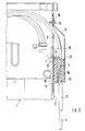
- the housing with 1 and one Housing wall thereof generally designated 2.
- the housing wall 2 can be any part of a housing 1, such as for example around a side or rear wall or also around the Front plate of the frame-shaped housing of a plug-in module.
- the illustrated embodiment of the housing wall 2 has at least one rectangular opening 3 for the passage of Connection cables 4. Instead of a larger opening 3, however also several small, if necessary also round openings are provided will.
- FIG. 1 and 2 show, is in a small parallel distance to longitudinal edge of the rectangular opening 3 a retaining comb arranged.
- This consists of an elbow 5 with an L-shaped Cross-section, which is preferably made of one piece of sheet metal manufactured stamped and bent part.
- the shorter leg 6 of the Elbow 5 has two projecting tabs 7 at the lower end thus secure against rotation in complementary holes 8 in the housing wall 2 intervene that the leg 6 is perpendicular to the housing wall and the longer leg 9 a parallel distance from the housing wall 2 has.
- the long leg 9 is divided into comb-like tines 10 which extend perpendicular to the bending edge of the elbow 5.
- the Prongs 10 are used to fasten each one preferably the opening 3 into the housing 1 leading connecting cable 4 by means of a shrink tube 11.
- the tines have one for this correspondingly suitable length that is a multiple of Cable diameter.
- the tines 10 are free End each with a widening, which the heat shrink tubing 11 with the connecting cables 4 fix non-slip on the holding comb.
- the Elbow 5 can either have the required number of tines 10 have or be designed so that the type reduction maximum required number of tines 10 is kept available.
- the shrink tube attachment of the connecting cable 4 has the Advantage that the latter in the area of the full tine length on the entire scope. Constrictions cannot occur which makes this type of attachment for fiber optic or micro coaxial cables and especially for other pressure-sensitive connecting cables 4 suitable is.
- the shrink sleeves 11 used are longer than the tines 10, often twice as long, making the protruding Hose ends of the connecting cables 4 offer good kink protection.
- connection cable 4 are expediently only during assembly attached to the elbow 5 and this together with the Connection cables 4 loosely inserted into the holes 8 of the housing wall 2.
- the long leg 9 of the elbow 5 with e.g. out a foamed plastic or another suitable Material existing elastic cushion 12 underlaid the one forms soft pad and, for example, self-adhesive on the Housing wall 2 is attached.
- Angle piece 5 and housing wall opening are e.g. as Stamped and bent part, cap 13 made of sheet metal, can be covered, which is largely open at the end of the cap. That at the The cable end of the open cable end has the bottom edge of the Side walls 14 each have a hook 15 with which the cap 13 at First mount in corresponding slots 16 in the housing wall 2 hooked in and then tilted until the other closed cap end 17 provided tab 18 on the Housing wall 2 abuts and on this e.g. with just one screw 19, which can be a so-called sheet metal screw, is releasably attached.
- the elbow 5 is also Holding comb and shrink-tube-fixed connecting cables 4 between elastic cushion 12 and cap lid 20 held.
- cap 13 with higher side walls 14 train and at the rear end of the cap lid 20 inside provide the same elastic pillow 21 as the underlying, so that the retaining comb with attached connecting cables 4 between two elastic cushions 12, 21 is fixed. That e.g. Likewise self-adhesive cushions 21 allow the compensation of large permissible manufacturing tolerances and also the attachment of Connection cables 4 with different diameters.
- the elastic pillows 12, 21 are extremely inexpensive in Commercially available yard goods can be produced.
- the yard goods will Usually supplied in rolls, of which the pieces required just be separated.
Landscapes
- Engineering & Computer Science (AREA)
- Architecture (AREA)
- Civil Engineering (AREA)
- Structural Engineering (AREA)
- Installation Of Indoor Wiring (AREA)
- Cable Accessories (AREA)
Description
- Fig. 1
- einen Ausschnitt einer Gehäusewand mit zugentlastet gehaltenem Anschlußkabel, während der Montage einer Kappe, in perspektivischer Ansicht;
- Fig. 2
- einen Ausschnitt eines Gehäuses mit zugentlastet gehaltenem Anschlußkabel und der an einer Gehäusewand befestigten Kappe, teilweise geschnitten, in einer Seitenansicht.
Claims (10)
- Gehäuse mit Vorrichtung zur zugentlasteten Halterung von Anschlußkabeln, die durch wenigstens eine Öffnung in das Gehäuse einführbar und an Zinken eines Haltekammes befestigbar sind, dadurch gekennzeichnet, daß der Haltekamm aus einem lose in Löcher (8) der Gehäusewand (2) eingesetzten Winkelstück (5) besteht, das mittels einer an der Gehäusewand (2) abnehmbar befestigten Kappe (13) fixiert ist und daß die Zinken (10) eine zur Schrumpfschlauch-Befestigung der Anschlußkabel (4) geeignete Länge haben.
- Gehäuse mit Vorrichtung nach Anspruch 1, dadurch gekennzeichnet, daß das Winkelstück (5) mit einem elastischen Kissen (12) unterlegt ist.
- Gehäuse mit Vorrichtung nach Anspruch 1, dadurch gekennzeichnet, daß die Kappe (13) ein auf das Winkelstück (5) drückendes elastisches Kissen (21) enthält.
- Gehäuse mit Vorrichtunq nach Anspruch 1. dadurch Querschnitt mit zwei Schenkeln (6, 9) hat, von denen der kürzere Schenkel (6) senkrecht auf der Gehäusewand (2) steht und der längere Schenkel (9) sich in parallelem Abstand zur Gehäusewand (2) erstreckt.
- Gehäuse mit Vorrichtung nach Anspruch 4, dadurch gekennzeichnet, daß der auf der Gehäusewand (2) stehende Schenkel (6) des Winkelstücks (5) am unteren Ende zwei in die Löcher (8) der Gehäusewand (2) eingreifende Lappen (7) hat.
- Gehäuse mit Vorrichtung nach Anspruch 4, dadurch gekennzeichnet, daß der längere Schenkel (9) des Winkelstücks (5) sich senkrecht zur Biegekante des Winkelstücks (5) erstreckende Zinken (10) aufweist.
- Gehäuse mit Vorrichtung nach Anspruch 1, dadurch gekennzeichnet, daß die Kappe (13) an der Kabelzuführungsseite offen ist und an diesem Kappenende zwei Haken (15) hat, mit denen sie in passende Schlitze (16) der Gehäusewand (2) eingehängt und dabei das Winkelstück (5) sowie die Öffnung (3) abdeckend mit einer an der Kappe (13) vorgesehenen Lasche (18) an der Gehäusewand (2) befestigt ist.
- Gehäuse mit Vorrichtung nach Anspruch 7, dadurch gekennzeichnet, daß die Lasche (18) mittels einer Schraube (19) an der Gehäusewand (2) befestigt ist.
- Gehäuse mit Vorrichtung nach Anspruch 7, dadurch gekennzeichnet, daß Winkelstück (5) und Kappe (13) jeweils einstückig aus Blech gefertigte Stanzbiegeteile sind.
- Gehäuse mit Vorrichtung nach Anspruch 2 oder 3, dadurch gekennzeichnet, daß die elastischen Kissen (12, 21) aus einem aufgeschäumten Kunststoff bestehen.
Applications Claiming Priority (2)
| Application Number | Priority Date | Filing Date | Title |
|---|---|---|---|
| DE4441230A DE4441230A1 (de) | 1994-11-19 | 1994-11-19 | Gehäuse mit Vorrichtung zur Halterung von Anschlußkabeln |
| DE4441230 | 1994-11-19 |
Publications (2)
| Publication Number | Publication Date |
|---|---|
| EP0713277A1 EP0713277A1 (de) | 1996-05-22 |
| EP0713277B1 true EP0713277B1 (de) | 1998-09-30 |
Family
ID=6533661
Family Applications (1)
| Application Number | Title | Priority Date | Filing Date |
|---|---|---|---|
| EP95118119A Expired - Lifetime EP0713277B1 (de) | 1994-11-19 | 1995-11-17 | Gehäuse mit Vorrichtung zur Halterung von Anschlusskabeln |
Country Status (3)
| Country | Link |
|---|---|
| US (1) | US5693908A (de) |
| EP (1) | EP0713277B1 (de) |
| DE (2) | DE4441230A1 (de) |
Cited By (1)
| Publication number | Priority date | Publication date | Assignee | Title |
|---|---|---|---|---|
| CN104221236A (zh) * | 2012-05-03 | 2014-12-17 | 威德米勒界面有限公司及两合公司 | 穿引壳体 |
Families Citing this family (30)
| Publication number | Priority date | Publication date | Assignee | Title |
|---|---|---|---|---|
| DE19601518B4 (de) | 1996-01-17 | 2016-05-12 | Wabco Gmbh | Gehäuse für eine elektrische Baugruppe |
| JPH10134898A (ja) * | 1996-10-28 | 1998-05-22 | Asmo Co Ltd | リード線の引出構造 |
| DE19709558C2 (de) * | 1997-03-07 | 1999-06-10 | Rolec Gehaeusesysteme Rose & R | Vorrichtung zum Verschließen und Abdichten von Kabeldurchführungsdurchbrüchen für Kabel mit vormontierten Steckern |
| JPH11234874A (ja) * | 1998-02-20 | 1999-08-27 | Nec Corp | コンピュータデスク装置 |
| US6162989A (en) * | 1998-06-22 | 2000-12-19 | Honeywell Inc | Cable entry shield (EMI-RFI) for electronic units |
| CA2265175A1 (en) * | 1999-03-11 | 2000-09-11 | Newbridge Networks Corporation | A latching device for a circuit pack |
| USD449584S1 (en) | 2000-04-10 | 2001-10-23 | Thomas & Betts International, Inc. | Wall plate for directional couplers |
| FR2813715B1 (fr) * | 2000-09-01 | 2002-12-20 | France Telecom | Dispositif de precablage dans une installation de cablage et procede de mise en oeuvre |
| US6768057B2 (en) * | 2001-03-12 | 2004-07-27 | Ibc Corporation | Connector for flexible electrical conduit |
| DE10304905B3 (de) * | 2003-02-06 | 2004-05-13 | Siemens Ag | Abdeckung für ein elektronisches Gerät |
| DE10327043A1 (de) * | 2003-06-16 | 2005-01-05 | BSH Bosch und Siemens Hausgeräte GmbH | Zugentlastung für ein Elektrokabel |
| US6812402B1 (en) * | 2003-09-24 | 2004-11-02 | Siemens Building Technologies, Inc. | Apparatus for securing electrical wiring to a device |
| KR101053850B1 (ko) * | 2004-06-08 | 2011-08-03 | 삼성전자주식회사 | 디스플레이장치 |
| JP4666596B2 (ja) * | 2004-07-15 | 2011-04-06 | 株式会社リコー | 外付け装置、および電気電子機器 |
| EP1679766A1 (de) * | 2005-01-10 | 2006-07-12 | 3M Innovative Properties Company | Drahtführungsplatte und Zusammenbau sowie ein Telekommunikationsmodul mit wenigtens einer Drahtführungsplatte |
| JP2010000255A (ja) * | 2008-06-20 | 2010-01-07 | Fujitsu Component Ltd | 脈拍検出装置およびその製造方法並びにコネクタユニット |
| GB2462595B (en) * | 2008-08-11 | 2011-05-18 | Raymond Brewer | Junction box |
| US8511630B2 (en) * | 2008-10-10 | 2013-08-20 | Simplexgrinnell Lp | Emergency notification appliance mounting bracket |
| DE102009016229A1 (de) * | 2009-04-03 | 2010-10-21 | Siemens Aktiengesellschaft | Einrichtung zur Kabelführung |
| WO2011033553A1 (ja) * | 2009-09-15 | 2011-03-24 | 三菱電機株式会社 | フラットケーブル挿通口の蓋構造 |
| TWI469710B (zh) * | 2010-02-04 | 2015-01-11 | Hon Hai Prec Ind Co Ltd | 電子設備殼體 |
| RU2447559C1 (ru) * | 2010-12-07 | 2012-04-10 | Общество с ограниченной ответственностью "Би Питрон" | Способ формирования кабельных трасс |
| JP5542783B2 (ja) * | 2011-11-15 | 2014-07-09 | シャープ株式会社 | 電気ケーブル接続装置、及び画像形成装置 |
| KR101821907B1 (ko) * | 2013-08-23 | 2018-01-24 | 미쓰비시덴키 가부시키가이샤 | 케이블 덕트 내장형 전기 기기 |
| US20170009646A1 (en) * | 2014-01-31 | 2017-01-12 | Makita Corporation | Portable work machine |
| FI12016U1 (fi) * | 2018-03-22 | 2018-04-06 | Camman Oy | Asennusteline putkistolinjoihin |
| CN113056127B (zh) * | 2019-12-27 | 2024-12-27 | 鸿富锦精密电子(郑州)有限公司 | 壳体组件及具有该壳体组件的电子装置 |
| IT202000000604A1 (it) * | 2020-01-15 | 2021-07-15 | Carel Ind Spa | Dispositivo fermacavi e contenitore per un dispositivo elettronico, che lo comprende |
| US12495697B2 (en) * | 2021-08-06 | 2025-12-09 | Bi-Search International, Inc. | System and method for constructing an organic light emitting diode (OLED) display for outdoor use |
| US12604444B2 (en) * | 2024-04-26 | 2026-04-14 | Dell Products L.P. | Electromagnetic interference protection door for data processing systems |
Family Cites Families (9)
| Publication number | Priority date | Publication date | Assignee | Title |
|---|---|---|---|---|
| US4495680A (en) * | 1982-02-17 | 1985-01-29 | Appleton Mills | Method and apparatus for forming a helical wound substrate composed solely of longitudinal yarns |
| DE8417683U1 (de) * | 1984-06-09 | 1984-09-13 | Licentia Patent-Verwaltungs-Gmbh, 6000 Frankfurt | Zugentlastendes Klemmstück aus Kunststoff zur Befestigung eines Zuleitungskabels in einer Gehäusewandöffnung |
| US4816619A (en) * | 1988-06-29 | 1989-03-28 | Ncr Corporation | Passive strain relief apparatus |
| DE3930781C2 (de) * | 1989-09-14 | 1994-08-04 | Berker Geb | Abdeckanordnung für Telekommunikations-Steckdosen zum Erhalt senkrechter oder schräger Leitungsführungen |
| DE4008840C1 (en) | 1990-03-20 | 1991-08-29 | Rittal-Werk Rudolf Loh Gmbh & Co Kg, 6348 Herborn, De | Optical fibre splice distributor - has chambers on carrier plate having bowed fixing flaps on narrow side |
| DE4133372C2 (de) * | 1991-10-05 | 1994-04-07 | Krone Ag | Lichtwellenleiter-Verteilereinrichtung |
| FR2683679B1 (fr) * | 1991-11-12 | 1994-02-04 | Aerospatiale Ste Nationale Indle | Procede pour connecter le blindage d'au moins un cable electrique blinde a un conducteur electrique de liaison, et connexion obtenue par mise en óoeuvre de ce procede. |
| DE9200154U1 (de) * | 1992-01-09 | 1992-03-05 | Quante AG, 5600 Wuppertal | Rangiervorrichtung für Lichtleitkabel |
| EP0699355B1 (de) * | 1993-04-26 | 2000-10-18 | Berg Electronics Manufacturing B.V. | Verdrahtungsadapter zum anschliessen eines kabels |
-
1994
- 1994-11-19 DE DE4441230A patent/DE4441230A1/de not_active Withdrawn
-
1995
- 1995-11-15 US US08/558,813 patent/US5693908A/en not_active Expired - Fee Related
- 1995-11-17 DE DE59503775T patent/DE59503775D1/de not_active Expired - Fee Related
- 1995-11-17 EP EP95118119A patent/EP0713277B1/de not_active Expired - Lifetime
Cited By (1)
| Publication number | Priority date | Publication date | Assignee | Title |
|---|---|---|---|---|
| CN104221236A (zh) * | 2012-05-03 | 2014-12-17 | 威德米勒界面有限公司及两合公司 | 穿引壳体 |
Also Published As
| Publication number | Publication date |
|---|---|
| EP0713277A1 (de) | 1996-05-22 |
| DE59503775D1 (de) | 1998-11-05 |
| DE4441230A1 (de) | 1996-05-23 |
| US5693908A (en) | 1997-12-02 |
Similar Documents
| Publication | Publication Date | Title |
|---|---|---|
| DE4441230A1 (de) | Gehäuse mit Vorrichtung zur Halterung von Anschlußkabeln | |
| EP1317025B1 (de) | Belastbare Steckeranordnung für Datenkabel, insbesondere RJ-45-Verbinder | |
| DE60100320T2 (de) | Aufbau verriegelbarer Verbinder | |
| WO2009024195A1 (de) | Kabelverbindungseinrichtung und verbindungsvorrichtung mit derartigen kabelverbindungseinrichtungen | |
| DE112011100211T5 (de) | Aufbau zum Fixieren einer elektrischen Anschlussdose | |
| DE60208006T2 (de) | Kabelanschlussvorrichtung | |
| DE69502092T2 (de) | Pressitz zugentlastung | |
| DE102015206864A1 (de) | Abschirmgehäuse | |
| DE9303465U1 (de) | Anschlußvorrichtung für abgeschirmte Kabel | |
| DE69121126T2 (de) | Gerät zum Halten von Kabeln | |
| DE102016112758A1 (de) | Halteteil und verfahren zum befestigen von elektrischen leitungen sowie leitungsanordnng in einem fahrzeug | |
| DE10151208A1 (de) | Flachkabelverbinder | |
| CH681668A5 (de) | ||
| DE69520323T2 (de) | Gehäuse für Verbinderanordnung | |
| DE102018131310A1 (de) | Adaptergehäuse für einen Kontakteinsatz zur Fixierung auf einer Hutschiene | |
| DE9311457U1 (de) | Steckverbinder mit Rastmitteln | |
| DE3516150C2 (de) | Ausziehsicherung für Steckverbindungen | |
| DE102006018295B4 (de) | Basisanordnung und ein Kabelbefestigungselement davon | |
| AT408820B (de) | Datenübertragungs-auslassbausatz | |
| DE2653592C2 (de) | Flachkabel-Anschlußvorrichtung | |
| DE202022101591U1 (de) | Kabelanschlussvorrichtung und damit ausgebildete Einrichtung | |
| DE4419785A1 (de) | Zugentlastungsvorrichtung | |
| DE102025134040A1 (de) | Adapter zum befestigen einer vorrichtung auf einer tragschiene | |
| DE29709848U1 (de) | Vorrichtung zum Aufnehmen und Haltern von Schläuchen | |
| DE102016102098A1 (de) | Verbindungsmodul für die Telekommunikations- und Datentechnik |
Legal Events
| Date | Code | Title | Description |
|---|---|---|---|
| PUAI | Public reference made under article 153(3) epc to a published international application that has entered the european phase |
Free format text: ORIGINAL CODE: 0009012 |
|
| AK | Designated contracting states |
Kind code of ref document: A1 Designated state(s): CH DE ES FR GB IT LI SE |
|
| 17P | Request for examination filed |
Effective date: 19960920 |
|
| GRAG | Despatch of communication of intention to grant |
Free format text: ORIGINAL CODE: EPIDOS AGRA |
|
| 17Q | First examination report despatched |
Effective date: 19970917 |
|
| GRAG | Despatch of communication of intention to grant |
Free format text: ORIGINAL CODE: EPIDOS AGRA |
|
| GRAH | Despatch of communication of intention to grant a patent |
Free format text: ORIGINAL CODE: EPIDOS IGRA |
|
| GRAH | Despatch of communication of intention to grant a patent |
Free format text: ORIGINAL CODE: EPIDOS IGRA |
|
| GRAA | (expected) grant |
Free format text: ORIGINAL CODE: 0009210 |
|
| RAP1 | Party data changed (applicant data changed or rights of an application transferred) |
Owner name: ALCATEL ALSTHOM COMPAGNIE GENERALE D'ELECTRICITE |
|
| AK | Designated contracting states |
Kind code of ref document: B1 Designated state(s): CH DE ES FR GB IT LI SE |
|
| PG25 | Lapsed in a contracting state [announced via postgrant information from national office to epo] |
Ref country code: IT Free format text: LAPSE BECAUSE OF FAILURE TO SUBMIT A TRANSLATION OF THE DESCRIPTION OR TO PAY THE FEE WITHIN THE PRE;WARNING: LAPSES OF ITALIAN PATENTS WITH EFFECTIVE DATE BEFORE 2007 MAY HAVE OCCURRED AT ANY TIME BEFORE 2007. THE CORRECT EFFECTIVE DATE MAY BE DIFFERENT FROM THE ONE RECORDED.SCRIBED TIME-LIMIT Effective date: 19980930 Ref country code: ES Free format text: THE PATENT HAS BEEN ANNULLED BY A DECISION OF A NATIONAL AUTHORITY Effective date: 19980930 |
|
| REG | Reference to a national code |
Ref country code: CH Ref legal event code: EP |
|
| GBT | Gb: translation of ep patent filed (gb section 77(6)(a)/1977) |
Effective date: 19981009 |
|
| REF | Corresponds to: |
Ref document number: 59503775 Country of ref document: DE Date of ref document: 19981105 |
|
| ET | Fr: translation filed | ||
| PG25 | Lapsed in a contracting state [announced via postgrant information from national office to epo] |
Ref country code: SE Free format text: LAPSE BECAUSE OF FAILURE TO SUBMIT A TRANSLATION OF THE DESCRIPTION OR TO PAY THE FEE WITHIN THE PRESCRIBED TIME-LIMIT Effective date: 19981231 |
|
| RAP4 | Party data changed (patent owner data changed or rights of a patent transferred) |
Owner name: ALCATEL |
|
| RAP4 | Party data changed (patent owner data changed or rights of a patent transferred) |
Owner name: ALCATEL |
|
| PLBE | No opposition filed within time limit |
Free format text: ORIGINAL CODE: 0009261 |
|
| STAA | Information on the status of an ep patent application or granted ep patent |
Free format text: STATUS: NO OPPOSITION FILED WITHIN TIME LIMIT |
|
| 26N | No opposition filed | ||
| PG25 | Lapsed in a contracting state [announced via postgrant information from national office to epo] |
Ref country code: LI Free format text: LAPSE BECAUSE OF NON-PAYMENT OF DUE FEES Effective date: 19991130 Ref country code: CH Free format text: LAPSE BECAUSE OF NON-PAYMENT OF DUE FEES Effective date: 19991130 |
|
| REG | Reference to a national code |
Ref country code: CH Ref legal event code: PL |
|
| REG | Reference to a national code |
Ref country code: GB Ref legal event code: IF02 |
|
| PGFP | Annual fee paid to national office [announced via postgrant information from national office to epo] |
Ref country code: GB Payment date: 20031029 Year of fee payment: 9 |
|
| PGFP | Annual fee paid to national office [announced via postgrant information from national office to epo] |
Ref country code: DE Payment date: 20031103 Year of fee payment: 9 |
|
| PGFP | Annual fee paid to national office [announced via postgrant information from national office to epo] |
Ref country code: FR Payment date: 20031107 Year of fee payment: 9 |
|
| PG25 | Lapsed in a contracting state [announced via postgrant information from national office to epo] |
Ref country code: GB Free format text: LAPSE BECAUSE OF NON-PAYMENT OF DUE FEES Effective date: 20041117 |
|
| PG25 | Lapsed in a contracting state [announced via postgrant information from national office to epo] |
Ref country code: DE Free format text: LAPSE BECAUSE OF NON-PAYMENT OF DUE FEES Effective date: 20050601 |
|
| GBPC | Gb: european patent ceased through non-payment of renewal fee |
Effective date: 20041117 |
|
| PG25 | Lapsed in a contracting state [announced via postgrant information from national office to epo] |
Ref country code: FR Free format text: LAPSE BECAUSE OF NON-PAYMENT OF DUE FEES Effective date: 20050729 |
|
| REG | Reference to a national code |
Ref country code: FR Ref legal event code: ST |