EP0713636A2 - Machine agricole pour le travail du sol - Google Patents
Machine agricole pour le travail du sol Download PDFInfo
- Publication number
- EP0713636A2 EP0713636A2 EP95118344A EP95118344A EP0713636A2 EP 0713636 A2 EP0713636 A2 EP 0713636A2 EP 95118344 A EP95118344 A EP 95118344A EP 95118344 A EP95118344 A EP 95118344A EP 0713636 A2 EP0713636 A2 EP 0713636A2
- Authority
- EP
- European Patent Office
- Prior art keywords
- tine
- axle body
- machine according
- tines
- frame
- Prior art date
- Legal status (The legal status is an assumption and is not a legal conclusion. Google has not performed a legal analysis and makes no representation as to the accuracy of the status listed.)
- Granted
Links
Images

Classifications
-
- A—HUMAN NECESSITIES
- A01—AGRICULTURE; FORESTRY; ANIMAL HUSBANDRY; HUNTING; TRAPPING; FISHING
- A01B—SOIL WORKING IN AGRICULTURE OR FORESTRY; PARTS, DETAILS, OR ACCESSORIES OF AGRICULTURAL MACHINES OR IMPLEMENTS, IN GENERAL
- A01B35/00—Other machines for working soil
- A01B35/20—Tools; Details
- A01B35/28—Rotating tools; Mounting rotating tools
-
- A—HUMAN NECESSITIES
- A01—AGRICULTURE; FORESTRY; ANIMAL HUSBANDRY; HUNTING; TRAPPING; FISHING
- A01B—SOIL WORKING IN AGRICULTURE OR FORESTRY; PARTS, DETAILS, OR ACCESSORIES OF AGRICULTURAL MACHINES OR IMPLEMENTS, IN GENERAL
- A01B35/00—Other machines for working soil
- A01B35/16—Other machines for working soil with rotating or circulating non-propelled tools
Definitions
- the invention relates to an agricultural tillage machine with a frame which can be coupled to a towing vehicle and at least two tine rollers which are arranged one behind the other in the direction of travel and are oriented transversely to the direction of travel and passively engage in the ground by tine engagement, the tine rollers meshing with one another and being rotatably mounted on at least one rocker and the rocker is arranged on the frame so as to be pivotable about an axis running transversely to the direction of travel, so that when the rocker is pivoted one of the tine rollers mounted on it is moved upwards and one tine roller is moved downwards.
- Such an agricultural tillage machine is known from FR-A 2 619 667.
- the tine rollers have cylindrical axle bodies, from which tines, which are designed in the manner of spits with relatively small cross sections, project essentially radially.
- the free tine ends are somewhat angled relative to the tine part on the axle body, so that the free ends are located in the direction of rotation of the roller of the respective fastening point on the axle body, which direction is determined by the direction of travel.
- the upper layer of a soil to be worked can be loosened in a satisfactory manner, but the resulting lumps of earth are relatively large, so that the surface of the soil is uneven after processing. For this reason, it is necessary to add additional soil cultivation equipment to the tine rollers in order to shred the pieces of earth and level the ground before, for example, seeds can be introduced into the ground.
- the object of the invention is to provide a tillage machine of the type mentioned, which can loosen and turn the soil into deeper areas with a small overall length and also ensures particularly effective comminution of boulders and the like with good leveling and working through the upper soil layer.
- the tine rollers have an axle body and a plurality of tines fastened to the outer surface of the axle body, the longitudinal axis of which extends outside the circumference of the axle body and the free ends of which in the direction of rotation of the roller of the respective fastening point, which direction is determined by the direction of travel are trailing on the axle beam.
- cultivators or cultivators directly behind the rear tine roller arrange other tools with a similar peeling effect. Since such tillage tools to a large extent throw the detected soil upwards and forwards in the direction of travel of the tillage machine, it can be achieved that soil gripped by the cultivators behind the tine rollers is thrown from above into the effective range of the tine rollers and is leveled while crushing the lumps of earth .
- the axle body is essentially cylindrical and the prongs are tangential to the outer surface of the axle body.
- axle bodies with a polygonal, in particular a square, cross-section and to weld the tines flat against the axle body in contact with the side surfaces of the axle body. This allows a high strength and stability of the arrangement to be achieved.
- the tines of a tine roller located substantially in a vertical plane form a closed frame or are connected to a closed frame, the end face of the tine formed at the end of each tine facing away from the free end on the face of a subsequent one facing the axle body Prong rests and is connected to this surface of the prong, is preferably welded.
- this measure increases the areas with which the tines rest on the ground during operation, so that the load capacity of the machine is increased.
- the tines are tapered at their free ends, the tips each lying on the outer surface of the tines remote from the axle body and the tip angle preferably being less than or equal to 60 °, in particular approximately 30 °.
- the rockers are advantageously acted upon by a torque such that the front ends of the rockers or the front tine roller have a lifting tendency and the rear ends of the rockers or the rear tine roller have a lowering tendency. This prevents the front tine roller from being immersed too deeply in the earth stream, even in the case of strong earth throwing from cultivators arranged in front of the tine rollers. Rather, the rollers are constantly pushed into positions in which the soil thrown up is particularly effectively comminuted.
- V-shaped guide tools in particular guide plates, between the rear cultivator tines behind the cultivators to close the grooves in the ground created by the cultivators.
- the rockers are adjustable on the in a vertical direction
- the frame-held support part is attached to the frame so that it can be adjusted in height, so that the depth of penetration of the tines into the ground and thus the working depth can be adjusted and, in addition, the use or interchangeability of the tine rollers in other tool sequences is possible without major retooling work.
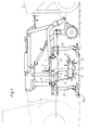
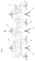
- Figure 1 shows a first embodiment of a tillage machine according to the invention in side view.
- the tillage machine has a short, relatively high frame with two cross bars 1, which are connected at their ends by side plates 2.
- the cross bars 1 are connected approximately in the middle to the longitudinal bars 3 of a frame assembly which has a trestle-like structure 4.
- the frame can be raised and / or connected to a towing vehicle in a generally known manner via upper and lower links of a so-called three-point linkage 5 or the like.
- the frame can be attached to a towing vehicle as shown in Figure 1; However, it is also possible, using the components shown in FIG. 6, to choose a tool arrangement which permits the attachment to the front of a towing vehicle.
- Further tool sequences for secondary soil cultivation for example a leveling rail, can be carried out in a generally known manner via the block-like structure 4 or the frame unit. Drag tines and a harrow to be brought in. It is also possible to use tine rollers which are arranged in a V-shape and follow one another.
- the tine rollers 11, 12 are rotatably mounted on a rocker 10, which is pivotable relative to the frame about an axis Y extending transversely to the direction of travel, so that when the rocker 10 is pivoted one of the tine rollers mounted on it is moved upwards and one tine roller is moved downward.
- the bearings of the tine rollers 11, 12 on the rocker 10 are designed such that wobbling movements of the tine rollers 11, 12 are possible, i.e. there is the possibility that the rocker 10 on one machine side swings in one direction and the rocker 10 on the other machine side in the opposite direction, so that each tine roller 11 or 12 is raised at one side end and lowered at the other side end, wherein the tine rollers 11, 12 are more or less closely intertwined when viewed in the direction of travel.
- the pivotability of the rocker 10 and the tumble-capable mounting of the tine rollers 11, 12 in the rocker ensures that the tine rollers 11, 12 can move freely in relation to the frame during operation, thereby avoiding a too deep immersion of the tines in the earth current can.
- the bearings on the rocker 10 are shielded from dirt by a side cover 15.
- the rocker 10 is height-adjustable on the frame by means of two angle levers 7, which at one end near the front cross member 1 are pivotally arranged in a vertical plane on the side plates 2 and carry at their free end projecting downward from the frame the rocker 10 which is pivotally held about the transverse axis Y on the angle levers 7.
- the substantially horizontally located upper lever part of the angle lever 7 is enclosed near the transition area to the substantially vertical lower lever part by a bracket 8 fastened to the respective side plate 2, which limits the pivoting range of the angle lever 7 relative to the frame towards the bottom.
- a bracket 8 fastened to the respective side plate 2, which limits the pivoting range of the angle lever 7 relative to the frame towards the bottom.
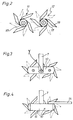
- the tine rollers 11, 12 are largely constructed in the same way. However, the tine rows of the front tine roller 11 are offset relative to the tine rows of the rear tine roller 12 transversely to the direction of travel (see FIG. 2), so that the tines 18 of the two tine rollers 11, 12 mesh like a comb and the tine rollers 11, 12 in the machine longitudinal direction can be arranged at a comparatively short distance.
- the rockers 10 are acted upon by a torque, by means of which the front ends of the rockers 10 or the front tine roller 11 have a lifting tendency and the rear ends of the rocker 10 or the rear tine roller 12 have a lowering tendency.
- a helical tension spring 13 is stretched between the front end of the rocker 10 and a frame-fixed abutment, and in addition a weight 14 is arranged at the rear end of the rocker 10.
- the coil tension spring 13 and the weight 14 can also be used alternatively.
- cultivators 16 are arranged on the two crossbars 1 of the frame, the front cultivators 16 being mounted in front of the front crossbar 1 and the rear cultivators 16 behind the rear crossbar 1, in order to have one despite the short frame length to ensure sufficient longitudinal distance between the cultivators 16 and in particular the necessary distance between the tine rollers 11, 12.
- a heart-shaped design is selected for the share tools 16a, which has a vertical plate designed as stone protection, so that the soil is divided evenly.
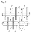
- the tine rollers 11, 12 have a cylindrical axle body 17, on the outer surface of which four teeth 18 are welded, offset by 90 °, which are tangential to the outer surface of the axle body 17 and whose free ends in the direction of travel A of the soil tillage implement predetermined direction of rotation of the tine roller of the respective attachment point on the axle body 17 are trailing.
- the axle body 17 can have a polygonal, in particular a square, cross section, in which case the tine rollers 18 lie flat against the side surfaces of the axle body 17. In this way, a particularly simple and stable attachment of the prongs 18 to the axle body 17 can be achieved.
- the tines 18 consist of square bars with a square or rectangular cross section and are arranged so that a side flank of the square bar rests on the outer surface of the axle body 17.
- the tines 18 are cut obliquely at their free ends so that the resulting tip lies on the outer surface of the tines 18 remote from the axle body 17 and the tip angle is less than or equal to 60 °, in particular approximately 30 °.
- the rear ends of the tines 18 on the axle body side are also cut off at an angle.
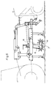
- FIG. 6 shows a second embodiment of a tillage machine according to the invention.
- This embodiment corresponds in its basic structure to the tillage machine shown in FIG. 1 and differs from it essentially in that the rocker 10 is held on the frame so that it can be adjusted in height not by pivoting angle levers 7 but by vertically adjustable supporting parts 20.
- the rear cultivators 16 are followed by guiding tools 21, which are arranged between the cultivators 16 and which are operated by the Close cultivator 16 generated grooves in the ground (see. Fig. 7).
- the tines 18 of a tine roller 11, 12 located in a vertical plane form a closed frame, the end face of the tine 18 formed on the ends of each tine 18 facing away from the free end on the surface facing the axle body 17 of a subsequent tine 18 rests and is welded to this surface of the tine 18 (cf. FIGS. 8 to 10).
- the tine rollers 11, 12 are adjusted in height relative to the frame in order to adjust the machining depth.
- the tine rollers 11, 12 are driven by ground engagement.
- the soil is effectively loosened by pricking the tines 18 before a pivoting movement loosening the ground, the recess being deepened in the course of the pivoting movement.
- peeled earth is thrown from the cultivators 16 in front of and behind the tine rollers 11, 12 from above into the tine rollers 11, 12 and effectively shredded.
- the tines 18 work well and compact the upper soil layer.
Landscapes
- Life Sciences & Earth Sciences (AREA)
- Engineering & Computer Science (AREA)
- Mechanical Engineering (AREA)
- Soil Sciences (AREA)
- Environmental Sciences (AREA)
- Soil Working Implements (AREA)
- Vehicle Body Suspensions (AREA)
Applications Claiming Priority (2)
| Application Number | Priority Date | Filing Date | Title |
|---|---|---|---|
| DE9418722U | 1994-11-25 | ||
| DE9418722U DE9418722U1 (de) | 1994-11-25 | 1994-11-25 | Landwirtschaftliche Bodenbearbeitungsmaschine |
Publications (3)
| Publication Number | Publication Date |
|---|---|
| EP0713636A2 true EP0713636A2 (fr) | 1996-05-29 |
| EP0713636A3 EP0713636A3 (fr) | 1996-06-05 |
| EP0713636B1 EP0713636B1 (fr) | 2002-08-14 |
Family
ID=6916467
Family Applications (1)
| Application Number | Title | Priority Date | Filing Date |
|---|---|---|---|
| EP95118344A Expired - Lifetime EP0713636B1 (fr) | 1994-11-25 | 1995-11-22 | Machine agricole pour le travail du sol |
Country Status (3)
| Country | Link |
|---|---|
| EP (1) | EP0713636B1 (fr) |
| AT (1) | ATE222048T1 (fr) |
| DE (2) | DE9418722U1 (fr) |
Cited By (2)
| Publication number | Priority date | Publication date | Assignee | Title |
|---|---|---|---|---|
| DE29707781U1 (de) * | 1997-04-30 | 1997-09-25 | Rau, Willy, 73230 Kirchheim | Bodenbearbeitungsmaschine für die Landwirtschaft |
| CN120202751A (zh) * | 2025-03-28 | 2025-06-27 | 泰州琴之缘机械加工有限公司 | 一种农业生产用翻土装置及其使用方法 |
Families Citing this family (3)
| Publication number | Priority date | Publication date | Assignee | Title |
|---|---|---|---|---|
| FR2797558B1 (fr) | 1999-08-17 | 2002-01-25 | Const Agricoles Etmetallurgiqu | Machine de travail du sol |
| DE102004023296B4 (de) * | 2004-05-12 | 2006-08-17 | Claus Meyer | Krümelwalze |
| DE102018205887A1 (de) * | 2018-04-18 | 2019-10-24 | Horsch Maschinen Gmbh | Landwirtschaftliche Bodenbearbeitungsmaschine sowie Verfahren zur Bodenbearbeitung |
Family Cites Families (13)
| Publication number | Priority date | Publication date | Assignee | Title |
|---|---|---|---|---|
| DE159487C (fr) * | ||||
| US1911623A (en) * | 1933-05-30 | Assigkob | ||
| US1718510A (en) * | 1928-10-15 | 1929-06-25 | John L Winkler | Rotary hoe attachment for cultivators |
| US1950851A (en) * | 1933-10-03 | 1934-03-13 | Konrad Mathias | Crush pulverizer |
| GB434811A (en) * | 1934-03-03 | 1935-09-03 | Arthur Clive Nicholson | An improved rotary harrow or cultivator |
| US2617343A (en) * | 1946-07-18 | 1952-11-11 | Farm Tools Inc | Reversible rotary implement |
| DE6910520U (de) * | 1969-03-15 | 1969-09-04 | Guenter Steinkampf | Walze zur landwirtschaftlichen bodenbearbeitung |
| DE1960400A1 (de) * | 1969-07-04 | 1971-01-14 | Wissenschaftlich Tech Zentrum | Vorrichtung zur Anpassung von Bodenbearbeitungswerkzeugen |
| US3542139A (en) * | 1969-10-08 | 1970-11-24 | Harry L Mowbray | Rotary harrow wheel |
| IT1041185B (it) * | 1974-08-17 | 1980-01-10 | Rau Ohg Maschf | Rullo stellare per attrezzi agricli |
| US4241793A (en) * | 1979-01-22 | 1980-12-30 | Watkins Murrell G | Rotary hoe scratcher |
| AU583987B2 (en) * | 1986-05-06 | 1989-05-11 | Gregory Ross Kammermann | Improvements in and relating to rotary harrows |
| FR2619667B1 (fr) * | 1987-08-31 | 1991-05-17 | Huard Sa | Perfectionnement aux outils agricoles de reprise de labour |
-
1994
- 1994-11-25 DE DE9418722U patent/DE9418722U1/de not_active Expired - Lifetime
-
1995
- 1995-11-22 AT AT95118344T patent/ATE222048T1/de not_active IP Right Cessation
- 1995-11-22 EP EP95118344A patent/EP0713636B1/fr not_active Expired - Lifetime
- 1995-11-22 DE DE59510321T patent/DE59510321D1/de not_active Expired - Fee Related
Cited By (3)
| Publication number | Priority date | Publication date | Assignee | Title |
|---|---|---|---|---|
| DE29707781U1 (de) * | 1997-04-30 | 1997-09-25 | Rau, Willy, 73230 Kirchheim | Bodenbearbeitungsmaschine für die Landwirtschaft |
| EP0875131A1 (fr) | 1997-04-30 | 1998-11-04 | Willy Rau | Machine agricole de travail du sol |
| CN120202751A (zh) * | 2025-03-28 | 2025-06-27 | 泰州琴之缘机械加工有限公司 | 一种农业生产用翻土装置及其使用方法 |
Also Published As
| Publication number | Publication date |
|---|---|
| ATE222048T1 (de) | 2002-08-15 |
| DE9418722U1 (de) | 1996-04-04 |
| EP0713636A3 (fr) | 1996-06-05 |
| DE59510321D1 (de) | 2002-09-19 |
| EP0713636B1 (fr) | 2002-08-14 |
Similar Documents
| Publication | Publication Date | Title |
|---|---|---|
| DE60037458T3 (de) | Landwirtschaftliches Gerät | |
| CH621233A5 (fr) | ||
| EP0070396A1 (fr) | Cultivateur pour travail profond ayant des rouleaux coopérant avec les outils de travail | |
| DE2617865C2 (fr) | ||
| DE2355802A1 (de) | Verfahren und vorrichtung zur bodenlockerung | |
| DE1557752A1 (de) | Bodenbearbeitungsmaschine | |
| DE3422254A1 (de) | Bodenbearbeitungsmaschine, insbesondere kreiselegge zur saatbettbereitung | |
| DE3541490A1 (de) | Bodenbearbeitungsmaschine | |
| EP0216922A1 (fr) | Machine agricole de labourage du sol. | |
| EP0713636A2 (fr) | Machine agricole pour le travail du sol | |
| DE2849891A1 (de) | Bodenbearbeitungsgeraet | |
| EP0201785B1 (fr) | Machine agricole combinée | |
| DE3343165C2 (fr) | ||
| DE2818274A1 (de) | Verfahren und geraetekombination zur bodenbearbeitung mittels landwirtschaftlicher geraete | |
| DE69432365T2 (de) | Bodenstütze | |
| DE8026930U1 (de) | Vorrichtung zur bodenverarbeitung, insbesondere fuer garten- und parkanlagen | |
| DE3314761A1 (de) | Landwirtschaftliches geraet, insbesondere zur saatbeetbearbeitung | |
| DE69516027T2 (de) | Laudwirtschaftliche Maschine | |
| DE3788224T3 (de) | Gerät zur Bodenbearbeitung. | |
| DE1291158B (de) | Zapfwellenangetriebene Ruettelegge | |
| DE3127263A1 (de) | "geraet zur bodenlockerung" | |
| EP3707978A1 (fr) | Machine de traitement du sol, système de traitement du sol et procédé de traitement du sol | |
| DE69309366T2 (de) | Bodenbearbeitungsmaschine | |
| DE68915056T2 (de) | Bodenbearbeitungsmaschine mit Scharen und einem Rotor. | |
| DE3448328C2 (de) | Bodenbearbeitungsmaschine |
Legal Events
| Date | Code | Title | Description |
|---|---|---|---|
| PUAI | Public reference made under article 153(3) epc to a published international application that has entered the european phase |
Free format text: ORIGINAL CODE: 0009012 |
|
| PUAL | Search report despatched |
Free format text: ORIGINAL CODE: 0009013 |
|
| AK | Designated contracting states |
Kind code of ref document: A2 Designated state(s): AT DE ES FR GB IT |
|
| AK | Designated contracting states |
Kind code of ref document: A3 Designated state(s): AT DE ES FR GB IT |
|
| 17P | Request for examination filed |
Effective date: 19960523 |
|
| 17Q | First examination report despatched |
Effective date: 19980813 |
|
| GRAG | Despatch of communication of intention to grant |
Free format text: ORIGINAL CODE: EPIDOS AGRA |
|
| 19U | Interruption of proceedings before grant |
Effective date: 19990924 |
|
| 19W | Proceedings resumed before grant after interruption of proceedings |
Effective date: 20020201 |
|
| GRAG | Despatch of communication of intention to grant |
Free format text: ORIGINAL CODE: EPIDOS AGRA |
|
| GRAH | Despatch of communication of intention to grant a patent |
Free format text: ORIGINAL CODE: EPIDOS IGRA |
|
| RAP1 | Party data changed (applicant data changed or rights of an application transferred) |
Owner name: MASCHINENFABRIK RAU GMBH |
|
| GRAH | Despatch of communication of intention to grant a patent |
Free format text: ORIGINAL CODE: EPIDOS IGRA |
|
| GRAA | (expected) grant |
Free format text: ORIGINAL CODE: 0009210 |
|
| AK | Designated contracting states |
Kind code of ref document: B1 Designated state(s): AT DE ES FR GB IT |
|
| PG25 | Lapsed in a contracting state [announced via postgrant information from national office to epo] |
Ref country code: IT Free format text: LAPSE BECAUSE OF FAILURE TO SUBMIT A TRANSLATION OF THE DESCRIPTION OR TO PAY THE FEE WITHIN THE PRESCRIBED TIME-LIMIT;WARNING: LAPSES OF ITALIAN PATENTS WITH EFFECTIVE DATE BEFORE 2007 MAY HAVE OCCURRED AT ANY TIME BEFORE 2007. THE CORRECT EFFECTIVE DATE MAY BE DIFFERENT FROM THE ONE RECORDED. Effective date: 20020814 Ref country code: GB Free format text: LAPSE BECAUSE OF FAILURE TO SUBMIT A TRANSLATION OF THE DESCRIPTION OR TO PAY THE FEE WITHIN THE PRESCRIBED TIME-LIMIT Effective date: 20020814 |
|
| REF | Corresponds to: |
Ref document number: 222048 Country of ref document: AT Date of ref document: 20020815 Kind code of ref document: T |
|
| REG | Reference to a national code |
Ref country code: GB Ref legal event code: FG4D Free format text: NOT ENGLISH |
|
| REF | Corresponds to: |
Ref document number: 59510321 Country of ref document: DE Date of ref document: 20020919 |
|
| ET | Fr: translation filed | ||
| PG25 | Lapsed in a contracting state [announced via postgrant information from national office to epo] |
Ref country code: AT Free format text: LAPSE BECAUSE OF NON-PAYMENT OF DUE FEES Effective date: 20021122 |
|
| GBV | Gb: ep patent (uk) treated as always having been void in accordance with gb section 77(7)/1977 [no translation filed] |
Effective date: 20020814 |
|
| PG25 | Lapsed in a contracting state [announced via postgrant information from national office to epo] |
Ref country code: ES Free format text: LAPSE BECAUSE OF FAILURE TO SUBMIT A TRANSLATION OF THE DESCRIPTION OR TO PAY THE FEE WITHIN THE PRESCRIBED TIME-LIMIT Effective date: 20030228 |
|
| PLBI | Opposition filed |
Free format text: ORIGINAL CODE: 0009260 |
|
| PLBF | Reply of patent proprietor to notice(s) of opposition |
Free format text: ORIGINAL CODE: EPIDOS OBSO |
|
| 26 | Opposition filed |
Opponent name: AMAZONEN-WERKEH. DREYER GMBH & CO. KG Effective date: 20030502 |
|
| PLAX | Notice of opposition and request to file observation + time limit sent |
Free format text: ORIGINAL CODE: EPIDOSNOBS2 |
|
| PLAX | Notice of opposition and request to file observation + time limit sent |
Free format text: ORIGINAL CODE: EPIDOSNOBS2 |
|
| PLBP | Opposition withdrawn |
Free format text: ORIGINAL CODE: 0009264 |
|
| PLBB | Reply of patent proprietor to notice(s) of opposition received |
Free format text: ORIGINAL CODE: EPIDOSNOBS3 |
|
| PLBD | Termination of opposition procedure: decision despatched |
Free format text: ORIGINAL CODE: EPIDOSNOPC1 |
|
| PLBM | Termination of opposition procedure: date of legal effect published |
Free format text: ORIGINAL CODE: 0009276 |
|
| STAA | Information on the status of an ep patent application or granted ep patent |
Free format text: STATUS: OPPOSITION PROCEDURE CLOSED |
|
| 27C | Opposition proceedings terminated |
Effective date: 20031030 |
|
| PGFP | Annual fee paid to national office [announced via postgrant information from national office to epo] |
Ref country code: DE Payment date: 20090130 Year of fee payment: 14 |
|
| PG25 | Lapsed in a contracting state [announced via postgrant information from national office to epo] |
Ref country code: DE Free format text: LAPSE BECAUSE OF NON-PAYMENT OF DUE FEES Effective date: 20100601 |
|
| PGFP | Annual fee paid to national office [announced via postgrant information from national office to epo] |
Ref country code: FR Payment date: 20110503 Year of fee payment: 16 |
|
| REG | Reference to a national code |
Ref country code: FR Ref legal event code: ST Effective date: 20120731 |
|
| PG25 | Lapsed in a contracting state [announced via postgrant information from national office to epo] |
Ref country code: FR Free format text: LAPSE BECAUSE OF NON-PAYMENT OF DUE FEES Effective date: 20111130 |