EP0713802A2 - Vorrichtung zum selbsttätigen Einschalten der Beleuchtung eines Kraftfahrzeuges - Google Patents
Vorrichtung zum selbsttätigen Einschalten der Beleuchtung eines Kraftfahrzeuges Download PDFInfo
- Publication number
- EP0713802A2 EP0713802A2 EP95118235A EP95118235A EP0713802A2 EP 0713802 A2 EP0713802 A2 EP 0713802A2 EP 95118235 A EP95118235 A EP 95118235A EP 95118235 A EP95118235 A EP 95118235A EP 0713802 A2 EP0713802 A2 EP 0713802A2
- Authority
- EP
- European Patent Office
- Prior art keywords
- sleeve
- light sensor
- motor vehicle
- mirror
- longitudinal direction
- Prior art date
- Legal status (The legal status is an assumption and is not a legal conclusion. Google has not performed a legal analysis and makes no representation as to the accuracy of the status listed.)
- Granted
Links
- 230000037431 insertion Effects 0.000 claims description 3
- 238000003780 insertion Methods 0.000 claims description 3
Images

Classifications
-
- B—PERFORMING OPERATIONS; TRANSPORTING
- B60—VEHICLES IN GENERAL
- B60Q—ARRANGEMENT OF SIGNALLING OR LIGHTING DEVICES, THE MOUNTING OR SUPPORTING THEREOF OR CIRCUITS THEREFOR, FOR VEHICLES IN GENERAL
- B60Q1/00—Arrangement of optical signalling or lighting devices, the mounting or supporting thereof or circuits therefor
- B60Q1/02—Arrangement of optical signalling or lighting devices, the mounting or supporting thereof or circuits therefor the devices being primarily intended to illuminate the way ahead or to illuminate other areas of way or environments
- B60Q1/04—Arrangement of optical signalling or lighting devices, the mounting or supporting thereof or circuits therefor the devices being primarily intended to illuminate the way ahead or to illuminate other areas of way or environments the devices being headlights
- B60Q1/14—Arrangement of optical signalling or lighting devices, the mounting or supporting thereof or circuits therefor the devices being primarily intended to illuminate the way ahead or to illuminate other areas of way or environments the devices being headlights having dimming means
- B60Q1/1415—Dimming circuits
- B60Q1/1423—Automatic dimming circuits, i.e. switching between high beam and low beam due to change of ambient light or light level in road traffic
-
- B—PERFORMING OPERATIONS; TRANSPORTING
- B60—VEHICLES IN GENERAL
- B60Q—ARRANGEMENT OF SIGNALLING OR LIGHTING DEVICES, THE MOUNTING OR SUPPORTING THEREOF OR CIRCUITS THEREFOR, FOR VEHICLES IN GENERAL
- B60Q2300/00—Indexing codes for automatically adjustable headlamps or automatically dimmable headlamps
- B60Q2300/05—Special features for controlling or switching of the light beam
- B60Q2300/052—Switching delay, i.e. the beam is not switched or changed instantaneously upon occurrence of a condition change
-
- B—PERFORMING OPERATIONS; TRANSPORTING
- B60—VEHICLES IN GENERAL
- B60Q—ARRANGEMENT OF SIGNALLING OR LIGHTING DEVICES, THE MOUNTING OR SUPPORTING THEREOF OR CIRCUITS THEREFOR, FOR VEHICLES IN GENERAL
- B60Q2300/00—Indexing codes for automatically adjustable headlamps or automatically dimmable headlamps
- B60Q2300/30—Indexing codes relating to the vehicle environment
- B60Q2300/31—Atmospheric conditions
- B60Q2300/314—Ambient light
Definitions
- the invention relates to a device for automatically switching on the lighting of a motor vehicle when the value falls below a predefined holiness value.
- a device for automatically switching on the lighting of a motor vehicle when the value falls below a predefined holiness value which has a light sensor which is arranged in a downward-facing and arranged on an outside mirror of the motor vehicle and is effectively connected to the light switch of the motor vehicle.
- the light sensor is advantageously arranged in the underside of the exterior mirror.
- the light sensor is preferably arranged in the interior of a sleeve with its longitudinal direction pointing downward.
- the sleeve is preferably arranged with its longitudinal direction extending perpendicularly in the exterior mirror.
- the sleeve is arranged with its longitudinal direction at an angle of approximately 20 ° to the perpendicular from the motor vehicle in the exterior mirror.
- the light sensor is preferably displaceable and fixable in the sleeve.
- the sleeve preferably has a length of approximately 40 mm.
- the sleeve advantageously has a diameter of approximately 15 mm.
- the lower opening of the sleeve or the light sensor is preferably covered by a polarizing film which is polarized in the longitudinal direction of the sleeve.
- the lower opening of the sleeve or of the light sensor is preferably covered by a viewing window.
- the viewing window is preferably formed in one piece as a clip holder for insertion in the exterior mirror.
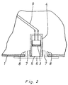
- a downward-directed light sensor 3 is arranged in the underside 1 of an exterior mirror 2 of a motor vehicle, not shown.
- the light sensor sits in a sleeve 4 with a length of approx. 40 mm and a diameter of approx. 15 mm.
- the light sensor 3 is arranged in the sleeve 4 such that it can be moved and fixed.
- the sleeve 4 extends with its longitudinal direction in the vertical direction (FIG. 2) or at an angle W of approximately 20 ° to the vertical, pointing away from the vehicle to the ground (FIG. 1).
- the figures further show that the lower opening of the sleeve 4 is covered by a polarizing film 5 which is polarized in the longitudinal direction of the sleeve. Furthermore, the lower opening of the sleeve 4 is covered by a viewing window 6, which is formed in one piece as a holder 7 for the sleeve 4 and with retaining clips 8 for insertion into the underside 1 of the exterior mirror 2.
- the light sensor 3 is effectively connected to the light switch system of the motor vehicle, not shown, by electrical connecting lines 9.
- the light sensor switches on the lighting of the motor vehicle via the light switch system of the motor vehicle.
- the lighting can be switched off either manually on the light switch system of the motor vehicle or controlled by the light sensor with a suitable delay.
- the arrangement of the light sensor in the underside of the exterior mirror ensures that the light sensor is disturbed as little as possible by extraneous light.
- the polarizing film ensures that only light rays can be incident in the longitudinal direction of the sleeve, since the light rays incident at an angle are deflected.
- the arrangement of the light sensor in the underside of the exterior mirror also ensures that the light sensor is only slightly contaminated, so that the device is reliable for a long time. A height of approx. 80 cm above the ground has given the best results for the mode of operation of the light sensor.
Landscapes
- Engineering & Computer Science (AREA)
- Mechanical Engineering (AREA)
- Lighting Device Outwards From Vehicle And Optical Signal (AREA)
- Rear-View Mirror Devices That Are Mounted On The Exterior Of The Vehicle (AREA)
Abstract
Description
- Die Erfindung betrifft eine Vorrichtung zum selbsttätigen Einschalten der Beleuchtung eines Kraftfahrzeuges bei Unterschreiten eines vorgegebenen Heiligkeitswertes.
- Zahlreiche Unfälle werden darauf zurückgeführt, daß die Fahrzeugführer nicht rechtzeitig bei Dämmerungseinbruch oder schlechten Sichtverhältnissen die Beleuchtung des Kraftfahrzeuges einschalten.
- Es wird daher eine Vorrichtung zum selbsttätigen Einschalten der Beleuchtung eines Kraftfahrzeuges bei Unterschreiten eines vorgegebenen Heiligkeitswertes vorgeschlagen, die einen in einem an einem Außenspiegel des Kraftfahrzeugs angeordneten, nach unten gerichteten Lichtsensors hat, der wirksam mit dem Lichtschalter des Kraftfahrzeuges verbunden ist.
- Vorteilhaft ist der Lichtsensor in der Unterseite des Außenspiegels angeordnet.
- Vorzugsweise ist der Lichtsensor im Innern einer, mit ihrer Längsrichtung nach unten gerichteten Hülse angeordnet. Vorzugsweise ist die Hülse mit ihrer Längsrichtung lotrecht verlaufend im Außenspiegel angeordnet. Bei einer weiteren vorteilhaften Ausführungsform ist die Hülse mit ihrer Längsrichtung in einem Winkel von ca. 20° zur Lotrechten vom Kraftfahrzeug wegweisend im Außenspiegel angeordnet.
- Der Lichtsensor ist vorzugweise in der Hülse verschiebbar und festlegbar angeordnet. Vorzugsweise hat die Hülse eine Länge von ca. 40 mm. Vorteilhaft hat die Hülse einen Durchmesser von ca. 15 mm.
- Die untere Öffnung der Hülse bzw. des Lichtsensors ist vorzugsweise durch eine Polarisationsfolie abgedeckt, die in Hülsenlängsrichtung polarisiert ist.
- Vorzugsweise ist die untere Öffnung der Hülse bzw. des Lichtsensors durch ein Sichtfenster abgedeckt.
- Vorzugsweise ist das Sichtfenster einstückig als Klipphalterung zum Einsetzen in den Außenspiegel ausgebildet.
- Die Erfindung ist in den Zeichnungen beispielhaft dargestellt.
Es zeigen: - Fig. 1
- einen Außenspiegel mit einem eingesetzten Lichtsensor in teilweisem Schnitt und
- Fig. 2
- einen Lichtsensor im Schnitt.
- Nach den Fig. 1 und 2 ist in der Unterseite 1 eines Außenspiegels 2 eines nicht dargestellten Kraftfahrzeuges ein nach unten gerichteter Lichtsensor 3 angeordnet.
- Der Lichtsensor sitzt in einer Hülse 4 mit einer Länge von ca. 40 mm und einem Durchmesser von ca 15 mm. Der Lichtsensor 3 ist in der Hülse 4 verschiebbar und festlegbar angeordnet.
- Wie die Fig. 1 und 2 zeigen, verläuft die Hülse 4 mit ihrer Längsrichtung in lotrechter Richtung (Fig. 2) oder in einem Winkel W von ca. 20° zur Lotrechten, vom Fahrzeug wegweisend zum Boden (Fig. 1).
- Die Figuren zeigen weiter, daß die untere Öffnung der Hülse 4 durch eine Polarisationsfolie 5 abgedeckt, die in Hülsenlängsrichtung polarisiert ist. Weiterhin ist die untere Öffnung der Hülse 4 durch ein Sichtfenster 6 abgedeckt, das einstückig als Halterung 7 für die Hülse 4 und mit Halteklipps 8 zum Einsetzen in die Unterseite 1 des Außenspiegels 2 ausgebildet ist.
- Durch elektrische Verbindungsleitungen 9 ist der Lichtsensor 3 wirksam mit der nicht dargestellten Lichtschaltanlage des Kraftfahrzeuges verbunden.
- Wird eine vorgegebene, einstellbare Helligkeit unterschritten, so schaltet der Lichtsensor über die Lichtschaltanlage des Kraftfahrzeuges die Beleuchtung des Kraftfahrzeuges ein. Das Ausschalten der Beleuchtung kann enweder von Hand an der Lichtschaltanlage des Kraftfahrzeuges oder über den Lichtsensor gesteuert mit einer geeigneten Verzögerung erfolgen.
- Die Anordnung des Lichtsensors in der Unterseite des Außenspiegels gewährleistet eine möglichst geringe Störung des Lichtsensors durch Fremdlicht.
- Durch die Polarisationsfolie wird gewährleitet, daß nur Lichtstrahlen in Längsrichtung der Hülse einfallen können, da die im Winkel auftreffenden Lichtstrahlen abgelenkt werden.
- Die Anordnung des Lichtsensors in der Unterseite des Außenspiegels stellt außerdem sicher, daß der Lichtsensor nur wenig verschmutzt wird, so daß die Vorrichtung lange Zeit betriebssicher ist. Eine Höhe von ca. 80 cm über dem Erdboden hat die besten Ergebnisse für die Wirkungsweise des Lichtsensors ergeben.
Claims (11)
- Vorrichtung zum selbsttätigen Einschalten der Beleuchtung eines Kraftfahrzeuges bei Unterschreiten eines vorgegebenen Helligkeitswertes, gekennzeichnet durch einen in einem Außenspiegel (2) des Kraftfahrzeuges angeordneten, nach unten gerichteten Lichtsensor (3), der wirksam mit dem Lichtschalter des Kraftfahrzeuges verbunden ist.
- Vorrichtung nach Anspruch 1, dadurch gekennzeichnet, daß der Lichtsensor (3) in der Unterseite (1) des Außenspiegels (2) angeordnet ist.
- Vorrichtung nach einem der Ansprüche 1 oder 2, dadurch gekennzeichnet, daß der Lichtsensor (3) im Innern einer, mit ihrer Längsrichtung nach unten gerichteten Hülse (4) angeordnet ist.
- Vorrichtung nach einem der Ansprüche 1 bis 3, dadurch gekennzeichnet, daß die Hülse (4) mit ihrer Längsrichtung lotrecht verlaufend im Außenspiegel (2) angeordnet ist.
- Vorrichtung nach einem der Ansprüche 1 bis 3, dadurch gekennzeichnet, daß die Hülse (4) mit ihrer Längsrichtung in einem Winkel (W) von ca. 20° zur Lotrechten vom Kraftfahrzeug wegweisend im Außenspiegel (2) angeordnet ist.
- Vorrichtung nach einem der Ansprüche 3 bis 5, dadurch gekennzeichnet, daß der Lichtsensor (3) in der Hülse (4) verschiebbar und festlegbar angeordnet ist.
- Vorrichtung nach einem der Ansprüche 3 bis 6, dadurch gekennzeichnet daß die Hülse (4) eine Länge von ca. 40 mm hat.
- Vorrichtung nach einem der Ansprüche 3 bis 7, dadurch gekennzeichnet, daß die Hülse einen Durchmesser von ca. 15 mm hat.
- Vorrichtung nach einem der Ansprüche 1 bis 8, dadurch gekennzeichnet, daß die untere Öffnung der Hülse (4) bzw. des Lichtsensors (3) durch eine Polarisationsfolie (5) abgedeckt ist, die in Hülsenlängsrichtung polarisiert ist.
- Vorrichtung nach einem der Ansprüche 1 bis 9, dadurch gekennzeichnet, daß die untere Öffnung der Hülse (4) bzw. des Lichtsensors (3) durch ein Sichtfenster (6) abgedeckt ist.
- Vorrichtung nach Anspruch 10, dadurch gekennzeichnet, daß das Sichtfenster (6) einstückig als Klipphalterung zum Einsetzen in den Außenspiegel (2) ausgebildet ist.
Applications Claiming Priority (2)
| Application Number | Priority Date | Filing Date | Title |
|---|---|---|---|
| DE9419018U | 1994-11-26 | ||
| DE9419018U DE9419018U1 (de) | 1994-11-26 | 1994-11-26 | Vorrichtung zum selbsttätigen Einschalten der Beleuchtung eines Kraftfahrzeuges |
Publications (3)
| Publication Number | Publication Date |
|---|---|
| EP0713802A2 true EP0713802A2 (de) | 1996-05-29 |
| EP0713802A3 EP0713802A3 (de) | 1997-01-15 |
| EP0713802B1 EP0713802B1 (de) | 1999-05-19 |
Family
ID=6916673
Family Applications (1)
| Application Number | Title | Priority Date | Filing Date |
|---|---|---|---|
| EP95118235A Expired - Lifetime EP0713802B1 (de) | 1994-11-26 | 1995-11-20 | Vorrichtung zum selbsttätigen Einschalten der Beleuchtung eines Kraftfahrzeuges |
Country Status (3)
| Country | Link |
|---|---|
| EP (1) | EP0713802B1 (de) |
| AT (1) | ATE180222T1 (de) |
| DE (2) | DE9419018U1 (de) |
Families Citing this family (1)
| Publication number | Priority date | Publication date | Assignee | Title |
|---|---|---|---|---|
| DE10239840A1 (de) * | 2002-08-29 | 2004-04-01 | Volkswagen Ag | Vorrichtung zum Befestigen einer Sensoreinrichtung in einem Kraftfahrzeug |
Family Cites Families (6)
| Publication number | Priority date | Publication date | Assignee | Title |
|---|---|---|---|---|
| GB1440570A (en) * | 1972-11-28 | 1976-06-23 | Litman M | Rear-view mirror for a motor vehicle |
| JPS60139545A (ja) * | 1983-12-27 | 1985-07-24 | Nippon Denso Co Ltd | 車両用防眩型反射鏡駆動装置 |
| DE3447846A1 (de) * | 1984-12-31 | 1986-07-10 | Heiner 7517 Waldbronn Vogel | Beleuchtungseinrichtung fuer kraftfahrzeuge |
| DE8520564U1 (de) * | 1985-07-17 | 1985-11-07 | Dietsch, Jean G., 6620 Völklingen | Raumform-Innenspiegel für KFZ zur Aufnahme eines Elektronischen Schaltgerätes für die KFZ Beleuchtung |
| US5285060A (en) * | 1992-12-15 | 1994-02-08 | Donnelly Corporation | Display for automatic rearview mirror |
| US5371659A (en) * | 1993-02-01 | 1994-12-06 | Donnelly Corporation | Remote-actuated exterior vehicle security light |
-
1994
- 1994-11-26 DE DE9419018U patent/DE9419018U1/de not_active Expired - Lifetime
-
1995
- 1995-11-20 AT AT95118235T patent/ATE180222T1/de not_active IP Right Cessation
- 1995-11-20 DE DE59505968T patent/DE59505968D1/de not_active Expired - Fee Related
- 1995-11-20 EP EP95118235A patent/EP0713802B1/de not_active Expired - Lifetime
Non-Patent Citations (1)
| Title |
|---|
| None |
Also Published As
| Publication number | Publication date |
|---|---|
| EP0713802A3 (de) | 1997-01-15 |
| EP0713802B1 (de) | 1999-05-19 |
| DE59505968D1 (de) | 1999-06-24 |
| DE9419018U1 (de) | 1995-03-23 |
| ATE180222T1 (de) | 1999-06-15 |
Similar Documents
| Publication | Publication Date | Title |
|---|---|---|
| DE4329983B4 (de) | Dachmodul für ein Kraftfahrzeug | |
| DE19525843C1 (de) | Steckdose mit Beleuchtung | |
| DE3932216C3 (de) | Beleuchtungseinrichtung für Fahrzeuge | |
| DE3737395A1 (de) | Opto-sensorische bedienung der kfz-beleuchtung | |
| DE4232972A1 (de) | Beleuchtungsvorrichtung für eine Gruppe von Bedien- und/oder Anzeigeelementen wenigstens eines Bediengerätes in einem Fahrzeug | |
| EP1200286A1 (de) | Lichtempfindliche sensoreinheit, insbesondere zum automatischen schalten von beleuchtungseinrichtungen | |
| EP0713802A2 (de) | Vorrichtung zum selbsttätigen Einschalten der Beleuchtung eines Kraftfahrzeuges | |
| DE19820348A1 (de) | Vorrichtung zum automatischen Abschalten/Einschalten des Fernlichts bei Kfz, so daß der Gegenverkehr nicht geblendet wird und der Fahrer nicht manuell schalten muß | |
| US4941073A (en) | Wedge shaped flashlight | |
| DE919691C (de) | Beleuchtungseinrichtung fuer Kraftfahrzeuge | |
| DE10249817A1 (de) | Schaltanordnung zur Betätigung von Beleuchtungssystemen an einem Kraftfahrzeug | |
| DE3613556A1 (de) | Rueckblickspiegel fuer kraftfahrzeuge | |
| EP1587117B1 (de) | Einbaugerät | |
| EP4331882A1 (de) | Sonnenblende | |
| DE887748C (de) | Abblendvorrichtung fuer Kraftfahrzeuge | |
| DE919690C (de) | Beleuchtungskoerper fuer Kraftfahrzeuge | |
| DE932831C (de) | Schwenkbarer Zusatzscheinwerfer fuer Fahrzeuge | |
| DE3023477A1 (de) | Vorrichtung zur optischen anzeige des abbremsens eines kraftwagens | |
| DE19922597C2 (de) | Pannenkugel | |
| DE842758C (de) | Mechanisch oder elektrisch betaetigte Blendschutzvorrichtung fuer Kraftfahrzeuge | |
| DE2101541A1 (de) | Umschaltbare Rückleuchteneinheit für Kraftfahrzeuge | |
| DE648779C (de) | Fahrtrichtungsanzeigevorrichtung, insbesondere fuer Fahr- und Motorraeder | |
| DE2508685A1 (de) | Gluehlampenfassung | |
| DE832248C (de) | Abblendvorrichtung fuer Kraftfahrzeuge | |
| DE19637701A1 (de) | Signaleinrichtung und Verfahren zur Signalgebung |
Legal Events
| Date | Code | Title | Description |
|---|---|---|---|
| PUAI | Public reference made under article 153(3) epc to a published international application that has entered the european phase |
Free format text: ORIGINAL CODE: 0009012 |
|
| AK | Designated contracting states |
Kind code of ref document: A2 Designated state(s): AT BE CH DE DK ES FR GB GR IE IT LI LU MC NL PT SE |
|
| AX | Request for extension of the european patent |
Free format text: SI PAYMENT 951207 |
|
| RAX | Requested extension states of the european patent have changed |
Free format text: SI PAYMENT 951207 |
|
| PUAL | Search report despatched |
Free format text: ORIGINAL CODE: 0009013 |
|
| AK | Designated contracting states |
Kind code of ref document: A3 Designated state(s): AT BE CH DE DK ES FR GB GR IE IT LI LU MC NL PT SE |
|
| AX | Request for extension of the european patent |
Free format text: SI PAYMENT 951207 |
|
| 17P | Request for examination filed |
Effective date: 19970304 |
|
| 17Q | First examination report despatched |
Effective date: 19980422 |
|
| GRAG | Despatch of communication of intention to grant |
Free format text: ORIGINAL CODE: EPIDOS AGRA |
|
| GRAG | Despatch of communication of intention to grant |
Free format text: ORIGINAL CODE: EPIDOS AGRA |
|
| GRAH | Despatch of communication of intention to grant a patent |
Free format text: ORIGINAL CODE: EPIDOS IGRA |
|
| GRAH | Despatch of communication of intention to grant a patent |
Free format text: ORIGINAL CODE: EPIDOS IGRA |
|
| GRAA | (expected) grant |
Free format text: ORIGINAL CODE: 0009210 |
|
| AK | Designated contracting states |
Kind code of ref document: B1 Designated state(s): AT BE CH DE DK ES FR GB GR IE IT LI LU MC NL PT SE |
|
| AX | Request for extension of the european patent |
Free format text: SI PAYMENT 19951207 |
|
| PG25 | Lapsed in a contracting state [announced via postgrant information from national office to epo] |
Ref country code: SE Free format text: THE PATENT HAS BEEN ANNULLED BY A DECISION OF A NATIONAL AUTHORITY Effective date: 19990519 Ref country code: NL Free format text: LAPSE BECAUSE OF FAILURE TO SUBMIT A TRANSLATION OF THE DESCRIPTION OR TO PAY THE FEE WITHIN THE PRESCRIBED TIME-LIMIT Effective date: 19990519 Ref country code: IT Free format text: LAPSE BECAUSE OF FAILURE TO SUBMIT A TRANSLATION OF THE DESCRIPTION OR TO PAY THE FEE WITHIN THE PRESCRIBED TIME-LIMIT;WARNING: LAPSES OF ITALIAN PATENTS WITH EFFECTIVE DATE BEFORE 2007 MAY HAVE OCCURRED AT ANY TIME BEFORE 2007. THE CORRECT EFFECTIVE DATE MAY BE DIFFERENT FROM THE ONE RECORDED. Effective date: 19990519 Ref country code: GR Free format text: LAPSE BECAUSE OF NON-PAYMENT OF DUE FEES Effective date: 19990519 Ref country code: GB Free format text: LAPSE BECAUSE OF FAILURE TO SUBMIT A TRANSLATION OF THE DESCRIPTION OR TO PAY THE FEE WITHIN THE PRESCRIBED TIME-LIMIT Effective date: 19990519 Ref country code: FR Free format text: LAPSE BECAUSE OF FAILURE TO SUBMIT A TRANSLATION OF THE DESCRIPTION OR TO PAY THE FEE WITHIN THE PRESCRIBED TIME-LIMIT Effective date: 19990519 Ref country code: ES Free format text: THE PATENT HAS BEEN ANNULLED BY A DECISION OF A NATIONAL AUTHORITY Effective date: 19990519 |
|
| REF | Corresponds to: |
Ref document number: 180222 Country of ref document: AT Date of ref document: 19990615 Kind code of ref document: T |
|
| REG | Reference to a national code |
Ref country code: CH Ref legal event code: EP |
|
| REG | Reference to a national code |
Ref country code: IE Ref legal event code: FG4D Free format text: GERMAN |
|
| REF | Corresponds to: |
Ref document number: 59505968 Country of ref document: DE Date of ref document: 19990624 |
|
| PG25 | Lapsed in a contracting state [announced via postgrant information from national office to epo] |
Ref country code: PT Free format text: LAPSE BECAUSE OF FAILURE TO SUBMIT A TRANSLATION OF THE DESCRIPTION OR TO PAY THE FEE WITHIN THE PRESCRIBED TIME-LIMIT Effective date: 19990819 Ref country code: DK Free format text: LAPSE BECAUSE OF FAILURE TO SUBMIT A TRANSLATION OF THE DESCRIPTION OR TO PAY THE FEE WITHIN THE PRESCRIBED TIME-LIMIT Effective date: 19990819 |
|
| EN | Fr: translation not filed | ||
| GBV | Gb: ep patent (uk) treated as always having been void in accordance with gb section 77(7)/1977 [no translation filed] |
Effective date: 19990519 |
|
| PG25 | Lapsed in a contracting state [announced via postgrant information from national office to epo] |
Ref country code: LU Free format text: LAPSE BECAUSE OF NON-PAYMENT OF DUE FEES Effective date: 19991120 Ref country code: IE Free format text: LAPSE BECAUSE OF NON-PAYMENT OF DUE FEES Effective date: 19991120 Ref country code: AT Free format text: LAPSE BECAUSE OF NON-PAYMENT OF DUE FEES Effective date: 19991120 |
|
| PG25 | Lapsed in a contracting state [announced via postgrant information from national office to epo] |
Ref country code: LI Free format text: LAPSE BECAUSE OF NON-PAYMENT OF DUE FEES Effective date: 19991130 Ref country code: DE Free format text: LAPSE BECAUSE OF NON-PAYMENT OF DUE FEES Effective date: 19991130 Ref country code: CH Free format text: LAPSE BECAUSE OF NON-PAYMENT OF DUE FEES Effective date: 19991130 Ref country code: BE Free format text: LAPSE BECAUSE OF NON-PAYMENT OF DUE FEES Effective date: 19991130 |
|
| PLBE | No opposition filed within time limit |
Free format text: ORIGINAL CODE: 0009261 |
|
| STAA | Information on the status of an ep patent application or granted ep patent |
Free format text: STATUS: NO OPPOSITION FILED WITHIN TIME LIMIT |
|
| 26N | No opposition filed | ||
| BERE | Be: lapsed |
Owner name: HOFFMANN EWALD Effective date: 19991130 |
|
| PG25 | Lapsed in a contracting state [announced via postgrant information from national office to epo] |
Ref country code: MC Free format text: LAPSE BECAUSE OF NON-PAYMENT OF DUE FEES Effective date: 20000531 |
|
| REG | Reference to a national code |
Ref country code: CH Ref legal event code: PL |
|
| REG | Reference to a national code |
Ref country code: IE Ref legal event code: MM4A |