EP0714031B1 - Verfahren zur Kontaktdiagnose an Elektroanlagen - Google Patents
Verfahren zur Kontaktdiagnose an Elektroanlagen Download PDFInfo
- Publication number
- EP0714031B1 EP0714031B1 EP95117985A EP95117985A EP0714031B1 EP 0714031 B1 EP0714031 B1 EP 0714031B1 EP 95117985 A EP95117985 A EP 95117985A EP 95117985 A EP95117985 A EP 95117985A EP 0714031 B1 EP0714031 B1 EP 0714031B1
- Authority
- EP
- European Patent Office
- Prior art keywords
- temperature
- contact
- connection
- time
- resistance
- Prior art date
- Legal status (The legal status is an assumption and is not a legal conclusion. Google has not performed a legal analysis and makes no representation as to the accuracy of the status listed.)
- Expired - Lifetime
Links
- 238000003745 diagnosis Methods 0.000 title claims abstract description 11
- 238000000034 method Methods 0.000 title claims description 10
- 238000010616 electrical installation Methods 0.000 title claims 2
- 230000005855 radiation Effects 0.000 claims description 6
- 230000008569 process Effects 0.000 claims description 4
- 230000007613 environmental effect Effects 0.000 abstract description 3
- 238000011835 investigation Methods 0.000 abstract 1
- 238000010438 heat treatment Methods 0.000 description 10
- 239000004020 conductor Substances 0.000 description 9
- 230000032683 aging Effects 0.000 description 8
- 238000005259 measurement Methods 0.000 description 8
- 230000000694 effects Effects 0.000 description 4
- 238000011156 evaluation Methods 0.000 description 4
- 230000007774 longterm Effects 0.000 description 4
- 238000002405 diagnostic procedure Methods 0.000 description 3
- 238000005516 engineering process Methods 0.000 description 3
- XAGFODPZIPBFFR-UHFFFAOYSA-N aluminium Chemical compound [Al] XAGFODPZIPBFFR-UHFFFAOYSA-N 0.000 description 2
- 229910052782 aluminium Inorganic materials 0.000 description 2
- 230000005540 biological transmission Effects 0.000 description 2
- 230000001419 dependent effect Effects 0.000 description 2
- 238000004870 electrical engineering Methods 0.000 description 2
- 239000000463 material Substances 0.000 description 2
- 241001136792 Alle Species 0.000 description 1
- 238000002835 absorbance Methods 0.000 description 1
- 238000004364 calculation method Methods 0.000 description 1
- 230000008859 change Effects 0.000 description 1
- 230000000052 comparative effect Effects 0.000 description 1
- 150000001875 compounds Chemical class 0.000 description 1
- 230000005611 electricity Effects 0.000 description 1
- 238000002474 experimental method Methods 0.000 description 1
- 238000005338 heat storage Methods 0.000 description 1
- 238000009413 insulation Methods 0.000 description 1
- 238000012423 maintenance Methods 0.000 description 1
- 238000000691 measurement method Methods 0.000 description 1
- 238000012821 model calculation Methods 0.000 description 1
- 238000012545 processing Methods 0.000 description 1
- 230000008439 repair process Effects 0.000 description 1
- 238000012360 testing method Methods 0.000 description 1
- 238000001931 thermography Methods 0.000 description 1
- 230000036962 time dependent Effects 0.000 description 1
- 238000012546 transfer Methods 0.000 description 1
Images


Classifications
-
- G—PHYSICS
- G01—MEASURING; TESTING
- G01R—MEASURING ELECTRIC VARIABLES; MEASURING MAGNETIC VARIABLES
- G01R27/00—Arrangements for measuring resistance, reactance, impedance, or electric characteristics derived therefrom
- G01R27/02—Measuring real or complex resistance, reactance, impedance, or other two-pole characteristics derived therefrom, e.g. time constant
- G01R27/20—Measuring earth resistance; Measuring contact resistance, e.g. of earth connections, e.g. plates
- G01R27/205—Measuring contact resistance of connections, e.g. of earth connections
-
- G—PHYSICS
- G01—MEASURING; TESTING
- G01J—MEASUREMENT OF INTENSITY, VELOCITY, SPECTRAL CONTENT, POLARISATION, PHASE OR PULSE CHARACTERISTICS OF INFRARED, VISIBLE OR ULTRAVIOLET LIGHT; COLORIMETRY; RADIATION PYROMETRY
- G01J5/00—Radiation pyrometry, e.g. infrared or optical thermometry
- G01J5/48—Thermography; Techniques using wholly visual means
-
- G—PHYSICS
- G01—MEASURING; TESTING
- G01R—MEASURING ELECTRIC VARIABLES; MEASURING MAGNETIC VARIABLES
- G01R31/00—Arrangements for testing electric properties; Arrangements for locating electric faults; Arrangements for electrical testing characterised by what is being tested not provided for elsewhere
- G01R31/50—Testing of electric apparatus, lines, cables or components for short-circuits, continuity, leakage current or incorrect line connections
- G01R31/66—Testing of connections, e.g. of plugs or non-disconnectable joints
Definitions
- the invention relates to the diagnosis of connections electrical engineering according to the generic term of Claim 1.
- connection diagnosis or contact diagnosis must be carried out.
- the electrical energy transport to the consumer can often not be interrupted during diagnosis.
- the decisive physical variable for determining an upper limit value for assessing a connection is a maximum permissible connection resistance, which results from a permissible limit temperature.
- connection resistance In activated electrical systems, the resistance of the connection is measured directly by a current-voltage measurement. On the other hand, it is not possible to measure the connection resistance directly on the live and inaccessible connections and connections of electrical equipment. In these cases, the connection resistance can be determined indirectly via its effect, ie via the temperature of the connection. Since the state of the connection, expressed by the size of the connection resistance, is reflected by the temperature, infrared measurement technology (infrared camera) is used for diagnosis.
- infrared measurement technology infrared camera
- connection resistance is known, a mathematical aging model according to Böhme, H .; Löbl, H .: “On the theory of the long-term behavior of aluminum screw connections", Elektrie 41 (87) 5, pp. 179/83 and Bergmann, R .: “On the long-term behavior of the resistance of electrical busbar connections", thesis 1995 TU Dresden The course of the increase in resistance can be calculated. The time ⁇ t R remaining until the limit value is reached is called the remaining service life.
- the object of the invention is therefore, in the context of contactless diagnosis of connections in electrical engineering systems, the instantaneous connection resistance R V , taking into account all significant, time-varying parameters influencing the temperature of the contact connection, such as load current, wind speed and wind direction, ambient temperature, sun and Capture and evaluate sky radiation.
- the contact resistance should be non-contact be determined under a high electrical voltage stands and is transmitted via the electrical energy.
- the dynamic heating network is taken from the heating network library or, if necessary, newly developed. Over a sufficient period of time, the temperature distribution and the temperature profile at the connection are measured and recorded with an infrared camera, for example. At the same time, all essential dynamic influencing variables are recorded and also recorded. These sizes are usually: load current, wind speed and direction, power of solar and sky radiation and ambient temperature. They are entered as time-dependent data for calculating the temperature in the heating network which represents the respective connection to be examined. From this, both the temperature profile and the temperature distribution for the connection to be diagnosed with the connected conductor are calculated. By comparing the measured and calculated temperatures, these temperatures can be adapted to one another while changing the connection resistance to be diagnosed. If the course and distribution match, the desired resistance Ru is determined.
- connection resistance must be calculated from the measured temperature and the parameters influencing it. If the resistance is known, depending on the current load to be expected, the remaining service life ⁇ t R is determined using the service life model for electrical connections.
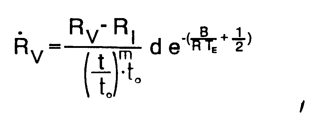
- This model records the aging rate R ⁇ V depending on the connection resistance R V and the resistance of the connection with ideal contact R I , the temperature at the narrow point T E and the foreign layer growth occurring there ( ⁇ t -m ).
- connection resistance can by comparison with predetermined limit values. Depending on the difference between the measured connection resistance and a limit must be decided whether the connection continues until the next check may be operated or whether an immediate renewal necessary is.
- the resistance of a connection can be done with this method contactless without interrupting the energy transport be determined, and a trend statement is made with the measurement on the further operability of the examined Connection.
- connection resistance R V determined via the dynamic heating network, much more precise statements about the remaining service life ⁇ t R are possible. Connections can be diagnosed so reliably with the new diagnostic procedure that the point in time of a necessary energy interruption (shutdown) can be derived as a result of a maintenance-related exchange of outdated electrical equipment.
- the resistance of a T branch terminal 1 must be determined under operating conditions. Based on the connection resistance R V 9, the remaining service life ⁇ t R 11 of the connection must be determined depending on the future current load. From the remaining service life 11, it can be derived when the connection has to be renewed or upgraded. For this purpose, an infrared camera 2 is used over a period of time which is approximately 10 minutes. is, the temperature curve and the temperature distribution of the connection and the connected three conductors 1 recorded up to a distance of three times the local constant from the connection 1.
- the temperature distribution and the temperature profile 6 for the arrangement 1 are calculated depending on the data recorded by 3.1 to 3.4. Parallel to the calculation, there is also a comparison of the temperature 7 measured with the infrared camera 2 and calculated by the heating network model 8. If the two temperature profiles 7 and 8 for connection 1 do not match, the connection resistance R V in the heating network program 5 is changed until both The courses are congruent. The resistance that led to this match is the connection resistance R V 9 that is being sought.
- the service life model 10 can be used to calculate the service life t L and the remaining service life ⁇ t R 11, depending on the expected current load, and to determine the time of a repair (renewal).
- the temperature profiles shown in FIG. 2 relate on a T-branch clamp (aluminum) with rope Al / St 240/40; the one with the infrared camera 2 and a thermometer 3.4 measured temperature profiles of the T-branch terminal 7 and the surrounding area 12 over a period of 50 minutes compared with calculated temperature profiles 8, 13 and 14.
- connection resistance R V in the heating network program 5 By changing the connection resistance R V in the heating network program 5, the calculated temperature profile 8 is adjusted to the measured temperature profile 7.
- the area integral below the curves was used as a criterion for the adjustment of both profiles.
- the connection resistance is considered to be determined if these integrals are of equal size.
- the aging model according to FIG. 3 can be used to calculate the time after which a limit resistance R VG for the connection has been reached.
- the time that lies between the time of the measurement t M and the reaching of the limit resistance R VG is referred to as the remaining service life ⁇ t R.
- How quickly the limit resistance R VG is reached depends largely on the current load to be expected during the time ⁇ t R.
- the effect of the load current is taken into account in the equation, which describes aging, via the temperature T E at the bottlenecks of the contact.
- the limit resistance R VG depends on the electrical properties of adjacent insulation and conductor materials. It is determined based on experience or calculated using limit temperatures.
Landscapes
- Physics & Mathematics (AREA)
- General Physics & Mathematics (AREA)
- Spectroscopy & Molecular Physics (AREA)
- Testing Of Devices, Machine Parts, Or Other Structures Thereof (AREA)
- Radiation Pyrometers (AREA)
- Coupling Device And Connection With Printed Circuit (AREA)
- Testing Or Measuring Of Semiconductors Or The Like (AREA)
- Testing Of Short-Circuits, Discontinuities, Leakage, Or Incorrect Line Connections (AREA)
- Investigating Or Analyzing Materials Using Thermal Means (AREA)
Description
Um den Zustand der Verbindungen einschätzen zu können bzw. um Ausfälle von Anlagen der Elektroenergieübertragung zu vermeiden, muß eine Verbindungsdiagnose bzw. Kontaktdiagnose durchgeführt werden. Der Elektroenergietransport zum Verbraucher kann bei der Diagnose oft nicht unterbrochen werden.
Da sich der Zustand der Verbindung, ausgedrückt durch die Größe des Verbindungswiderstandes, über die Temperatur abbildet, wird zur Diagnose die Infrarotmeßtechnik (Infrarotkamera) eingesetzt.
- Windgeschwindigkeit und Windrichtung (in Freiluftanlagen),
- Sonnen- und Himmelsstrahlung (in Freiluftanlagen),
- Umgebungstemperatur,
- Geometrie der Verbindung und der angeschlossenen Leiter sowie deren Wärmespeicher- und Wärmeleitvermögen
- elektrisches Leitvermögen der angeschlossenen Leiter
- Absorptions- und Emissionsvermögen der Verbindung und der Leiter
- Ähnlichkeitsfunktionen des konvektiven Wärmeübergangs für Verbindung und Leiter
- temperaturabhängige Stoffwerte der Luft.
Über eine ausreichende Zeitspanne wird an der Verbindung die Temperaturverteilung und der Temperaturverlauf mit z.B. einer Infrarotkamera gemessen und aufgezeichnet. Zeitgleich werden alle wesentlichen dynamischen Einflußgrößen erfaßt und ebenfalls aufgezeichnet. Diese Größen sind in der Regel: Belastungsstrom, Windgeschwindigkeit und -richtung, Leistung der Sonnen-und Himmelsstrahlung und Umgebungstemperatur. Sie werden als zeitabhängige Daten zur Berechnung der Temperatur in das die jeweilig zu untersuchende Verbindung abbildende Wärmenetz eingegeben. Daraus werden sowohl Temperaturverlauf als auch Temperaturverteilung für die zu diagnostizierende Verbindung mit dem angeschlossenen Leiter berechnet. Durch Vergleich der gemessenen und berechneten Temperaturen können unter Veränderung des zu diagnostizierenden Verbindungswiderstandes diese Temperaturen einander angepaßt werden. Stimmen Verlauf und Verteilung überein, ist der gesuchte Widerstand Ru ermittelt.
Es kann bei beliebigen Ausgangsbedingungen, wie Umgebungstemperatur, Windgeschwindigkeit u.a.m. gearbeitet werden.
- Fig. 1
- die schematische Darstellung des Meßverfahrens zur Bestimmung der Restnutzungsdauer einer elektrischen Verbindung,
- Fig. 2
- die Darstellung der Bestimmung des Verbindungswiderstandes RV aus gemessenem und berechnetem Temperaturverlauf,
- Fig. 3
- die Bestimmung der Restnutzungsdauer aus dem über das Alterungsmodell berechneten Lebensdauerverlauf.
Der Widerstand einer T-Abzweigklemme 1 ist unter Betriebsbedingungen zu ermitteln. Ausgehend vom Verbindungswiderstand RV 9 ist abhängig von der zukünftigen Strombelastung die Restnutzungsdauer ΔtR 11 der Verbindung zu ermitteln. Aus der Restnutzungsdauer 11 ist abzuleiten, wann die Erneuerung oder Ertüchtigung der Verbindung zu erfolgen hat. Dazu werden mit einer Infrarotkamera 2 über einen Zeitraum, der etwa 10 min. beträgt, der Temperaturverlauf und die Temperaturverteilung der Verbindung und der angeschlossenen drei Leiter 1 bis zu einem Abstand von jeweils der dreifachen Ortskonstante von der Verbindung 1 aufgezeichnet.
- Belastungsstrom 3.1
- Windgeschwindigkeit und -richtung 3.2
- Leistung durch Sonnen- und Himmelsstrahlung 3.3
- Umgebungstemperatur 3.4
Alle Daten, die durch die Infrarotkamera 2 und die Umgebungsparameter 3 aufzunehmen und zu speichern sind, werden zur weiteren Verarbeitung im Wärmenetzmodell dem dynamischen Wärmenetz 5 übergeben.
Parallel zur Berechnung erfolgt auch ein Vergleich der mit der Infrarotkamera 2 gemessenen 7 und durch das Wärmenetzmodell berechneten Temperatur 8. Stimmen die beiden Temperaturverläufe 7 und 8 für die Verbindung 1 nicht überein, so wird der Verbindungswiderstand RV im Wärmenetzprogramm 5 solange verändert, bis beide Verläufe deckungsgleich sind. Der Widerstand, der zu dieser Übereinstimmung geführt hat, ist der gesuchte Verbindungswiderstand RV 9.
Claims (3)
- Verfahren zur Kontaktdiagnose an Elektroanlagen mit Hilfe der Infrarotmeßtechnik,
dadurch gekennzeichnet, daß über eine bestimmte Zeit an der zu untersuchenden Kontaktverbindung (1) die Temperaturverteilung berührungslos (2) gemessen und aufgezeichnet wird undzeitgleich alle für die Temperaturverteilung wesentlichen dynamischen Einflußgrößen (3), wie Belastungsstrom (3.1), Windgeschwindigkeit und -richtung (3.2), Leistung der Sonnen- und Himmelsstrahlung (3.3) sowie Umgebungstemperatur (3.4) gemessen und ebenfalls aufgezeichnet (4) werden unddie Werte der erfaßten Einflußgrößen als zeitabhängige Daten in ein die jeweilige untersuchte Kontaktverbindung adäquat beschreibendes Wärmenetz (5) eingegeben wird, woraus sowohl der Temperaturverlauf (6) als auch die Temperaturverteilung für die zu diagnostizierende Verbindung berechnet werden und durch Vergleich der gemessenen (7) und berechneten Temperaturen (8) unter Veränderung des zu diagnostizierenden Verbindungswiderstandes RV (9) die Temperaturverläufe angepaßt werden, wobei für den Fall, daß Verlauf und Verteilung übereinstimmen der gesuchte Widerstand RV (9) vorliegt. - Verfahren nach Anspruch 1,
dadurch gekennzeichnet, daß das die zu diagnostizierende Verbindung am besten beschreibende Wärmenetz einer Wärmenetzbibliothek entnommen wird. - Verfahren nach einem der Ansprüche 1 oder 2,
dadurch gekennzeichnet, daß die Dauer des Meßverfahrens pro zu untersuchender Kontaktverbindung (1) etwa 10 min beträgt.
Applications Claiming Priority (2)
| Application Number | Priority Date | Filing Date | Title |
|---|---|---|---|
| DE4442070A DE4442070A1 (de) | 1994-11-25 | 1994-11-25 | Verfahren zur Kontaktdiagnose an Elektroanlagen |
| DE4442070 | 1994-11-25 |
Publications (2)
| Publication Number | Publication Date |
|---|---|
| EP0714031A1 EP0714031A1 (de) | 1996-05-29 |
| EP0714031B1 true EP0714031B1 (de) | 2000-05-17 |
Family
ID=6534191
Family Applications (1)
| Application Number | Title | Priority Date | Filing Date |
|---|---|---|---|
| EP95117985A Expired - Lifetime EP0714031B1 (de) | 1994-11-25 | 1995-11-15 | Verfahren zur Kontaktdiagnose an Elektroanlagen |
Country Status (3)
| Country | Link |
|---|---|
| EP (1) | EP0714031B1 (de) |
| AT (1) | ATE193124T1 (de) |
| DE (2) | DE4442070A1 (de) |
Cited By (1)
| Publication number | Priority date | Publication date | Assignee | Title |
|---|---|---|---|---|
| CN102788645A (zh) * | 2012-07-18 | 2012-11-21 | 西安交通大学 | 电力设备电连接点温升红外监测系统及监测方法 |
Families Citing this family (9)
| Publication number | Priority date | Publication date | Assignee | Title |
|---|---|---|---|---|
| DE10139837A1 (de) * | 2001-08-14 | 2003-02-27 | Bsh Bosch Siemens Hausgeraete | Anordnung und Verfahren zur automatischen Überprüfung wenigstens einer zur elektrischen Kontaktierung dienenden Steckverbindung |
| DE102005007227A1 (de) | 2005-02-15 | 2006-08-17 | Siemens Ag | Anordnung mit einem elektrischen Leiter zur Übertragung elektrischer Energie sowie Verfahren zur Ermittlung der Belastung eines elektrischen Leiters |
| DE102008054511A1 (de) * | 2008-12-11 | 2010-06-17 | Robert Bosch Gmbh | Verfahren zum Bestimmen eines Zustands mindestens einer Komponente eines Steuergeräts |
| CN103344839B (zh) * | 2013-07-01 | 2015-08-05 | 江苏大学 | 一种母线接头接触电阻无线检测方法及装置 |
| FR3039335B1 (fr) * | 2015-07-22 | 2017-08-11 | Peugeot Citroen Automobiles Sa | Procede de protection contre les sur-echauffements et/ou les surintensites d’un connecteur electrique |
| CN108344921A (zh) * | 2017-01-25 | 2018-07-31 | 珠海格力电器股份有限公司 | 空调电连接状态的检测方法、系统及空调器 |
| CN111722029B (zh) * | 2019-03-21 | 2023-03-07 | 杭州海康威视数字技术股份有限公司 | 一种网络摄像机供电方式的侦测装置、方法及网络摄像机 |
| CN110907150B (zh) * | 2019-10-15 | 2020-11-24 | 杭州电子科技大学 | 一种机器人接插件可靠性加速测试方法 |
| CN112254817B (zh) * | 2020-09-16 | 2023-08-01 | 广西大学 | 带电设备红外检测的精确故障诊断方法 |
Family Cites Families (6)
| Publication number | Priority date | Publication date | Assignee | Title |
|---|---|---|---|---|
| DE2336389C2 (de) * | 1973-07-17 | 1975-05-28 | Siemens Ag, 1000 Berlin U. 8000 Muenchen | Vorrichtung zur Prüfung des Ubergangswiderstandes einer Steckverbindung |
| US3991302A (en) * | 1974-11-22 | 1976-11-09 | Grumman Aerospace Corporation | Method for detecting and isolating faults in digital and analog circuits with multiple infrared scanning under conditions of different stimuli |
| US4584523A (en) * | 1983-10-03 | 1986-04-22 | Rca Corporation | Measurement of the current flow in an electric power transmission line by detection of infrared radiation therefrom |
| DE3711421A1 (de) * | 1987-04-04 | 1988-10-20 | Messerschmitt Boelkow Blohm | Pruefeinrichtung |
| DE4123116C1 (de) * | 1991-07-12 | 1992-06-17 | Leopold Kostal Gmbh & Co Kg, 5880 Luedenscheid, De | |
| DE4123870A1 (de) * | 1991-07-18 | 1993-01-21 | Elli Tutsch | Verfahren zur ueberwachung elektronischer baugruppen und vorrichtung zu seiner durchfuehrung |
-
1994
- 1994-11-25 DE DE4442070A patent/DE4442070A1/de not_active Withdrawn
-
1995
- 1995-11-15 AT AT95117985T patent/ATE193124T1/de active
- 1995-11-15 EP EP95117985A patent/EP0714031B1/de not_active Expired - Lifetime
- 1995-11-15 DE DE59508347T patent/DE59508347D1/de not_active Expired - Lifetime
Cited By (2)
| Publication number | Priority date | Publication date | Assignee | Title |
|---|---|---|---|---|
| CN102788645A (zh) * | 2012-07-18 | 2012-11-21 | 西安交通大学 | 电力设备电连接点温升红外监测系统及监测方法 |
| CN102788645B (zh) * | 2012-07-18 | 2014-08-20 | 西安交通大学 | 电力设备电连接点温升红外监测系统及监测方法 |
Also Published As
| Publication number | Publication date |
|---|---|
| DE59508347D1 (de) | 2000-06-21 |
| DE4442070A1 (de) | 1996-05-30 |
| ATE193124T1 (de) | 2000-06-15 |
| EP0714031A1 (de) | 1996-05-29 |
Similar Documents
| Publication | Publication Date | Title |
|---|---|---|
| EP0714031B1 (de) | Verfahren zur Kontaktdiagnose an Elektroanlagen | |
| DE102016225089A1 (de) | Diagnosesystem und Diagnoseverfahren für Photovoltaik-Leistungserzeugungssystem | |
| DE102007003754A1 (de) | Temperiervorrichtung mit Kalibrierungseinrichtung | |
| DE112018005230T5 (de) | Trendfunktionen zum vorhersagen der intaktheit von elektrischen energieanlagen | |
| CN111121971A (zh) | 一种通过高压开关柜表面温度变化判断故障类型的方法 | |
| DE112017007532B4 (de) | Alterungsdegradationsdiagnosevorrichtung und alterungsdegradationsdiagnoseverfahren | |
| WO2017089185A1 (de) | Verfahren zum bestimmen von schwellenwerten einer zustandsueberwachungseinheit für eine brandmelder- und/oder loeschsteuerzentrale sowie zustandsueberwachungseinheit und system damit | |
| EP3289657A1 (de) | Verfahren zum prüfen der stränge an solarmodulen einer photovoltaikanlage und photovoltaik-wechselrichter zur durchführung des verfahrens | |
| DE202004021438U1 (de) | Anordnung von Sensorelementen zum zuverlässigen Messen einer Temperatur | |
| EP3390997B1 (de) | Vorrichtung und verfahren zur sicheren und genauen bestimmung der temperatur eines mediums | |
| EP3284149B1 (de) | Verfahren und anordnung für einen betrieb einer elektrischen anlage unter benützung eines thermischen modells dessen | |
| DE102016207527B4 (de) | Verfahren zum Erfassen des Zustandes einer Verbindung von Bauteilen | |
| DE102014101156B4 (de) | Vorrichtung zum Bestimmen eines Messwerts in einer elektrischen Anlage und Verfahren | |
| DE102019214472B3 (de) | Verfahren zur Bestimmung der ortsaufgelösten thermischen Strukturfunktion und/oder Zeitkonstantenspektren eines Objekts | |
| DE102012206512A1 (de) | Beheizbares Gasanalysengerät | |
| WO2023117251A1 (de) | Zustandsanalyse eines elektrischen betriebsmittels | |
| DE102015222357A1 (de) | Verfahren und Vorrichtung zum Messen und Charakterisieren eines thermoelektrischen Moduls | |
| WO2016071032A1 (de) | Messanordnung umfassend ein erstes und ein zweites paar von thermodrähten | |
| Jamshidi Eini et al. | Defect detection and preventive maintenance prioritization of distribution cubicles by infrared statistical image processing | |
| DE102023208338B4 (de) | Erkennen einer thermischen Überlastung von Komponenten einer Schaltanlage | |
| EP2839303B1 (de) | Verfahren zum bestimmen der leistungsfähigkeit von photovoltaikanlagen | |
| EP1837646B1 (de) | Verfahren und Vorrichtung zur Ermittlung der Feuchte eines Gases | |
| DE20220276U1 (de) | Vorrichtung zur Überwachung eines elektrischen Stromnetzes | |
| CN119575248A (zh) | 一种管型母线运行智能监测系统及方法 | |
| DE4011485A1 (de) | Verfahren zum messen der temperatur beim anschweissen eines verbinders an eine solarzelle |
Legal Events
| Date | Code | Title | Description |
|---|---|---|---|
| PUAI | Public reference made under article 153(3) epc to a published international application that has entered the european phase |
Free format text: ORIGINAL CODE: 0009012 |
|
| AK | Designated contracting states |
Kind code of ref document: A1 Designated state(s): AT CH DE LI NL SE |
|
| 17P | Request for examination filed |
Effective date: 19960823 |
|
| RAP1 | Party data changed (applicant data changed or rights of an application transferred) |
Owner name: RIBE-HAW ELEKTROTECHNIK GMBH & CO. KG |
|
| GRAG | Despatch of communication of intention to grant |
Free format text: ORIGINAL CODE: EPIDOS AGRA |
|
| GRAG | Despatch of communication of intention to grant |
Free format text: ORIGINAL CODE: EPIDOS AGRA |
|
| GRAG | Despatch of communication of intention to grant |
Free format text: ORIGINAL CODE: EPIDOS AGRA |
|
| GRAH | Despatch of communication of intention to grant a patent |
Free format text: ORIGINAL CODE: EPIDOS IGRA |
|
| 17Q | First examination report despatched |
Effective date: 19991005 |
|
| GRAH | Despatch of communication of intention to grant a patent |
Free format text: ORIGINAL CODE: EPIDOS IGRA |
|
| GRAA | (expected) grant |
Free format text: ORIGINAL CODE: 0009210 |
|
| AK | Designated contracting states |
Kind code of ref document: B1 Designated state(s): AT CH DE LI NL SE |
|
| REF | Corresponds to: |
Ref document number: 193124 Country of ref document: AT Date of ref document: 20000615 Kind code of ref document: T |
|
| REG | Reference to a national code |
Ref country code: CH Ref legal event code: EP |
|
| REF | Corresponds to: |
Ref document number: 59508347 Country of ref document: DE Date of ref document: 20000621 |
|
| REG | Reference to a national code |
Ref country code: CH Ref legal event code: NV Representative=s name: OK PAT AG |
|
| EN | Fr: translation not filed | ||
| PLBE | No opposition filed within time limit |
Free format text: ORIGINAL CODE: 0009261 |
|
| STAA | Information on the status of an ep patent application or granted ep patent |
Free format text: STATUS: NO OPPOSITION FILED WITHIN TIME LIMIT |
|
| REG | Reference to a national code |
Ref country code: CH Ref legal event code: PUE Owner name: RIBE-HAW ELEKTROTECHNIK GMBH & CO. KG TRANSFER- SI Ref country code: CH Ref legal event code: NV Representative=s name: SIEMENS SCHWEIZ AG |
|
| 26N | No opposition filed | ||
| NLS | Nl: assignments of ep-patents |
Owner name: SIEMENS AKTIENGESELLSCHAFT |
|
| REG | Reference to a national code |
Ref country code: CH Ref legal event code: PCAR Free format text: SIEMENS SCHWEIZ AG;INTELLECTUAL PROPERTY FREILAGERSTRASSE 40;8047 ZUERICH (CH) |
|
| PGFP | Annual fee paid to national office [announced via postgrant information from national office to epo] |
Ref country code: CH Payment date: 20140206 Year of fee payment: 19 Ref country code: DE Payment date: 20140120 Year of fee payment: 19 |
|
| PGFP | Annual fee paid to national office [announced via postgrant information from national office to epo] |
Ref country code: SE Payment date: 20141106 Year of fee payment: 20 |
|
| PGFP | Annual fee paid to national office [announced via postgrant information from national office to epo] |
Ref country code: NL Payment date: 20141103 Year of fee payment: 20 Ref country code: AT Payment date: 20141009 Year of fee payment: 20 |
|
| REG | Reference to a national code |
Ref country code: DE Ref legal event code: R119 Ref document number: 59508347 Country of ref document: DE |
|
| REG | Reference to a national code |
Ref country code: CH Ref legal event code: PL |
|
| PG25 | Lapsed in a contracting state [announced via postgrant information from national office to epo] |
Ref country code: LI Free format text: LAPSE BECAUSE OF NON-PAYMENT OF DUE FEES Effective date: 20141130 Ref country code: CH Free format text: LAPSE BECAUSE OF NON-PAYMENT OF DUE FEES Effective date: 20141130 |
|
| PG25 | Lapsed in a contracting state [announced via postgrant information from national office to epo] |
Ref country code: DE Free format text: LAPSE BECAUSE OF NON-PAYMENT OF DUE FEES Effective date: 20150602 |
|
| REG | Reference to a national code |
Ref country code: NL Ref legal event code: MK Effective date: 20151114 |
|
| REG | Reference to a national code |
Ref country code: AT Ref legal event code: MK07 Ref document number: 193124 Country of ref document: AT Kind code of ref document: T Effective date: 20151115 |