EP0714054A2 - Installation de dosage et de répartition pour une émulsion de découpage - Google Patents
Installation de dosage et de répartition pour une émulsion de découpage Download PDFInfo
- Publication number
- EP0714054A2 EP0714054A2 EP95117783A EP95117783A EP0714054A2 EP 0714054 A2 EP0714054 A2 EP 0714054A2 EP 95117783 A EP95117783 A EP 95117783A EP 95117783 A EP95117783 A EP 95117783A EP 0714054 A2 EP0714054 A2 EP 0714054A2
- Authority
- EP
- European Patent Office
- Prior art keywords
- emulsion
- mixing container
- line
- supply unit
- bypass line
- Prior art date
- Legal status (The legal status is an assumption and is not a legal conclusion. Google has not performed a legal analysis and makes no representation as to the accuracy of the status listed.)
- Withdrawn
Links
- 239000000839 emulsion Substances 0.000 title claims abstract description 53
- 238000002156 mixing Methods 0.000 claims abstract description 33
- 239000007921 spray Substances 0.000 claims abstract description 32
- 238000000265 homogenisation Methods 0.000 claims description 5
- 230000001050 lubricating effect Effects 0.000 claims description 4
- 239000012141 concentrate Substances 0.000 abstract description 11
- XLYOFNOQVPJJNP-UHFFFAOYSA-N water Substances O XLYOFNOQVPJJNP-UHFFFAOYSA-N 0.000 abstract description 9
- 235000014113 dietary fatty acids Nutrition 0.000 abstract description 3
- 229930195729 fatty acid Natural products 0.000 abstract description 3
- 239000000194 fatty acid Substances 0.000 abstract description 3
- 150000004665 fatty acids Chemical class 0.000 abstract description 3
- 125000003118 aryl group Chemical group 0.000 abstract 1
- 238000005086 pumping Methods 0.000 abstract 1
- 235000008429 bread Nutrition 0.000 description 7
- 239000000203 mixture Substances 0.000 description 5
- 238000004806 packaging method and process Methods 0.000 description 5
- 238000005507 spraying Methods 0.000 description 5
- 230000000694 effects Effects 0.000 description 4
- 238000000034 method Methods 0.000 description 4
- 230000008569 process Effects 0.000 description 4
- 230000001105 regulatory effect Effects 0.000 description 4
- 235000012424 soybean oil Nutrition 0.000 description 3
- 239000003549 soybean oil Substances 0.000 description 3
- 230000001960 triggered effect Effects 0.000 description 3
- 241000196324 Embryophyta Species 0.000 description 2
- 239000003795 chemical substances by application Substances 0.000 description 2
- 238000005259 measurement Methods 0.000 description 2
- 238000003756 stirring Methods 0.000 description 2
- 238000011144 upstream manufacturing Methods 0.000 description 2
- 230000009471 action Effects 0.000 description 1
- 230000002411 adverse Effects 0.000 description 1
- 230000008901 benefit Effects 0.000 description 1
- 230000003115 biocidal effect Effects 0.000 description 1
- 230000033228 biological regulation Effects 0.000 description 1
- 230000006735 deficit Effects 0.000 description 1
- 238000013461 design Methods 0.000 description 1
- 238000011161 development Methods 0.000 description 1
- 238000010586 diagram Methods 0.000 description 1
- 230000007613 environmental effect Effects 0.000 description 1
- 230000002349 favourable effect Effects 0.000 description 1
- 235000013305 food Nutrition 0.000 description 1
- 230000006872 improvement Effects 0.000 description 1
- 239000007788 liquid Substances 0.000 description 1
- 244000005700 microbiome Species 0.000 description 1
- 238000012544 monitoring process Methods 0.000 description 1
- 239000002244 precipitate Substances 0.000 description 1
- 239000000047 product Substances 0.000 description 1
- 230000011664 signaling Effects 0.000 description 1
- 230000000087 stabilizing effect Effects 0.000 description 1
- 239000008399 tap water Substances 0.000 description 1
- 235000020679 tap water Nutrition 0.000 description 1
Images
Classifications
-
- G—PHYSICS
- G05—CONTROLLING; REGULATING
- G05D—SYSTEMS FOR CONTROLLING OR REGULATING NON-ELECTRIC VARIABLES
- G05D11/00—Control of flow ratio
- G05D11/02—Controlling ratio of two or more flows of fluid or fluent material
- G05D11/13—Controlling ratio of two or more flows of fluid or fluent material characterised by the use of electric means
- G05D11/131—Controlling ratio of two or more flows of fluid or fluent material characterised by the use of electric means by measuring the values related to the quantity of the individual components
- G05D11/132—Controlling ratio of two or more flows of fluid or fluent material characterised by the use of electric means by measuring the values related to the quantity of the individual components by controlling the flow of the individual components
Definitions
- the invention relates to a metering and distribution system according to the preamble of claim 1.
- soybean oil as a cutting aid is common in the bread industry, by means of which, for example, knives are sprayed, which occurs in different amounts depending on the type of bread to be treated in each case.
- this cutting aid leads to a significant environmental impairment, since this agent spreads in the form of the finest droplets in an uncontrolled manner in the environment, precipitates it, brings odor nuisance to the staff working here, and likewise spreads microorganisms of the most varied types kind of favors.
- the use of this cutting aid is burdened by hygienic problems, the mastery of which involves a great deal of effort.
- an aqueous emulsion which can contain natural fatty acids, natural flavorings and other components which, for example, develop a biocidal action, but whose use is harmless from the point of view of food hygiene.
- An advantage of this cutting aid is that the fat atmosphere that occurs during a soybean oil spray is avoided.
- This object is achieved in such a system by the features of the characterizing part of claim 1.
- the starting point is an aqueous emulsion to which at least one further component is added, a sprayable emulsion being formed from these two components in a mixing container and being kept ready.
- This sprayable emulsion is placed in a supply unit, which is arranged downstream of the mixing container - as seen in the direction of flow of the emulsion - under a pressure which is suitable and sufficient for supplying the spray nozzles mentioned.
- the spray nozzles are designed to be controllable, in particular with regard to quantitative metering of the emulsion delivered.
- the individual components of this emulsion are only emulsified within the plant according to the invention, care having to be taken by suitable measures that an uncontrolled escape of both the sprayable emulsion and individual components thereof from the plant is prevented.
- the operation of said device, the mixing container and the supply unit is regulated by means of a higher-level control in accordance with the amount of emulsion required in each case.
- a dosing and distribution system for a cutting or lubricating emulsion is available, which is suitable for a precisely dosed and customized application of the emulsion at the respective points of action.
- the latter are, for example, knives, but also transport chains and parts connected to them.
- said device is designed as a proportional metering pump, the mixing tank being provided with a level control in connection with the higher-level control device and a level monitor, so that the level of the mixing tank is either kept constant or within predeterminable, in each case a lower and an upper level of descriptive levels is maintained.
- the proportional metering pump is therefore only activated when emulsion is removed from the mixing container and its fill level drops accordingly.
- the proportional metering pump is expediently equipped with separate lines for the components of the emulsion which lead to the mixing container, the proportions of the individual components being adjustable.
- this is equipped with a homogenizing unit which is arranged in a bypass line which, according to the features of claim 3, has, inter alia, a high-performance mixer.
- a homogenizing unit which is arranged in a bypass line which, according to the features of claim 3, has, inter alia, a high-performance mixer.
- This can be configured, for example, as an ultraturax, with a flow chamber being arranged below the lower fill level of the mixing container.
- the high-performance mixer is expediently actuated at intervals, for example when the mixing container is refilled or otherwise in accordance with predeterminable time intervals. It is essential in this respect that the distribution state of the emulsion is stabilized in this way within the mixing container.
- the upper connection of the bypass line - seen in a cross-sectional plane of the mixing container - extends at an angle to a radius line, there is a hydraulic stirring effect which also contributes to the homogenization of the emulsion.
- a stirrer can naturally also be used for this measure.
- the hydraulic stirring effect is supported by the high-performance mixer, which generates an overpressure above the flow chamber, so that there is a sufficient flow rate.
- the bypass line is further equipped with a sensor for detecting the proportions of the components of the emulsion in accordance with the features of claim 5.
- a sensor for detecting the proportions of the components of the emulsion in accordance with the features of claim 5.
- the sensor can be a measuring electrode that detects electrical conductivity.
- the purpose of the supply unit is, according to the features of claim 6, to put the emulsion under as constant a pressure as possible, by means of which a distributor block is applied on the inlet side, which is connected on the outlet side via intermediate pressure regulating units and subsequent emulsion lines to the spray nozzles mentioned.
- claims 7 to 9 are directed to a further embodiment of the supply unit.
- a pneumatically drivable pump is preferably used in its frame, since it can be regulated in the simplest way.
- the distributor block is inserted into a bypass line, from which a line leads back to the supply unit.
- a contribution to stabilizing the emulsion is also made in this way.
- the pressure control units arranged downstream of the supply unit, in particular the distributor block preferably enable individual pressure control of each emulsion line. In this way, there are optimal possibilities to adapt the spray pressure at each spray nozzle to the technical requirements there.
- claims 10 to 12 are directed to the further development of the spray nozzles. These are designed to be pneumatically controllable and stand in operative connection with the control device. In order to ensure that the emulsion is used as economically as possible, the spray nozzles are only operated in cycles, the triggering control signal for these spray nozzles being derived directly from the movement of a knife, a transport chain or another machine part.
- the emulsion is metered according to requirements and in particular also to the product.
- the homogenizing unit in particular the high-performance mixer there, is also designed in accordance with the features of claims 13 to 14 for a cyclical operation oriented to actual needs. It is essential here that the emulsion is kept in a stable state.
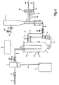
- Fig. 1 is a proportional metering pump, the input side with a water pipe 2 and one, a concentrate of natural fatty acids and Aroma leading line 3 is connected.
- the water line 2 leads to a main connection, not shown, while the line 3 is connected to a storage container 4 containing the concentrate mentioned.
- the proportional metering pump 1 enables the delivery of water and concentrate, in accordance with a preferably predeterminable quantitative ratio.
- the proportional metering pump 1 is designed such that the water is conveyed separately from the concentrate, so that separate outlet lines are also provided.
- only one outlet line 5 for the water is shown, in the course of which a valve 6, which can preferably be operated electromagnetically, is arranged.
- An output line carrying the concentrate is not shown in the drawing.
- the maximum flow of the valve 6 is expediently limited. This is achieved by installing a flow regulator 51 upstream of the valve 6.
- the mixing container 7 is connected on the input side to the output line 5 and a further line carrying the concentrate, these two lines being connected to the mixing container below the uppermost liquid level within the mixing container.
- the mixing container 7 is with a level monitor 8 equipped, which preferably works according to electrical functional principles and generates corresponding measurement signals when an upper fill level 9 and a lower fill level 10 are reached.
- a fill level is designated by 11, which triggers an alarm message via the fill level monitor 8 or in some other way.
- This fill level 11 is still below the lower fill level 10 and defines an extreme limit value which must not be undercut.
- a homogenizing unit which includes a high-performance mixer 13, here an Ultraturax, which is arranged in a bypass line 14 of the mixing container 7.
- This bypass line 14 leads from the lowermost end of the mixing container via the high-performance mixer 13 back to an area adjacent to the upper end of the mixing container 7.
- the high-performance mixer 13, which is operated at very high speeds, generates a negative pressure with respect to its flow chamber on the inlet side and an excess pressure on the outlet side and effects sufficient mixing of the two components, namely the concentrate and the water, in such a way that an emulsion characterized by the finest distribution of the concentrate is formed. At the same time, this state of the emulsion is maintained by this homogenizing unit 12.
- a measuring electrode can be arranged at a suitable point on the bypass line 14, which, for example, enables the respective dosing or the composition of the cutting emulsion provided to be determined by measuring the electrical conductivity. On a graphical representation of this measuring electrode has been omitted.
- the bypass line 14 is connected to a supply unit 17 via a branch line 16 secured by a valve 15.
- the supply unit 17 serves to provide the cutting emulsion under a constant pressure and leads on the output side via a line 18 and a filter 19 to a distributor block 20, from which a bypass line (not shown in the drawing) leads back to the supply unit 17.
- the generally minor return flowing through this bypass line further contributes to keeping the supply pressure constant.
- the supply unit also consists of a pneumatically driven booster pump, which brings the cutting emulsion to a constant pressure.
- the compressed air supply line 21 of the supply unit 17, which leads via a pressure control unit 22 and a filter 23, is designated by 21, the latter line being connected to a compressed air source, not shown in the drawing.
- control device 28 denotes a control device which serves for the energy supply, but in particular for measurement, control or regulation purposes. An illustration of associated electrical connecting lines has, however, been dispensed with.
- This control device (28) is designed as a programmable logic controller (PLC control). It serves, among other things, to control the valve 6 in accordance with the level of the mixing container 7 signaled by the level monitor 8, the control of the homogenization unit 12, for example the setting of an operation with a defined run-on time, for example six minutes when a new mixture is added or when the system is idle according to a timed operation, after which the homogenization unit is switched on for a time interval of, for example, six minutes after every two hours.
- PLC control programmable logic controller
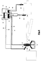
- the drawing shows, by way of example, spray nozzles 39, 40 which are assigned to a knife 41, spray nozzles 42, 43 which are assigned to a transport chain 44 or a gear wheel 45 thereof, and a spray nozzle 46 which can be activated during the inflation of bags used for packaging bread is.
- the two spray nozzles 39, 40 cooperating with the knife 41 are connected to the pressure control unit 29 via a line 47, while the remaining spray nozzles 42, 43 and 46 are each connected to the pressure control units 30 and 31 via lines 48, 49 and 50 stand.
- the emulsion fed to the spray nozzles 39, 40 is under a lower pressure than the emulsions which are fed to the respective spray nozzles 42, 43 and 46 via the lines 48, 49 and 50.
- the pressure control units 29, 30, 31 enable the individual pressure setting, which is in each case related to the individual spray nozzle or to groups of spray nozzles.
- the actuation namely opening of the spray nozzles 39, 40 takes place as a function of the actuation of the knife 41.
- Spraying via the spray nozzles 42, 43 takes place in cycles during the advance of the transport chain 44, wherein different time cycles can be specified for the spraying of the transport chain on the one hand and the gearwheel on the other hand.
- the spraying process via the nozzle 46 is linked to the process of inflating the bags which serve to package the sliced bread.
- the packaging bag is sprayed during inflation, which takes about two seconds to pack 500 g of bread, for example.
- the arrangement of the spray nozzles shown along a cutting line up to the packaging of the sliced bread is only to be understood as an example and, in particular, further spray nozzles can also be provided at a suitable point. It is essential that the control of the individual spray nozzles takes place pneumatically and is triggered in an adjustable manner by the movement of the knife, the transport chain or other processes during packaging according to predeterminable time cycles. For the sake of clarity, corresponding electrical control lines have again not been shown in the drawing.
- a constant pressure in the lines 47 to 50 is maintained in each case via the pressure control units 29 to 31, and further emulsion from the bypass line 14 of the mixing container 7 via the distributor block 20 (FIG. 1) or the supply line 17 is tracked and, with a corresponding decrease in the level of emulsion within the mixing container 7 via the control 28, further emulsion 6 is provided by corresponding actuation of the valve.
- Emulsion quantities are kept as small as possible, so that there are hardly any adverse effects on the surroundings of the spray nozzles and there is a substantial improvement in the hygienic conditions compared to the prior art set out at the beginning.
- the water content of the cutting or lubricating emulsion has a favorable effect.
Landscapes
- Physics & Mathematics (AREA)
- General Physics & Mathematics (AREA)
- Engineering & Computer Science (AREA)
- Automation & Control Theory (AREA)
Applications Claiming Priority (2)
| Application Number | Priority Date | Filing Date | Title |
|---|---|---|---|
| DE4442094 | 1994-11-25 | ||
| DE4442094 | 1994-11-25 |
Publications (2)
| Publication Number | Publication Date |
|---|---|
| EP0714054A2 true EP0714054A2 (fr) | 1996-05-29 |
| EP0714054A3 EP0714054A3 (fr) | 1996-11-27 |
Family
ID=6534208
Family Applications (1)
| Application Number | Title | Priority Date | Filing Date |
|---|---|---|---|
| EP95117783A Withdrawn EP0714054A3 (fr) | 1994-11-25 | 1995-11-11 | Installation de dosage et de répartition pour une émulsion de découpage |
Country Status (1)
| Country | Link |
|---|---|
| EP (1) | EP0714054A3 (fr) |
Cited By (2)
| Publication number | Priority date | Publication date | Assignee | Title |
|---|---|---|---|---|
| WO1999056189A1 (fr) * | 1998-04-30 | 1999-11-04 | The Boc Group, Inc. | Systeme de regulation asservi par conductivite pour operation de melange visant a elaborer une suspension epaisse |
| DE102014224736A1 (de) * | 2014-12-03 | 2016-06-09 | Sandvik Materials Technology Deutschland Gmbh | Vorrichtung und Verfahren zum Pastillieren eines fließfähigen Produkts |
Family Cites Families (7)
| Publication number | Priority date | Publication date | Assignee | Title |
|---|---|---|---|---|
| DE1161140B (de) * | 1956-12-04 | 1964-01-09 | Daimler Benz Ag | Vorrichtung zum Mischen von zaehen Fluessigkeiten in einem einstellbaren Verhaeltnismit in gegenseitiger Drehzahlabhaengigkeit antreibbaren Foerderpumpen |
| DE2862294D1 (en) * | 1978-08-09 | 1983-08-25 | R E Folland Consultants Inc | Emulsifying system and method for mixing accurate quantities of two or more liquids |
| US4823987A (en) * | 1986-04-28 | 1989-04-25 | Ryco Graphic Manufacturing, Inc. | Liquid mixing system and method |
| GB2205386B (en) * | 1987-06-02 | 1990-03-07 | Aeci Ltd | Cartridging of explosives |
| US5074671A (en) * | 1990-11-13 | 1991-12-24 | Dew Engineering And Development Limited | Mixing apparatus |
| BR9201543A (pt) * | 1992-04-16 | 1993-10-19 | Lopes Homero & Ass Ltda | Processo de queima de emulsao hidro-oleosa |
| JPH05304994A (ja) * | 1992-04-30 | 1993-11-19 | Reika Kogyo Kk | ペニシリンの連続式抽出装置及び抽出方法 |
-
1995
- 1995-11-11 EP EP95117783A patent/EP0714054A3/fr not_active Withdrawn
Non-Patent Citations (1)
| Title |
|---|
| None |
Cited By (8)
| Publication number | Priority date | Publication date | Assignee | Title |
|---|---|---|---|---|
| WO1999056189A1 (fr) * | 1998-04-30 | 1999-11-04 | The Boc Group, Inc. | Systeme de regulation asservi par conductivite pour operation de melange visant a elaborer une suspension epaisse |
| US6796703B2 (en) | 1998-04-30 | 2004-09-28 | The Boc Group, Inc. | Conductivity feedback control system for slurry bending |
| DE102014224736A1 (de) * | 2014-12-03 | 2016-06-09 | Sandvik Materials Technology Deutschland Gmbh | Vorrichtung und Verfahren zum Pastillieren eines fließfähigen Produkts |
| CN107107390A (zh) * | 2014-12-03 | 2017-08-29 | 山特维克材料技术德国有限公司 | 用于使能流动的产品成锭的装置和方法 |
| KR20170100542A (ko) * | 2014-12-03 | 2017-09-04 | 산드빅 마테리알스 테크놀로지 도이칠란트 게엠베하 | 유동성 제품의 정제화 장치 및 방법 |
| DE102014224736B4 (de) * | 2014-12-03 | 2017-10-19 | Sandvik Materials Technology Deutschland Gmbh | Vorrichtung und Verfahren zum Pastillieren eines fließfähigen Produkts |
| US20170326760A1 (en) * | 2014-12-03 | 2017-11-16 | Sandvik Materials Technology Deutschland Gmbh | Device and method for pastillating a flowable product |
| US10675603B2 (en) | 2014-12-03 | 2020-06-09 | Ipco Germany Gmbh | Device and method for pastillating a flowable product |
Also Published As
| Publication number | Publication date |
|---|---|
| EP0714054A3 (fr) | 1996-11-27 |
Similar Documents
| Publication | Publication Date | Title |
|---|---|---|
| EP0463007B1 (fr) | Dispositif pour appliquer des agents traitant les vegetaux | |
| DE69826804T2 (de) | Flüssigkeitsverteilvorrichtung und Verfahren | |
| CH674319A5 (fr) | ||
| EP1932423B1 (fr) | Dispositif de pulvérisation | |
| DE3602024A1 (de) | Verfahren und vorrichtung zum herstellen eines fliessfaehigen, zu schaumstoff ausreagierenden gemisches aus fliessfaehigen komponenten | |
| DE1782349A1 (de) | Pumpvorrichtung zum Bemessen und Zumessen von Fluessigkeiten | |
| DE102014224736B4 (de) | Vorrichtung und Verfahren zum Pastillieren eines fließfähigen Produkts | |
| DE3639245C2 (fr) | ||
| EP1932424B2 (fr) | Dispositif de pulvérisation | |
| DE2540146A1 (de) | Mit oelzerstaeubung arbeitende schmiervorrichtung an einer schleifmaschine | |
| WO2018228713A1 (fr) | Procédé et dispositif de mélange pour la régulation de l'introduction d'une substance sous forme de poudre dans un liquide pour un procédé de mélange par lots | |
| DE69823430T2 (de) | Automatisches Fahrzeugwaschsystem mit Benutzung von Waschmittelkonzentraten | |
| DE20114393U1 (de) | Vorrichtung zur Aufbringung von versprühbaren Flüssigkeiten | |
| DE69114163T2 (de) | Handhabung eines Mehrkomponentenklebers. | |
| EP1320415B1 (fr) | Dispositif pour l'application de liquides a pulveriser | |
| EP0478944B1 (fr) | Dispositif pour doser et mélanger deux composants fluides | |
| EP2698445B1 (fr) | Dispositif et procédé destinés au revêtement de pièces métalliques | |
| EP0714596A1 (fr) | Installation d'alimentation pour la distribution de mélanges d'affouragement | |
| DE2029138C3 (de) | Verfahren und Vorrichtung zum synchronen Dosieren von zwei oder mehr fließfähigen, miteinander zu mischenden Komponenten | |
| EP3711864B1 (fr) | Procédé de régulation de la pression d'alimentation dans un système de recirculation pour un dispositif de revêtement et système de recirculation | |
| DE69113142T2 (de) | Dosiervorrichtung von flüssigen Stoffen für landwirtschaftliche Maschinen. | |
| EP0137450B1 (fr) | Procédé et dispositif pour mouiller des matières solides versables | |
| EP0932502A1 (fr) | Procede et installation de preparation de pate d'impression ou similaire, notamment d'impression de bandes de textiles ou de tapis | |
| AT404466B (de) | Kraftstoffgemisch-ausgabevorrichtung | |
| DE3434443C2 (fr) |
Legal Events
| Date | Code | Title | Description |
|---|---|---|---|
| PUAI | Public reference made under article 153(3) epc to a published international application that has entered the european phase |
Free format text: ORIGINAL CODE: 0009012 |
|
| 17P | Request for examination filed |
Effective date: 19951117 |
|
| AK | Designated contracting states |
Kind code of ref document: A2 Designated state(s): BE DE FR GB IT NL |
|
| PUAL | Search report despatched |
Free format text: ORIGINAL CODE: 0009013 |
|
| AK | Designated contracting states |
Kind code of ref document: A3 Designated state(s): BE DE FR GB IT NL |
|
| STAA | Information on the status of an ep patent application or granted ep patent |
Free format text: STATUS: THE APPLICATION HAS BEEN WITHDRAWN |
|
| 18W | Application withdrawn |
Withdrawal date: 19961206 |