EP0714112B1 - Lampe à décharge à culot unique - Google Patents
Lampe à décharge à culot unique Download PDFInfo
- Publication number
- EP0714112B1 EP0714112B1 EP19950308008 EP95308008A EP0714112B1 EP 0714112 B1 EP0714112 B1 EP 0714112B1 EP 19950308008 EP19950308008 EP 19950308008 EP 95308008 A EP95308008 A EP 95308008A EP 0714112 B1 EP0714112 B1 EP 0714112B1
- Authority
- EP
- European Patent Office
- Prior art keywords
- tube
- legs
- bonding material
- lamp according
- support member
- Prior art date
- Legal status (The legal status is an assumption and is not a legal conclusion. Google has not performed a legal analysis and makes no representation as to the accuracy of the status listed.)
- Expired - Lifetime
Links
- 239000000463 material Substances 0.000 claims description 26
- 239000011521 glass Substances 0.000 claims description 10
- 239000004568 cement Substances 0.000 claims description 8
- 229920001187 thermosetting polymer Polymers 0.000 claims description 4
- 230000001419 dependent effect Effects 0.000 claims 1
- 238000004519 manufacturing process Methods 0.000 description 2
- 239000000853 adhesive Substances 0.000 description 1
- 230000001070 adhesive effect Effects 0.000 description 1
- 230000000694 effects Effects 0.000 description 1
- 238000010438 heat treatment Methods 0.000 description 1
- 239000002184 metal Substances 0.000 description 1
- -1 polybutylene terephthalate Polymers 0.000 description 1
- 229920001707 polybutylene terephthalate Polymers 0.000 description 1
- 229920005989 resin Polymers 0.000 description 1
- 239000011347 resin Substances 0.000 description 1
- 239000002904 solvent Substances 0.000 description 1
Images
Classifications
-
- H—ELECTRICITY
- H01—ELECTRIC ELEMENTS
- H01J—ELECTRIC DISCHARGE TUBES OR DISCHARGE LAMPS
- H01J61/00—Gas-discharge or vapour-discharge lamps
- H01J61/02—Details
- H01J61/30—Vessels; Containers
- H01J61/32—Special longitudinal shape, e.g. for advertising purposes
- H01J61/327—"Compact"-lamps, i.e. lamps having a folded discharge path
-
- H—ELECTRICITY
- H01—ELECTRIC ELEMENTS
- H01J—ELECTRIC DISCHARGE TUBES OR DISCHARGE LAMPS
- H01J5/00—Details relating to vessels or to leading-in conductors common to two or more basic types of discharge tubes or lamps
- H01J5/50—Means forming part of the tube or lamps for the purpose of providing electrical connection to it
- H01J5/54—Means forming part of the tube or lamps for the purpose of providing electrical connection to it supported by a separate part, e.g. base
- H01J5/58—Means for fastening the separate part to the vessel, e.g. by cement
Definitions
- the present invention relates to a discharge lamp.
- Single-ended discharge lamps primarily compact fluorescent lamps, are commercially available which have a discharge tube comprising four or six glass legs.
- the ends of the legs of the discharge tube are fixed inside a tube support part of a housing with a thermosetting cement.
- the cement is placed between the legs of the tube and the outer rim of the tube supporting part.
- the cement is set by heating it and keeping it at a given temperature for a certain time. During this time the cement swells and sets and bonds to the glass tube legs and to the outer rim of the tube supporting part.
- the tube legs are fixed in the tube supporting part.
- a single ended discharge lamp comprising a discharge tube having a plurality of glass legs, the ends of which are held in a tube support member by bonding material which bonds the said ends to the support member, characterised in that the bonding material is arranged substantially symmetrically with respect to each of the said ends.
- the invention is based on the recognition that mechanical forces are exerted to the glass by the bonding material which further increases the stresses generated in the glass in earlier stages of manufacturing.
- the stresses produced in this way are reduced, in accordance with the invention, by fixing the ends of tube glass legs of the discharge tube inside the tube support member with bonding material applied not only to the outer portion of the support member surrounding the tube ends but also to the inner portion of the discharge tube bordered by the tube legs.
- a single-ended discharge lamp having a discharge tube comprising at least two tube glass legs, and a housing for mechanical and electrical connection to a lampholder, which housing comprises a tube supporting part, a connection part and a lamp cap, holes in the tube supporting part through which the legs of the discharge tube extend with the ends of the legs of the discharge tube inside the housing fixed with a bonding material applied to the outside portion of the tube supporting part which portion surrounds the discharge tube and, furthermore, the ends of the legs of the discharge tube are fixed to the tube supporting part with bonding material also applied to the inside portion of the discharge tube bordered by the tube legs.
- a rib on the tube supporting part, the ends of the legs being between the rib and the rim.
- the rib extends towards the inside of the housing and supports the bonding material. Thereby, both the rib and the outer rim of the tube supporting part support the bonding material and ensure that the force generated by the bonding material is taken up.
- the bonding material may be a thermosetting cement which swells when setting.
- the glass tube legs are not exposed to asymmetrical load, so that they are more evenly mechanically stressed.
- the solution according to the invention provides a bond between the tube legs and the housing which withstands higher mechanical loads.
- the invention is particularly advantageous when the discharge tube has six, eight or more tube legs.
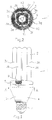
- the discharge lamp according to Figures 1 and 2 is an OCT type compact fluorescent lamp having a discharge tube 2 having eight glass legs 3a to 3h and a ballast housing 4.
- Discharge tube 2 contains electrodes (not shown) and a gas and metal vapor fill as known in the art.
- the eight tube legs 3a, 3b, 3c, 3d, 3e, 3f, 3g, 3h have an outside diameter of about 12mm.
- the legs are joined one to another to form a continuous discharge space.
- Housing 4 comprises a tube supporting portion 5, a housing portion 6 and a lamp cap 7, e.g. an Edison screw cap.
- the supporting part 5 has circular openings, the centres of which are on a circle of 37 mm diameter.
- the openings accept the tube legs 3a, 3b, 3c, 3d, 3e, 3f, 3g, 3h of the discharge tube 2.
- tube supporting part 5 there is an integral, radially inner rib 10 which projects towards the inside of housing 4.
- the rib 10 is cylindrical and has a thickness of 1 mm, a height of 6.5 mm, and an inside diameter of 20 mm.
- the rib 10 is concentric with the outer circular rim 8 of the supporting part 5.
- the rim 8 has a wall thickness of 2 mm and an outside diameter of 53.5 mm.
- Tube supporting part 5 and housing portion 6 are of plastic material, e.g. polybutylene terephthalate, and are fixed to each other by snapping then together, or by adhesive.
- Lamp cap 7 is fixed to housing portion 6.
- An electronic circuit or ballast for operating the discharge tube 2 is housed in the housing part 6. The ballast is connected with the electrodes of discharge tube 2 and with the contacts of the lamp cap 7.
- the ends of the tube legs 3a, 3b, 3c, 3d, 3e, 3f, 3g, 3h of the discharge tube 2 are fixed inside the supporting part 5 with a bonding material 9 (denoted by cross-hatch in the Figures).
- the material 9 is applied to two areas within the supporting part 5:-
- Bonding material 9 is a thermosetting cement which, prior to application, is composed of natural and artificial resins and a solvent. After application, the cement is heated for a few minutes at temperatures between 100 and 180°C to set it to the shape of the ends of tube legs. It is provided on two sides of the pinched portions of the ends of tube legs. Having set, bonding material 9 has a depth, relative to the surface of supporting part 5, of 7 to 8 mm in the radially inner area and 8 to 9 mm in the radially outer area.
- the discharge lamp described in the example is, on average, able to withstand without damage a torsion moment of 5 Nm between the tube supporting part 5 and the discharge tube 2.
- An OCT discharge lamp of the same size in which the bonding material 9 is applied only to the radially outer area 11 can withstand a torsion moment of approx. 2.5 Nm.
Landscapes
- Common Detailed Techniques For Electron Tubes Or Discharge Tubes (AREA)
- Vessels And Coating Films For Discharge Lamps (AREA)
Claims (8)
- Lampe à décharge à un seul culot, comprenant un tube de décharge (2) avec une pluralité de branches en verre (3a, .., 3h) dont les extrémités sont maintenues dans un élément (5) de support de tube par un matériau de liaison (9) qui lie lesdites extrémités audit élément de support, caractérisée en ce que le matériau de liaison (9) est disposé de manière sensiblement symétrique par rapport à chacune desdites extrémités.
- Lampe selon la revendication 1, dans laquelle l'élément de support (5) comporte un rebord extérieur (8) qui entoure lesdites extrémités des branches, une première partie du matériau de liaison remplit une région extérieure (11) délimitée par le rebord extérieur et les extrémités des branches, et une deuxième partie du matériau de liaison remplit une région intérieure (12) délimitée par les extrémités des branches.
- Lampe selon la revendication 2, dans laquelle la première partie du matériau de liaison située dans la région extérieure est espacée de la deuxième partie du matériau de liaison située dans la région intérieure.
- Lampe selon la revendication 2 ou 3, dans laquelle l'élément de support comporte une nervure intérieure (10), lesdites extrémités des branches étant placées entre ladite nervure (1()) et ledit rebord (8), la région intérieure (12) remplie par ladite deuxième partie de matériau étant délimitée par la nervure et les extrémités des branches.
- Lampe selon la revendication 2, 3 ou 4, dans laquelle l'élément (5) de support de tube et le rebord (8) sont circulaires, lesdites extrémités sont disposées sur un cercle, la région extérieure est située radialement à l'extérieur de ce cercle et la région intérieure (12) est située radialement à l'intérieur de ce cercle.
- Lampe selon la revendication 5 quand elle dépend de la revendication 4, dans laquelle la nervure intérieure (10) est un cylindre circulaire, concentrique audit cercle.
- Lampe selon l'une quelconque des précédentes revendications, dans laquelle le matériau de liaison (9) est un ciment thermodurcissable.
- Lampe selon l'une quelconque des précédentes revendications, comprenant 4, 6 ou 8 branches de tube.
Applications Claiming Priority (2)
| Application Number | Priority Date | Filing Date | Title |
|---|---|---|---|
| HU9403360 | 1994-11-23 | ||
| HU9403360A HU214797B (hu) | 1994-11-23 | 1994-11-23 | Egyoldalon fejelt kisülőlámpa |
Publications (3)
| Publication Number | Publication Date |
|---|---|
| EP0714112A2 EP0714112A2 (fr) | 1996-05-29 |
| EP0714112A3 EP0714112A3 (fr) | 1996-09-04 |
| EP0714112B1 true EP0714112B1 (fr) | 1998-06-24 |
Family
ID=10985786
Family Applications (1)
| Application Number | Title | Priority Date | Filing Date |
|---|---|---|---|
| EP19950308008 Expired - Lifetime EP0714112B1 (fr) | 1994-11-23 | 1995-11-09 | Lampe à décharge à culot unique |
Country Status (5)
| Country | Link |
|---|---|
| EP (1) | EP0714112B1 (fr) |
| JP (1) | JPH08335452A (fr) |
| CN (1) | CN1084926C (fr) |
| DE (1) | DE69503108T2 (fr) |
| HU (1) | HU214797B (fr) |
Family Cites Families (3)
| Publication number | Priority date | Publication date | Assignee | Title |
|---|---|---|---|---|
| JPS59143256A (ja) * | 1983-02-03 | 1984-08-16 | Mitsubishi Electric Corp | ランプ |
| JPS59143255A (ja) * | 1983-02-03 | 1984-08-16 | Mitsubishi Electric Corp | ランプ |
| DE3307763A1 (de) * | 1983-03-04 | 1984-09-06 | Patent-Treuhand-Gesellschaft für elektrische Glühlampen mbH, 8000 München | Einseitig gesockelte niederdruckentladungslampe |
-
1994
- 1994-11-23 HU HU9403360A patent/HU214797B/hu not_active IP Right Cessation
-
1995
- 1995-11-09 DE DE1995603108 patent/DE69503108T2/de not_active Expired - Fee Related
- 1995-11-09 EP EP19950308008 patent/EP0714112B1/fr not_active Expired - Lifetime
- 1995-11-23 CN CN95118835A patent/CN1084926C/zh not_active Expired - Fee Related
- 1995-11-24 JP JP32962395A patent/JPH08335452A/ja active Pending
Also Published As
| Publication number | Publication date |
|---|---|
| HU9403360D0 (en) | 1995-02-28 |
| HUT73090A (en) | 1996-06-28 |
| HU214797B (hu) | 1998-05-28 |
| DE69503108D1 (de) | 1998-07-30 |
| DE69503108T2 (de) | 1999-01-28 |
| CN1130798A (zh) | 1996-09-11 |
| JPH08335452A (ja) | 1996-12-17 |
| EP0714112A3 (fr) | 1996-09-04 |
| EP0714112A2 (fr) | 1996-05-29 |
| CN1084926C (zh) | 2002-05-15 |
Similar Documents
| Publication | Publication Date | Title |
|---|---|---|
| EP2156463B1 (fr) | Lampe fluorescente compacte à enveloppe extérieure et procédé de sa fabrication | |
| US6437502B1 (en) | Selfballasted fluorescent lamp having specified tube geometry, luminous flux, lamp efficiency and power requirements | |
| EP1134781B1 (fr) | Lampe à décharge à haute tension | |
| JP2005174936A (ja) | ランプ管を固定するための保持装置および片口金形ランプ | |
| EP1916699B1 (fr) | Lampe fluorescente compacte et son procédé de fabrication | |
| JPH0434259B2 (fr) | ||
| KR20040062889A (ko) | 방전 램프 및 그 제조 방법과, 고정 장치 | |
| US5751105A (en) | Assembly arrangement for a compact fluorescent lamp | |
| EP0714112B1 (fr) | Lampe à décharge à culot unique | |
| US4318024A (en) | Flash tube | |
| US5001387A (en) | Electric lamp and lamp cap | |
| EP1596420B1 (fr) | Lampe à décharge à barrière diélectrique | |
| EP0704101B1 (fr) | Lampe a decharge sans electrode | |
| JPH10199492A (ja) | ランプアイレット、ランプおよびランプカプセルを連結する方法 | |
| US5345142A (en) | Single-ended low-pressure discharge lamp | |
| KR200269657Y1 (ko) | 전구식 형광 램프의 방전관 변형 방지구조 | |
| JPS62229707A (ja) | 口金付蛍光灯装置 | |
| JPH11204080A (ja) | 平板形蛍光ランプ及びその製造方法 | |
| JP2011134711A (ja) | 高圧放電ランプ | |
| EP1367634A3 (fr) | Lampe à décharge à haute pression et son procédé de fabrication | |
| JP2010507216A (ja) | 反転可能なランプ口金 | |
| JPH03190035A (ja) | けい光ランプ装置 | |
| JP2005158334A (ja) | 電球形蛍光ランプおよび照明器具 | |
| JPH0917390A (ja) | 可変色放電灯 | |
| JPS6253883B2 (fr) |
Legal Events
| Date | Code | Title | Description |
|---|---|---|---|
| PUAI | Public reference made under article 153(3) epc to a published international application that has entered the european phase |
Free format text: ORIGINAL CODE: 0009012 |
|
| AK | Designated contracting states |
Kind code of ref document: A2 Designated state(s): DE FR GB IT |
|
| PUAL | Search report despatched |
Free format text: ORIGINAL CODE: 0009013 |
|
| AK | Designated contracting states |
Kind code of ref document: A3 Designated state(s): DE FR GB IT |
|
| 17P | Request for examination filed |
Effective date: 19970304 |
|
| GRAG | Despatch of communication of intention to grant |
Free format text: ORIGINAL CODE: EPIDOS AGRA |
|
| 17Q | First examination report despatched |
Effective date: 19970915 |
|
| GRAG | Despatch of communication of intention to grant |
Free format text: ORIGINAL CODE: EPIDOS AGRA |
|
| GRAH | Despatch of communication of intention to grant a patent |
Free format text: ORIGINAL CODE: EPIDOS IGRA |
|
| GRAH | Despatch of communication of intention to grant a patent |
Free format text: ORIGINAL CODE: EPIDOS IGRA |
|
| GRAA | (expected) grant |
Free format text: ORIGINAL CODE: 0009210 |
|
| AK | Designated contracting states |
Kind code of ref document: B1 Designated state(s): DE FR GB IT |
|
| ET | Fr: translation filed | ||
| REF | Corresponds to: |
Ref document number: 69503108 Country of ref document: DE Date of ref document: 19980730 |
|
| ITF | It: translation for a ep patent filed | ||
| PLBE | No opposition filed within time limit |
Free format text: ORIGINAL CODE: 0009261 |
|
| STAA | Information on the status of an ep patent application or granted ep patent |
Free format text: STATUS: NO OPPOSITION FILED WITHIN TIME LIMIT |
|
| 26N | No opposition filed | ||
| PGFP | Annual fee paid to national office [announced via postgrant information from national office to epo] |
Ref country code: GB Payment date: 20011018 Year of fee payment: 7 Ref country code: FR Payment date: 20011018 Year of fee payment: 7 Ref country code: DE Payment date: 20011018 Year of fee payment: 7 |
|
| REG | Reference to a national code |
Ref country code: GB Ref legal event code: IF02 |
|
| PG25 | Lapsed in a contracting state [announced via postgrant information from national office to epo] |
Ref country code: GB Free format text: LAPSE BECAUSE OF NON-PAYMENT OF DUE FEES Effective date: 20021109 |
|
| PG25 | Lapsed in a contracting state [announced via postgrant information from national office to epo] |
Ref country code: DE Free format text: LAPSE BECAUSE OF NON-PAYMENT OF DUE FEES Effective date: 20030603 |
|
| GBPC | Gb: european patent ceased through non-payment of renewal fee | ||
| PG25 | Lapsed in a contracting state [announced via postgrant information from national office to epo] |
Ref country code: FR Free format text: LAPSE BECAUSE OF NON-PAYMENT OF DUE FEES Effective date: 20030731 |
|
| REG | Reference to a national code |
Ref country code: FR Ref legal event code: ST |
|
| PG25 | Lapsed in a contracting state [announced via postgrant information from national office to epo] |
Ref country code: IT Free format text: LAPSE BECAUSE OF NON-PAYMENT OF DUE FEES;WARNING: LAPSES OF ITALIAN PATENTS WITH EFFECTIVE DATE BEFORE 2007 MAY HAVE OCCURRED AT ANY TIME BEFORE 2007. THE CORRECT EFFECTIVE DATE MAY BE DIFFERENT FROM THE ONE RECORDED. Effective date: 20051109 |