EP0714193A2 - Verbessertes Telekommunikationssystem über das elektrische Versorgungsnetz - Google Patents
Verbessertes Telekommunikationssystem über das elektrische Versorgungsnetz Download PDFInfo
- Publication number
- EP0714193A2 EP0714193A2 EP95117235A EP95117235A EP0714193A2 EP 0714193 A2 EP0714193 A2 EP 0714193A2 EP 95117235 A EP95117235 A EP 95117235A EP 95117235 A EP95117235 A EP 95117235A EP 0714193 A2 EP0714193 A2 EP 0714193A2
- Authority
- EP
- European Patent Office
- Prior art keywords
- base station
- subscriber
- subscribers
- mains electricity
- line communication
- Prior art date
- Legal status (The legal status is an assumption and is not a legal conclusion. Google has not performed a legal analysis and makes no representation as to the accuracy of the status listed.)
- Withdrawn
Links
Images



Classifications
-
- H—ELECTRICITY
- H04—ELECTRIC COMMUNICATION TECHNIQUE
- H04B—TRANSMISSION
- H04B3/00—Line transmission systems
- H04B3/54—Systems for transmission via power distribution lines
-
- H—ELECTRICITY
- H04—ELECTRIC COMMUNICATION TECHNIQUE
- H04M—TELEPHONIC COMMUNICATION
- H04M1/00—Substation equipment, e.g. for use by subscribers
- H04M1/72—Mobile telephones; Cordless telephones, i.e. devices for establishing wireless links to base stations without route selection
-
- H—ELECTRICITY
- H04—ELECTRIC COMMUNICATION TECHNIQUE
- H04M—TELEPHONIC COMMUNICATION
- H04M1/00—Substation equipment, e.g. for use by subscribers
- H04M1/738—Interface circuits for coupling substations to external telephone lines
-
- H—ELECTRICITY
- H04—ELECTRIC COMMUNICATION TECHNIQUE
- H04B—TRANSMISSION
- H04B2203/00—Indexing scheme relating to line transmission systems
- H04B2203/54—Aspects of powerline communications not already covered by H04B3/54 and its subgroups
- H04B2203/5404—Methods of transmitting or receiving signals via power distribution lines
- H04B2203/5408—Methods of transmitting or receiving signals via power distribution lines using protocols
-
- H—ELECTRICITY
- H04—ELECTRIC COMMUNICATION TECHNIQUE
- H04B—TRANSMISSION
- H04B2203/00—Indexing scheme relating to line transmission systems
- H04B2203/54—Aspects of powerline communications not already covered by H04B3/54 and its subgroups
- H04B2203/5429—Applications for powerline communications
- H04B2203/5437—Wired telephone
-
- H—ELECTRICITY
- H04—ELECTRIC COMMUNICATION TECHNIQUE
- H04M—TELEPHONIC COMMUNICATION
- H04M1/00—Substation equipment, e.g. for use by subscribers
- H04M1/71—Substation extension arrangements
Definitions
- This invention relates to line communication systems and more particularly it relates to such systems which utilise mains electricity conductors to carry signals for communication purposes.
- a line communication system for linking a plurality of telephone subscribers to a public telephone exchange, wherein the subscribers are each located within the same general area, and wherein each subscriber is fed from the same mains electricity sub-station with mains electricity, comprises subscriber apparatus which includes a cordless telephone (CT) handset and a frequency convertor, one for each subscriber, the handset being hard wired to the mains electricity supply conductors via the frequency convertor so that CT signals at UHF are down-converted to HF for transmission through the mains electricity conductors, and a CT base station connected to the public telephone exchange, which CT base station is connected to the mains electricity supply conductors via a further frequency convertor for HF line communication purposes, a control matrix being provided in operative association with the said base station, which serves to associate an address (corresponding to a telephone number) for each subscriber as recognised by the public telephone exchange with corresponding channels assigned by the CT protocol to each subscriber whereby the public telephone exchange and the subscribers are placed in mutual two-way communication.
- CT cordless telephone
- the frequency convertors used in the subscriber apparatus and in the base station may be similar.
- an existing CT handset design such as a CT2 handset
- the telephone signals are outputted directly at HF.
- a line communication system for linking a plurality of telephone subscribers to a public telephone exchange, wherein the subscribers are each located within the same general area, and wherein each subscriber is fed from the same mains electricity sub-station with mains electricity, comprises subscriber apparatus which includes a modified CT handset adapted to provide output signals at HF, one such modified handset being provided for each subscriber, the handsets being hard wired to the mains electricity supply conductors so that CT signals are transmittable through the mains electricity conductors, and a modified CT base station connected to the public telephone exchange, which modified CT base station is connected also to the mains electricity supply conductors so as to receive HF signals transmitted from the subscribers, a control matrix being provided in operative association with the said base station, which serves to associate an address (corresponding to a telephone number) for each subscriber as recognised by the public telephone exchange with corresponding channels assigned by CT protocol to each subscriber, whereby the public telephone exchange and the subscribers are placed in mutual two-way communication and that calls are correctly routed and billed.
- subscriber apparatus which includes a
- a CT handset or base station used in accordance with either of the foregoing aspects of the invention may advantageously correspond to a cordless telephone standard (or selected parts thereof) such as the Common Air Interface (CAI) standard as specified by the European Telecommunications Standards Institute (ETSI) and known as CT2, or the Digital European Cordless Telecommunications (DECT) standard as also specified by ETSI.
- CAI Common Air Interface
- ETSI European Telecommunications Standards Institute
- DECT Digital European Cordless Telecommunications
- the standard channel usage is abandoned in favour of a more efficient filling format which requires less 'overhead' per channel and releases pay-load bits (by employing a common overhead for a group of concatenated channels forming the broadband bearer).
- the modified CT base station may be installed at an electricity sub-station located remotely from the subscribers.
- the CT base station may be located in close proximity to one of the subscribers.
- a plurality of base stations may be used, each serving a different group of subscribers and each base station being arranged to use a different HF frequency band, whereby contemporaneous use of the same electricity supply conductors is facilitated.
- systems according to the present invention are eminently suited for telephone voice communication, it is envisaged that the systems may be used for data transmission which may include video systems, fax systems or data communication systems for in-home entertainment, for example.
- a line communication system comprises a subscriber's telephone handset 1, which is coupled via a line interface unit 2 to a CT2 radio unit 3.
- Input signals to the CT2 radio unit 3 on a line 4 and output signals from the CT2 radio unit 3 on a line 5, which would normally be radiated through the ether at UHF in the CT2 radio frequency operating band (which lies between 862 MHz to 866 MHz), are fed to a frequency convertor 6.
- the frequency convertor 6 serves to convert the CT2 frequency band so that it is centred on 8 MHz (i.e. the 4 MHz CT2 bandwidth lies between 10 MHz and 6 MHz).
- Line communication signals are fed from the frequency convertor 6 via a line 7 to the conductors 8 of a mains electricity supply network via an interface unit 9, which includes isolating components by means of which the telephone apparatus including the frequency convertor 6, are isolated from the mains electricity supply voltage.
- Similar interface units 10 and 11 are shown which communicate via lines 12 and 13 respectively with other subscribers.
- the interface units 9, 10 and 11 are fed with mains electricity from a substation 14.
- the public exchange is linked to the mains electricity supply via an interface unit 16 and a base station as shown within broken line 17.
- the base station as shown within the broken line 17 includes a multichannel CT2 radio base station 18 which is fed from the interface unit 16 via a frequency convertor 19.
- the frequency convertor 19 serves to convert HF signals transmitted from telephone subscribers via the electricity supply conductors 8 and the interface unit 16 on a line 20 to UHF signals which are applied to the CT2 radio base station 18.
- the radio channel for a given link is selected automatically by the CT2 protocol and in order to associate subscribers identified by the CT2 radio protocol with telephone lines as recognised by the public exchange 15, a control and association matrix 21 is provided which includes a look-up table for facilitating the necessary association between the CT2 designation and public exchange addresses (telephone numbers).
- the frequency convertor 6 and the frequency convertor 19 may both be fabricated using any well established frequency changing technique but one frequency convertor suitable for performing a frequency conversion operation as performed by the frequency convertor 6 will now be described with reference to Figure 4.
- the frequency convertor 6 comprises a synthesiser 22, which operates at 874.1 MHz and which is arranged to feed a pair of mixers 23 and 24 via an amplifier 25 and a signal splitter 26.
- the mixer 23 is fed also via the line 5 from the CT2 radio unit 3 with transmitted signals in the CT2 UHF band, thereby to produce HF output signals from the mixer 23 which are fed via a 6-10 MHz band pass filter 27 and an amplifier 28 to the line 20 via a TX/RX switch 29.
- the mixer 24 on the other hand is fed also via a 6-10 MHz band pass filter 30 and an amplifier 31, with HF signals from the switch 29 when it is appropriately set, thereby to produce UHF signals which are fed to the CT2 radio 3 on the line 4 via a UHF band pass filter 32.
- Control of the contacts of the TX/RX switch 29 is effected via a line 33 in accordance with whether a transmit or receive function obtains within the CT2 radio unit 3.
- the frequency convertor 19 operates in substantially the same manner as hereinbefore described with reference to the frequency convertor 6 to produce a similar result, and may therefore comprise substantially identical circuitry.
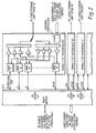
- the MUX/DEMUX and 8 MHZ CT2 interface unit 22 is shown in detail in Figure 2 and the control and association matrix 21 is shown in detail in Figure 3. These are required to ensure that incoming calls from the PSTN are routed to the correct subscriber and that the correct subscriber is billed for each outgoing call.
- the operation and construction of these arrangements will be fully appreciated from the drawings by those skilled in the art and further explanation of their functionality is therefore believed to be unnecessary.
- the CT2 radio base station unit 18 can serve up to 150 domestic subscribers, and since all subscribers are not likely to be using the system at any one time, 150 public telephone exchange lines need not be provided by the public exchange switch network 15. In fact, in order to provide a reasonable service, as few as 12 to 15 lines may be all that is required in order to facilitate the provision of a reasonable service level.
- the electricity sub-station 14 were arranged to feed electricity to a large number of consumers, it may be required to provide telephone services for more than 150 domestic units which could be the limit of a single CT2 base station unit. In order to satisfy this requirement, however, it would be possible to operate two or more base stations in parallel, each of which would be arranged to use a different HF frequency band, and so if say three different HF frequency bands were used, up to 450 telephone subscribers may be served via the electricity supply conductors associated with a common electricity sub-station.
Landscapes
- Engineering & Computer Science (AREA)
- Signal Processing (AREA)
- Computer Networks & Wireless Communication (AREA)
- Power Engineering (AREA)
- Mobile Radio Communication Systems (AREA)
- Prepayment Telephone Systems (AREA)
Applications Claiming Priority (4)
| Application Number | Priority Date | Filing Date | Title |
|---|---|---|---|
| GB9423701 | 1994-11-24 | ||
| GB9423701A GB9423701D0 (en) | 1994-11-24 | 1994-11-24 | Improvements in or relating to line communication systems |
| GB9425039 | 1994-12-08 | ||
| GB9425039A GB2295521B (en) | 1994-11-24 | 1994-12-08 | Improvements in or relating to line communication systems |
Publications (2)
| Publication Number | Publication Date |
|---|---|
| EP0714193A2 true EP0714193A2 (de) | 1996-05-29 |
| EP0714193A3 EP0714193A3 (de) | 2000-11-22 |
Family
ID=26306032
Family Applications (1)
| Application Number | Title | Priority Date | Filing Date |
|---|---|---|---|
| EP95117235A Withdrawn EP0714193A3 (de) | 1994-11-24 | 1995-11-02 | Verbessertes Telekommunikationssystem über das elektrische Versorgungsnetz |
Country Status (2)
| Country | Link |
|---|---|
| US (1) | US5745552A (de) |
| EP (1) | EP0714193A3 (de) |
Cited By (4)
| Publication number | Priority date | Publication date | Assignee | Title |
|---|---|---|---|---|
| FR2754657A1 (fr) * | 1996-10-15 | 1998-04-17 | Electricite De France | Dispositif d'interfacage d'une liaison bidirectionnelle courants porteurs basse tension / radiofrequence |
| WO1998044651A1 (de) * | 1997-03-27 | 1998-10-08 | Berliner Kraft- Und Licht (Bewag)-Aktiengesellschaft | Verfahren und anordnung zur datenübertragung in niederspannungsnetzen |
| WO2000021211A1 (de) * | 1998-10-01 | 2000-04-13 | Lukanek Frank | Verfahren und anordnung zur datenübertragung über niederspannungsnetze |
| WO2000004523A3 (de) * | 1998-07-16 | 2000-04-27 | Siemens Ag | Verfahren und vorrichtung zum steuern von elektrotechnischen oder elektronischen geräten und einrichtungen über telekommunikationsnetze |
Families Citing this family (3)
| Publication number | Priority date | Publication date | Assignee | Title |
|---|---|---|---|---|
| US5970127A (en) | 1997-10-16 | 1999-10-19 | Phonex Corporation | Caller identification system for wireless phone jacks and wireless modem jacks |
| US6243571B1 (en) * | 1998-09-21 | 2001-06-05 | Phonex Corporation | Method and system for distribution of wireless signals for increased wireless coverage using power lines |
| US6704414B2 (en) | 2001-05-17 | 2004-03-09 | Gemini Industries, Inc. | Telephone line extension |
Family Cites Families (9)
| Publication number | Priority date | Publication date | Assignee | Title |
|---|---|---|---|---|
| US4523307A (en) * | 1982-11-30 | 1985-06-11 | Astech, Inc. | Power line carrier multi telephone extension system for full duplex conferencing and intercom between telephones |
| US5623531A (en) * | 1986-10-22 | 1997-04-22 | Nilssen; Ole K. | Auxiliary power for telephone distribution system |
| US4902123A (en) * | 1987-11-25 | 1990-02-20 | Taunton Technologies, Inc. | Topography measuring apparatus |
| US5066939A (en) * | 1989-10-04 | 1991-11-19 | Mansfield Jr Amos R | Method and means of operating a power line carrier communication system |
| US5051720A (en) * | 1989-11-13 | 1991-09-24 | Secure Telecom, Inc. | Remote control system using power line of remote site |
| US5067817A (en) * | 1990-02-08 | 1991-11-26 | Bauer Associates, Inc. | Method and device for noncontacting self-referencing measurement of surface curvature and profile |
| US5319634A (en) * | 1991-10-07 | 1994-06-07 | Phoenix Corporation | Multiple access telephone extension systems and methods |
| GB9205655D0 (en) * | 1992-03-14 | 1992-04-29 | Roke Manor Research | Improvements in or relating to surface curvature measurement |
| GB9407934D0 (en) * | 1994-04-21 | 1994-06-15 | Norweb Plc | Transmission network and filter therefor |
-
1995
- 1995-11-02 EP EP95117235A patent/EP0714193A3/de not_active Withdrawn
- 1995-11-22 US US08/562,226 patent/US5745552A/en not_active Expired - Fee Related
Cited By (7)
| Publication number | Priority date | Publication date | Assignee | Title |
|---|---|---|---|---|
| FR2754657A1 (fr) * | 1996-10-15 | 1998-04-17 | Electricite De France | Dispositif d'interfacage d'une liaison bidirectionnelle courants porteurs basse tension / radiofrequence |
| WO1998017013A1 (fr) * | 1996-10-15 | 1998-04-23 | Electricite De France (Service National) | Dispositif d'interfaçage d'une liaison bidirectionnelle courants porteurs basse tension/radiofrequence |
| US6069556A (en) * | 1996-10-15 | 2000-05-30 | Electricite De France | Interface device bi-directional connection of currents carrying low voltage/radiofrequency |
| WO1998044651A1 (de) * | 1997-03-27 | 1998-10-08 | Berliner Kraft- Und Licht (Bewag)-Aktiengesellschaft | Verfahren und anordnung zur datenübertragung in niederspannungsnetzen |
| US6507573B1 (en) | 1997-03-27 | 2003-01-14 | Frank Brandt | Data transfer method and system in low voltage networks |
| WO2000004523A3 (de) * | 1998-07-16 | 2000-04-27 | Siemens Ag | Verfahren und vorrichtung zum steuern von elektrotechnischen oder elektronischen geräten und einrichtungen über telekommunikationsnetze |
| WO2000021211A1 (de) * | 1998-10-01 | 2000-04-13 | Lukanek Frank | Verfahren und anordnung zur datenübertragung über niederspannungsnetze |
Also Published As
| Publication number | Publication date |
|---|---|
| US5745552A (en) | 1998-04-28 |
| EP0714193A3 (de) | 2000-11-22 |
Similar Documents
| Publication | Publication Date | Title |
|---|---|---|
| US5133001A (en) | Radiotelephone system in the form of a private branch exchange | |
| US5995828A (en) | Portable handy phone system | |
| EP0872111B1 (de) | Persönliches hauskommunikationssystem | |
| US5473669A (en) | Method for controlling a mobile IVD system having a plurality of personal stations (PSs) | |
| US3980831A (en) | Data switching system | |
| EP0239093A2 (de) | Selektiv in Voll-duplex- und Halb-duplex-Mode arbeitendes Radiotelefonsystem mit mehreren Eingängen | |
| JP2000507417A (ja) | 移動電話呼用の代替ルーティングシステム | |
| US5745552A (en) | Line communication systems incorporating mains electricity conductors for communications | |
| US20020049036A1 (en) | Wireless phone/data jack using 49 mhz rf technology | |
| WO1997045994A1 (en) | Telephone system | |
| US6138015A (en) | Multi-cell radio system with PBX periphery assemblies | |
| WO1997006611A1 (en) | A wireless multi-cell radio telecommunication system | |
| RU98103392A (ru) | Система беспроводной многоячеистой радиосвязи | |
| GB2295521A (en) | Improvements in or relating to line communication systems | |
| GB2251359A (en) | Telephone system with subscriber paging | |
| EP0932968B1 (de) | Aufbau einer telekommunikationsverbindung | |
| US20020064183A1 (en) | Arrangement and method relating to data-, and telecommunication | |
| JP3332685B2 (ja) | Catv網を用いた簡易型携帯電話システム | |
| WO1998020663A2 (en) | Establishing a telecommunication connection | |
| JPS5881349A (ja) | 過疎地用無線電話交換方式 | |
| KR100306474B1 (ko) | 더블유엘엘멀티라인모듈 | |
| WO1998020662A9 (en) | Establishing a telecommunication connection | |
| AU753764B2 (en) | Telephone system | |
| KR100350224B1 (ko) | 근거리 통신망과 전화 장치를 결합한 통신 시스템 | |
| JP3301302B2 (ja) | 通信システム |
Legal Events
| Date | Code | Title | Description |
|---|---|---|---|
| PUAI | Public reference made under article 153(3) epc to a published international application that has entered the european phase |
Free format text: ORIGINAL CODE: 0009012 |
|
| AK | Designated contracting states |
Kind code of ref document: A2 Designated state(s): DE ES FR IT |
|
| 17P | Request for examination filed |
Effective date: 19961002 |
|
| RAP1 | Party data changed (applicant data changed or rights of an application transferred) |
Owner name: MARCONI COMMUNICATIONS LIMITED |
|
| PUAL | Search report despatched |
Free format text: ORIGINAL CODE: 0009013 |
|
| AK | Designated contracting states |
Kind code of ref document: A3 Designated state(s): DE ES FR IT |
|
| STAA | Information on the status of an ep patent application or granted ep patent |
Free format text: STATUS: THE APPLICATION HAS BEEN WITHDRAWN |
|
| 18W | Application withdrawn |
Withdrawal date: 20001220 |