EP0714687B1 - Verfahren und Vorrichtung zum Entwässern von Schlämmen und ähnlichen Substanzen - Google Patents
Verfahren und Vorrichtung zum Entwässern von Schlämmen und ähnlichen Substanzen Download PDFInfo
- Publication number
- EP0714687B1 EP0714687B1 EP95118363A EP95118363A EP0714687B1 EP 0714687 B1 EP0714687 B1 EP 0714687B1 EP 95118363 A EP95118363 A EP 95118363A EP 95118363 A EP95118363 A EP 95118363A EP 0714687 B1 EP0714687 B1 EP 0714687B1
- Authority
- EP
- European Patent Office
- Prior art keywords
- sludge
- chamber
- filter
- pressure
- sludge chamber
- Prior art date
- Legal status (The legal status is an assumption and is not a legal conclusion. Google has not performed a legal analysis and makes no representation as to the accuracy of the status listed.)
- Expired - Lifetime
Links
- 239000010802 sludge Substances 0.000 title claims abstract description 245
- 238000000034 method Methods 0.000 title claims abstract description 34
- 239000000126 substance Substances 0.000 title claims abstract description 8
- 230000008569 process Effects 0.000 title abstract description 9
- 230000002706 hydrostatic effect Effects 0.000 claims abstract description 42
- 239000012065 filter cake Substances 0.000 claims abstract description 22
- 239000000706 filtrate Substances 0.000 claims description 20
- 238000007789 sealing Methods 0.000 claims description 11
- 238000005452 bending Methods 0.000 claims description 6
- 238000006073 displacement reaction Methods 0.000 claims description 6
- 238000001914 filtration Methods 0.000 claims description 5
- 230000007423 decrease Effects 0.000 claims description 2
- 230000003247 decreasing effect Effects 0.000 claims 2
- 241000282472 Canis lupus familiaris Species 0.000 claims 1
- 238000004891 communication Methods 0.000 claims 1
- 210000003414 extremity Anatomy 0.000 claims 1
- 210000003141 lower extremity Anatomy 0.000 claims 1
- 238000011144 upstream manufacturing Methods 0.000 claims 1
- XLYOFNOQVPJJNP-UHFFFAOYSA-N water Substances O XLYOFNOQVPJJNP-UHFFFAOYSA-N 0.000 abstract 2
- 230000000717 retained effect Effects 0.000 abstract 1
- 238000004804 winding Methods 0.000 description 20
- 238000005406 washing Methods 0.000 description 7
- 230000008901 benefit Effects 0.000 description 6
- 238000010276 construction Methods 0.000 description 6
- 239000000314 lubricant Substances 0.000 description 6
- 238000005189 flocculation Methods 0.000 description 5
- 230000016615 flocculation Effects 0.000 description 5
- 230000000903 blocking effect Effects 0.000 description 4
- 238000013461 design Methods 0.000 description 4
- 239000000969 carrier Substances 0.000 description 3
- 238000004140 cleaning Methods 0.000 description 3
- 230000005484 gravity Effects 0.000 description 3
- 239000000463 material Substances 0.000 description 3
- 239000012528 membrane Substances 0.000 description 3
- 238000011161 development Methods 0.000 description 2
- 238000007599 discharging Methods 0.000 description 2
- 239000008394 flocculating agent Substances 0.000 description 2
- 238000002347 injection Methods 0.000 description 2
- 239000007924 injection Substances 0.000 description 2
- 238000009434 installation Methods 0.000 description 2
- 230000002441 reversible effect Effects 0.000 description 2
- 239000000725 suspension Substances 0.000 description 2
- 230000009471 action Effects 0.000 description 1
- 230000001680 brushing effect Effects 0.000 description 1
- 230000008859 change Effects 0.000 description 1
- 238000006243 chemical reaction Methods 0.000 description 1
- 230000007547 defect Effects 0.000 description 1
- 238000010586 diagram Methods 0.000 description 1
- 238000011038 discontinuous diafiltration by volume reduction Methods 0.000 description 1
- 238000009826 distribution Methods 0.000 description 1
- 230000000694 effects Effects 0.000 description 1
- 230000002349 favourable effect Effects 0.000 description 1
- 238000012423 maintenance Methods 0.000 description 1
- 238000004519 manufacturing process Methods 0.000 description 1
- 238000012986 modification Methods 0.000 description 1
- 230000004048 modification Effects 0.000 description 1
- 239000004033 plastic Substances 0.000 description 1
- 238000007639 printing Methods 0.000 description 1
- 230000000750 progressive effect Effects 0.000 description 1
- 238000005086 pumping Methods 0.000 description 1
- 230000009467 reduction Effects 0.000 description 1
- 238000004904 shortening Methods 0.000 description 1
- 230000001360 synchronised effect Effects 0.000 description 1
- 238000004065 wastewater treatment Methods 0.000 description 1
Images








Classifications
-
- B—PERFORMING OPERATIONS; TRANSPORTING
- B01—PHYSICAL OR CHEMICAL PROCESSES OR APPARATUS IN GENERAL
- B01D—SEPARATION
- B01D25/00—Filters formed by clamping together several filtering elements or parts of such elements
- B01D25/12—Filter presses, i.e. of the plate or plate and frame type
- B01D25/127—Filter presses, i.e. of the plate or plate and frame type with one or more movable filter bands arranged to be clamped between the press plates or between a plate and a frame during filtration, e.g. zigzag endless filter bands
- B01D25/1275—Filter presses, i.e. of the plate or plate and frame type with one or more movable filter bands arranged to be clamped between the press plates or between a plate and a frame during filtration, e.g. zigzag endless filter bands the plates or the frames being placed in a non-vertical position
-
- B—PERFORMING OPERATIONS; TRANSPORTING
- B01—PHYSICAL OR CHEMICAL PROCESSES OR APPARATUS IN GENERAL
- B01D—SEPARATION
- B01D25/00—Filters formed by clamping together several filtering elements or parts of such elements
- B01D25/12—Filter presses, i.e. of the plate or plate and frame type
- B01D25/172—Plate spreading means
-
- B—PERFORMING OPERATIONS; TRANSPORTING
- B01—PHYSICAL OR CHEMICAL PROCESSES OR APPARATUS IN GENERAL
- B01D—SEPARATION
- B01D25/00—Filters formed by clamping together several filtering elements or parts of such elements
- B01D25/28—Leaching or washing filter cakes in the filter handling the filter cake for purposes other than regenerating
- B01D25/282—Leaching or washing filter cakes in the filter handling the filter cake for purposes other than regenerating for drying
- B01D25/285—Leaching or washing filter cakes in the filter handling the filter cake for purposes other than regenerating for drying by compression using inflatable membranes
-
- B—PERFORMING OPERATIONS; TRANSPORTING
- B01—PHYSICAL OR CHEMICAL PROCESSES OR APPARATUS IN GENERAL
- B01D—SEPARATION
- B01D25/00—Filters formed by clamping together several filtering elements or parts of such elements
- B01D25/28—Leaching or washing filter cakes in the filter handling the filter cake for purposes other than regenerating
- B01D25/282—Leaching or washing filter cakes in the filter handling the filter cake for purposes other than regenerating for drying
- B01D25/287—Leaching or washing filter cakes in the filter handling the filter cake for purposes other than regenerating for drying by compression using pistons
-
- B—PERFORMING OPERATIONS; TRANSPORTING
- B01—PHYSICAL OR CHEMICAL PROCESSES OR APPARATUS IN GENERAL
- B01D—SEPARATION
- B01D25/00—Filters formed by clamping together several filtering elements or parts of such elements
- B01D25/30—Feeding devices ; Discharge devices
-
- B—PERFORMING OPERATIONS; TRANSPORTING
- B01—PHYSICAL OR CHEMICAL PROCESSES OR APPARATUS IN GENERAL
- B01D—SEPARATION
- B01D25/00—Filters formed by clamping together several filtering elements or parts of such elements
- B01D25/32—Removal of the filter cakes
-
- B—PERFORMING OPERATIONS; TRANSPORTING
- B01—PHYSICAL OR CHEMICAL PROCESSES OR APPARATUS IN GENERAL
- B01D—SEPARATION
- B01D2201/00—Details relating to filtering apparatus
- B01D2201/20—Pressure-related systems for filters
- B01D2201/202—Systems for applying pressure to filters
Definitions
- the invention relates to a method for dewatering Sludges and similar substances, in which the sludge underneath Closed pressure having at least one filter surface Mud chamber fed and in the mud chamber a hydrostatic drainage Pressure is built up, after drainage to The sludge chamber is removed from the filter cake opened and the filter surfaces with the filter cake from the Mud chamber to be moved out.
- sludges and similar substances for example those in wastewater treatment plants Sludge, after adding organic or inorganic flocculants or filter aids in chamber filter presses to drain.
- the sludge is closed in all-round filter chambers fed and by means of pumps the medium to be dewatered pumped with high pressure until the desired one Dry matter content is reached. That in the one to be drained Filtrate contained in this is by the dividing walls of individual filter material Filter chambers discharged.
- Disadvantage of known chamber filter presses this type and the corresponding procedure when dewatering it is that at very high technical Effort the efficiency with which the pressure on the to draining substance is transferred from chamber to chamber decreases in the conveying direction.
- EP-A-0 407 884 proposed a pump type in which two opposing Piston pumps are used.
- the pressure stroke one pump start before the other pump begins its pressure stroke has ended in order on the discharge side of the two piston pumps an essentially constant pressure level to reach.
- this known pump also runs over a extended period continuously.
- EP-A-0 397 082 a method and a filter press for Dewatering of mud and similar substances known at which the sludge in the filter press in a closed on all sides Sludge chamber is fed by a pump and a hydrostatic pressure of definable levels is built up becomes. Then the sludge chamber is opposite the pump separated and the volume of the sludge chamber reduced to to generate a mechanical drainage pressure.
- the pressure is also built up by a common pump, which are hydrostatic throughout the construction phase Pressure must run continuously. This is one gentle treatment of the flocculated sludge unfortunately not possible.
- mechanical drainage pressure generated by a pressure membrane In this known filter press mechanical drainage pressure generated by a pressure membrane.
- the invention is based on this prior art based on the task of a completely new drainage process and a suitable one for performing this method To create device in which during the construction of the hydrostatic pressure does not destroy the flocculation of the sludge and with which with little technical effort a significantly improved efficiency and beyond a significantly improved throughput is guaranteed.
- this is Task essentially solved in that the sludge in at least one connected to the sludge chamber Intermediate container is inserted that the intermediate container absorbs an amount of mud that is about twice the Volume of the sludge chamber corresponds to that after that Sludge feed to the intermediate tank is separated that subsequently which the mud chamber by positive displacement a sludge volume is filled from the intermediate tank, that after filling the sludge chamber the hydrostatic Pressure by positive displacement of the volume of the sludge chamber exceeding part of the second filling of the intermediate container is generated and that depending on the specific Dewatering behavior of the sludge is a hydrostatic pressure is generated from about 5 to 10 bar.
- the sludge is fed to the intermediate tank via an expansion tank, which continuously with Sludge is filled, in the expansion tank at the same time the sludge is pre-dewatered and wherein the sludge enters the sludge chamber at multiple points simultaneously from one corresponding to the number of these points Number of intermediate containers is initiated.
- the advantage of a quasi-continuous Working method achieved by at least the sludge feed can be done continuously.
- Another object of the invention is a device for Carrying out the method described above with at least a closed sludge chamber on the side, which filter surfaces and has a sludge inlet which is connected to a a hydrostatic filtration pressure generating device is connected, the filter surfaces between relative mutually movable pressure plates are arranged, and the Filter surfaces to discharge the filter cake after opening the pressure plates with respect to the sludge chamber are formed, the basis of the invention
- the Device for generating the hydrostatic filtration pressure is designed as one or more intermediate containers, that the intermediate container as a piston-cylinder unit with a Cylinder housing and a piston displaceable therein as well a drive for the piston is formed, each piston cylinder unit one mud inlet and one with the Sludge chamber has connected sludge outlet, that alternately actuated at the sludge inlet and at the sludge outlet Locking and control valves are provided and that Volume of the intermediate container or containers about twice the volume corresponds to the sludge
- the sludge chamber has several sludge inlets, that a corresponding number of intermediate containers is provided in which each sludge inlet through a separate Connection line with one of the mud inlets of the Mud chamber is connected and that the locking and control valves are designed as ball valves.
- This will Mud actually evenly at several points at the same time introduced into the sludge chamber, and the hydrostatic Drainage pressure also uniform and at the same time built up from several points in the mud chamber.
- the flocculated sludge is conveyed on very gently, by such ball valves the full line cross section form and therefore no buckling or for the flow Offer defects where the flakes are destroyed can.
- the filter surfaces can be pushed back and forth in a straight line Filter tapes formed. This will make the process the elaborate discharge of the mud cake in known Chamber filter presses avoided by the filter belts after dewatering, the press cake obtained laterally can drive out of the open sludge chamber, after which then a simple cleaning of the filter cloths when it can return while this is done again can be driven into the sludge chamber.
- the sludge chamber through a upper and lower filter surface is formed between them a flexible seal surrounding the sludge chamber is arranged is that the seal is attached to a subframe that the subframe can be moved on the upper by means of carriers Pressure plate is suspended and that the mud chamber one has an oval outline.
- each filter surface on a bearing plate which is provided with channels open to the filter surface is that the sludge chamber with the filter surfaces opposite the horizontal is inclined in the longitudinal direction is that the slope of the filter surfaces falls by about Corresponds to 10 ° and that the channels to the main axis of the sludge chamber are formed in parallel. This will make a quick and safe discharge of the resulting from the drainage Filtrate on both the outside of the filter surfaces the top as well as the bottom of the mud chamber reached.
- the lower pressure plate is supported on high pressure generators, by means of which the volume of the sludge chamber Reaching the hydrostatic drainage pressure for generation an additional mechanical drainage pressure is scalable.
- the lower pressure plate as a hydraulic bed is formed by side by side a number of high pressure generators across the length and / or width of the bottom Pressure plate are distributed, and that the high pressure generator in several parallel rows within the oval circumference of the sludge chamber are arranged, the High pressure generator of adjacent rows offset from one another are.
- the high-pressure generators can laterally outside the area of the sludge chamber.
- the high-pressure generators can laterally outside the area of the sludge chamber.
- Hydraulic are advantageously used as high-pressure generators Single cylinder used.
- This embodiment has the advantage that the enormous Pressures with comparatively inexpensive high pressure generators can be achieved and that at the same time bending stresses be avoided because the high pressure is generated where it is is needed, namely in the area of the area Mud chamber itself.
- the closed position of the sludge chamber is mechanical locked, advantageously for locking a pawl assembly acting on the upper pressure plate is provided.
- sludge chambers are arranged one above the other and for respective manufacture of another sludge chamber is between an intermediate plate for the upper and lower pressure plates provided, which depending on their top and bottom has a bearing plate and a filter belt each, furthermore an auxiliary frame with gasket is hung on the underside is.
- This type of construction can be in the form of a modular construction in accordance with the present Throughput requirements any number of sludge chambers.
- a pre-drainage device in front of the intermediate container or containers a pre-drainage device is provided in front of the intermediate container or containers is the sludge outlet with the sludge inlet of the piston cylinder units is connected that the pre-drainage device is designed as a surge tank, the inlet is connected to a continuous sludge supply and that the pre-dewatering device one or more in the filter body immersed in the sludge of the expansion tank has, which are provided with a filtrate outlet.
- the filter basket is arranged stationary and that one or more about the height of the filter basket reaching brushes are provided, which on the Run around the filtrate side of the filter basket. Because of the slowly circulating Brushing will change the drainage behavior of the Mud improved considerably without the flocculation being destroyed because the brushes are located on the filtrate side.
- the invention can be developed by that between the pressure plates and / or intermediate plates the height of the sludge chamber provided stops are and that the stops according to the volume reduction the sludge chamber (or the associated reduction the height of the sludge chamber) compressible and resilient are trained.
- This feature is particularly related with the mechanical locking of the closed Position of the sludge chambers is an advantage, as this makes the closed Position is clearly defined.
- the invention further relates to a seal for lateral Sealing a volume that can be reduced in the vertical direction Pressure chamber, as detailed in these Seal related claims is characterized.
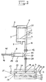
- the device shown there, generally designated 1 consists of three main components, namely a pre-drainage stage 2, an intermediate container 3 and one Filter press 4.
- the pre-dewatering stage 2 consists of an expansion tank 5, which is connected to a continuous sludge feed 6 connected.
- a filter basket 7 arranged, which has a filtrate outlet 8.
- the filter basket 7 is in the expansion tank fed sludge 9 immersed.
- the expansion tank 5 has one at its lower end Sludge outlet line 10, which with the sludge inlet 11 of the intermediate container 3 is connected.
- a blocking or control valve 12 is provided, through which the supply of sludge to the intermediate tank 3 can be interrupted.
- the intermediate container 3 is in the manner of a large injection syringe formed and exists as a piston-cylinder unit from a cylinder housing 13 and a displaceable therein Piston 14, which with its piston rod a drive 15 is connected, which in the embodiment by a hydraulic piston or pneumatic piston 16 is formed.
- the sludge outlet 17 of the intermediate container 3 is via a Line 18 with the sludge inlet 19 of a sludge chamber 20th connected to the filter press 4, being in line 18 further blocking or control valve 21 is provided.
- the Mud chamber 20 of the filter press 4 is between an upper one Pressure plate 22 and a lower pressure plate 23 arranged, which individually or both in the vertical direction can be designed to be movable.
- the sludge chamber 20 is covered by an upper filter surface 24 and a lower filter surface 25, which consists of a upper filter belt 26 and a lower filter belt 27, the straight back and forth in the horizontal direction are movable. Is between the filter belts 26 and 27 a seal 28 surrounding the sludge chamber 20 provided which seals when the sludge chamber is closed bears against the two filter bands 26 and 27. Above of the upper filter belt 26 and below the lower filter belt 27 is between the pressure plates 22, 23 and the filter belts 26, 27 each have a bearing plate 31 arranged, which open channels on the side of the filter belts 26, 27 or has grooves that are used to remove the through the filter belts leaking filtrate serve. This will continue below with reference to the various embodiments the device according to the invention explained in more detail.
- the continuously fed sludge is in the Expansion tank 5 of a continuous pre-drainage exposed to the effects of gravity, the resulting Filtrate discharged from the filtrate outlet 8 of the filter basket 7 becomes. In this way, the mud 9 on the Sludge outlet line 10 already has a dry matter content from about 20%.
- a sludge supply is added to the Intermediate container 3 transferred by the control valve 12, which is preferably designed as a ball valve, opened and through the piston 14 from its forward position the drive 15 is moved to the rear.
- This filling of the intermediate container 3 can be extremely gentle and done slowly so that the flocculation of the sludge is preserved remains.
- the intermediate container 3 takes up a sludge supply which is about one and a half times the volume of the Mud chamber 20 corresponds.
- the control valve 12 is closed and then opened the control valve 21. After that the sludge volume contained in the intermediate container 3 positively displaced from the intermediate container in which the piston 14 moved by the drive 15 to its front position becomes.
- the control valve 21 After reaching the desired hydrostatic pressure in the sludge chamber 20, the control valve 21 is closed again and by opening the control valve 12 the Intermediate container 3 is completely filled again and is ready for the next cycle. At the same time, through appropriate Movement of the pressure plates 22 and / or 23 the Mud chamber 20 opened and the mud cake produced by moving the filter belts 26, 27 horizontally discharged from the sludge chamber 20.
- the filter belts 26 and 27 are cleaned by both side wash nozzles while this again be moved back to their starting position, after which the Mud chamber is closed again and what the top described cycle can be repeated.
- FIG. 2 corresponds in its technical details of the embodiment according to FIG. 1, so that the same reference numerals for the same or equivalent parts were used. Only the filter press 4 is different from the embodiment of FIG. 1 designed to carry out an additional To enable process step.
- the bottom one Pressure plate 23 mounted on a hydraulic bed 32, which of a plurality of acting on the pressure plate 23 High pressure generators 33 exists.
- FIG. 3 corresponds essentially the embodiment of FIG. 2 with the difference that on the one hand in several sludge chambers arranged one above the other 20 is drained at the same time, and that the Mud at several points in the mud chamber at the same time 20 from a corresponding number of intermediate containers is fed, and consequently also the hydrostatic Printing based on several points in each Mud chambers 20 is built.
- the constructive Details will be given on the below Description of the various embodiments of the invention Device referred. According to the representation Fig. 3 were only the corresponding to the number of Mud chambers reproduced individual parts on the reference number provided with a dash, the upper one Mud chamber 20 supplying intermediate container 3 in dashed lines Lines are illustrated.
- the embodiment according to FIG. 4 essentially corresponds Details of the embodiment of FIG. 2, so that again the same for the same or equivalent parts Reference numerals were used. Only with this Embodiment the mud chamber 20 with the corresponding Filter surfaces 25, 26 inclined to the horizontal arranged, which serves that from the filter belts 26th and 27 filtrate emerging at the top and bottom, which is in the open channels of the bearing plates 31 continuously collects to be removed by gravity.
- a filter basket 7 is provided on the outside of the Filter basket 7, a washing device 38 is provided, which consists of washing nozzles 38a and at least one over the Height of the filter basket 7 reaching brush 38b.
- a scraper on the inside of the filter basket 7 35 provided, which over a rod 35a the height of the filter basket 7 can be moved up and down is.
- the washing device 38 and the scraper 35 existing unit is driven by a drive 34, so that by rotating this unit and the up and Downward movement of the scraper 35 both the outside as well as the inside of the filter basket, which is cylindrical trained, can be cleaned thoroughly.
- the scraper 35 mainly serves the ground and periodically clean the filter basket sludge outlets.
- the drive 34 by an electric motor 35 and a spur gear 36 formed.
- the brushes 35b one of which is preferred provided three pieces distributed around the circumference of the filter basket are slowly running around the filter basket um, with the bristles repeatedly in the filter openings enter and activate the drainage.
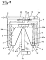
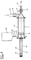
- the continuous sludge supply a mixer 40 formed by a continuous running pump is fed, and which by a Motor 41 is driven and the mud continuously in feeds the expansion tank 5.
- the mixer 40 is standing arranged and mixes the sludge with the flocculant, which is added by the metering device 40B becomes.
- the mixer 40 has a mixing and Screw conveyor 40A, which is schematic in Figure 5 is shown.
- a number of sludge outlets 10A provided over the Mud outlet lines 10 with the mud inlets 11 of the Intermediate container 3 are connected.
- the number of sludge outlets 10A, the sludge outlet lines 10 and the intermediate tank 3 corresponds to the number of sludge inlets 19 of the sludge chamber 20, as best seen in FIG. 7 is.
- the sludge chamber 20 has a total of eight Sludge inlets 19, which via eight lines 18 each are individually connected to eight intermediate containers 3.
- the eight intermediate containers 3 have a total volume, which is one and a half times the volume of the sludge chamber 20 corresponds.
- the intermediate container is 3 from the basic principle like a large injection syringe built up by a piston-cylinder unit 13, 14 is formed.
- the sludge outlet line 10 At the front end of the cylinder 13 of the intermediate container 3 is the with the sludge outlet line 10 in Connected sludge inlet 11 is provided, in front of which the blocking and control valve 12 is arranged.
- Locking and control valve 12 as electrical or hydraulic Controlled ball valve designed to be as gentle as possible Conveying the flocculated sludge, i.e. without it Ensure cross-sectional changes or disruptions.
- the sludge outlet 17 of the intermediate container 3 is provided, which with the line 18 is connected and before which the second blocking and control valve 21 is arranged.
- the Locking and control valve 21 is also electrical or hydraulically controlled ball valve.
- the piston 14 can be moved back and forth in the cylinder 13 arranged by which the positive repression of the sludge volume in the intermediate container 3.
- the piston 14 has a drive 15, which by a hydraulic or pneumatic piston 16 is formed, the is slidably disposed in a cylinder 117 and over its piston rod 116 is connected to the piston 14.
- a lubricant container 103 is provided, which via a Line 104 connected to an inlet 105 in the cylinder 13 is located on the back of the piston 14.
- a valve 106 is additionally provided for maintenance work.
- the arrangement is such that when the Piston 14 is moved forward by the drive 15 and displaces the sludge volume from the intermediate tank, 14 lubricant simultaneously on the back of the piston is sucked out of the lubricant container 103, and thus the cylinder 13 is constantly lubricated. If the control valve 12 opened and the control valve 21 is closed and the piston 14 is moved rearward and out of the expansion tank 5 sucks in a new volume of sludge that behind the piston 14 in the cylinder 13 Lubricant displaced back into the lubricant reservoir 103.
- FIGS. 5 to 8 The filter press 4 illustrated in FIGS. 5 to 8 is further below in connection with Figure 5 With reference to Figures 16 and 17 described in more detail.
- Figures 10 to 15 are details of the Pre-dewatering stage 2 and the intermediate containers 3 according to 5 to 9 associated filter press 4 shown, whose basic structure corresponds to the procedure according to FIG. 1, however, in Figures 14 and 15 the technical Possibilities are shown, the number of sludge chambers 20 to enlarge.
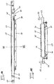
- Figures 10 to 13 show the filter press 4 in the two basic positions, namely the open position 10 and 11 position for discharging the filter cake and cleaning the filter surfaces and the closed Position according to Figures 12 and 13, in which the Sludge chamber filled and drainage under hydrostatic Pressure according to the procedure according to FIG. 1 is carried out.
- FIGS Filter press the upper pressure plate 22 and the lower pressure plate 23, with the upper pressure plate 22 opposite the lower pressure plate 23 can be raised by lifting cylinder 42 (Fig. 11) and can be lowered.
- the bearing plates preferably consist of a low-friction plastic, because on these bearing plates 31 which form the upper and lower filter surfaces 24 and 25, respectively Slide filter belts 26 and 27.
- the filter belts 26 and 27 are in the illustrated embodiment horizontally movable back and forth.
- the upper filter belt 26 is at both ends each held by a reversible winding drive 44, so that the filter belt 26 once on the left winding drive 43 is wound up, i.e. the filter surface 24 in the Mud chamber 20 is moved into it, and in the reverse Fall the filter belt 26 on the right winding drive 44 is wound up, i.e. the filter surface 24 from the Mud chamber 20 is moved out.
- Filter belt 26 still guided around a deflection roller 46, which a scraper 47 is assigned, which may be on Filter belt 26 adhering residues of the filter cake when discharging strips off.
- the lower filter band 27 is also corresponding the upper filter belt 26 of two winding drives 50 and 51, which are synchronous with the winding drives 43 and 44 are operated.
- the lower filter belt 27 is also around a deflection roller 52 performed with a scraper 53.
- the mud inlets 19 are in the Mud chamber 20, which has a corresponding number of Lines 18 with the corresponding number of Intermediate containers 3 are connected as horizontal, slot-like openings in the surrounding the sludge chamber 20 Seal 28 formed.
- the sludge chamber 20 mechanically in the closed position be locked so that it is not necessary a larger or corresponding to the drainage pressure Build up back pressure.
- the invention Filter press 4 a pawl device 54 provided which consists of a number of pivotable Pawls 55 exist on a common axis 56 are stored along both side edges of the filter press 4, each of the axes via pneumatic cylinders 57 and one Lever drive 58 between the open position according to FIG. 10 and 11 and the locked position shown in FIG. 12 and 13 is pivotable.
- the filter press 4 preferably set up such that the sludge chamber 20th is inclined to the horizontal, the inclination corresponds approximately to a gradient of the filter surfaces 24 and 25 of 5 °. This will ensure that the upper filter surface 24 in the channels of the bearing plate 31st filtrate entering the drainage due to the gradient is dissipated.
- the sludge chamber through which the sludge chamber 20 surrounding, flexible seal 28 and that enclosed by this Area of the filter belts 26 and 27 formed.
- the details of the seal 28 itself will be discussed below discussed in more detail.
- the Seal 28 carried by an auxiliary frame 60, which on and movable from the top by push rods 61 Pressure plate is suspended. This type of suspension is useful so that the sludge chamber 20 is closed securely can be when the upper pressure plate 22 toward the lower pressure plate 23 until the stops are reached 59 is lowered by relieving the lifting cylinder 42.
- the Push rods 61 thus form drivers 62, which are limited Relative movement between the upper pressure plate 22 and allow the seal 28.
- FIGS. 14 and 15 show a module-like component in FIG Form of an intermediate plate 63, by means of which the number of stacked sludge chambers 20 in the Filter press 4 according to Figures 10 to 13 and also in the embodiments described below can increase arbitrarily.
- one Intermediate plate 63 according to Figures 14 and 15 between the upper pressure plate 22 and the lower pressure plate 23 is formed one more sludge chamber 20 each Use such an intermediate plate on both sides the same pressure is loaded, because in the superimposed Sludge chambers 20 built the same drainage pressure its carrier plate 64 can be made of, for example a light grid, because it is only on one certain compressive strength arrives.
- each has Intermediate plate on each of its top and bottom Bearing plates 31 on which an upper filter belt 65 or a lower filter belt 66 slides.
- Corresponding intermediate plate 63 for the filter tapes Winding drives 67, 68, 69 and 70 with the associated deflection rollers, Wipers and a washing device provided which are identical to the details described above are with reference to the upper and lower Pressure plate 22 and 23 have been described.
- the winding drives and the associated auxiliary devices for the two filter belts 65 and 66 in the intermediate plate 63 arranged.
- Seal 28 hangs with its subframe 60 in drivers 62.
- the stops 59 are provided on the underside of the intermediate plate 63 .
- FIGS of the device according to the invention Another practical embodiment is shown in FIGS of the device according to the invention, how they are used to carry out the method according to FIG. 2 to 4 is particularly useful according to FIG. 3.
- 16 shows a side sectional view of FIG Filter press 4, the pre-dewatering device and the intermediate containers 3 corresponding to FIGS. 5 to 9 can be trained. 16 are further separated through the lines XIX, XXII and XXV the different Operating states and the corresponding different positions of the individual components shown.
- the lower pressure plate is 23 also designed to be movable and is used after reaching the desired hydrostatic drainage pressure, which by the volume advance by means of the intermediate container 3 is set, an additional mechanical Drainage pressure by reducing the amount of To produce sludge chambers 20.
- the lower pressure plate 23 to a number of those mentioned above High pressure generator 33 stored, which as in the embodiment 16 to 27 either in two rows arranged along the longitudinal edges of the lower pressure plate 23 can be, or which, as described above, as a hydraulic Bed 32 can be formed.
- each mud chamber 20 is in the Outline preferably oval, so that no corners and The like arise with corresponding pressure peaks.
- FIG. 19 also shows details of the installation of an intermediate plate 63 can be seen.
- the intermediate plate is 63 by means of upper drivers 71 on the upper pressure plate 22 suspended and by lower drivers 72, which are connected to the lower pressure plate 23.
- This type of installation allows, as can be seen from the following Description of how it still works reveals the different Relative movements of the individual parts to each other.
- the stops 59 also the modified Requirements of this embodiment are adapted by the stops 59 have an upper part 73, which is either resiliently pushable into the stop 59 or Forms part of a correspondingly lowerable hydraulic cylinder.
- Figures 19 to 22 show the open state of the Mud chambers 20, the lifting cylinder 42 the upper Have raised pressure plate 22 upwards.
- the pawls 55 are opened by the pneumatic cylinder 57 have been pivoted into the open position.
- the high pressure generator 33 were relieved at the same time, so that in the state shown in Fig. 19, the lower Pressure plate 23 has also lowered, which supports it is that this is the reaction forces of the lifting cylinders 42 records.
- the stops 59 are also relieved in this state and assume the position shown in Fig. 21, in which the tops 73 the height of the closed sludge chambers define.
- the filter press 43 is ready, the in filter cake 94 formed in a previous cycle to discharge the mud chambers 20.
- Winding drives 44, 51 and 67, 68 actuated while the winding drives assigned to the other end of the filter press 43, 50 and 67, 69 are released.
- the filter tapes 26, 27 and 65, 66 synchronously from the sludge chambers 20 are pulled out and after dropping the filter cake 74 the winding drives 44, 51 and 68, 70 released and the Winding drives 43, 50, 67 and 69 actuated so that the filter belts 26, 27 and 65, 66 turn synchronously into the Sludge chambers 20 are retracted.
- cleaning of the filter belts by means of the washing nozzles 49.
- the filter press 4 is at the end of this process again in the state shown in FIG. 19, but in the Mud chambers 20 no filter cake 94 is included.
- the filter press 4 is in the state according to 22 to 24 transferred, the mud chambers 20 to be closed.
- the lifting cylinders 42 relieves pressure and lowers while taking the seals with them 28 and the intermediate plate 63 on the upper pressure plate 22 the lower pressure plate 23.
- the high pressure generator 33 remain in the relieved state.
- the upper pressure plate 22 and the intermediate plate 63 are lowered until it engages with the upper parts 73 of the stops 59 arrive.
- the Pawls 55 by actuating the pneumatic cylinders 57 locked and are in the position shown in Fig. 22 panned, in which the distance between the upper Pressure plate 22 and the lower pressure plate 23 mechanically fixed and fixed by the stops 59.
- the seals 28 of the sludge chambers 20 pressed tightly together, the upper mud chamber 20th above and below through the filter belt 26 and the filter belt 65 of the intermediate plate 63 is closed, and the lower Mud chamber 20 above and below through the lower filter belt 66 of the intermediate plate 63 and the filter belt 27 of the lower one Pressure plate 23 is closed.
- the sludge contains it Filtrate out through the filter belts 26, 27 and 65, 66 pressed into the channels in the bearing plates 31 and is due to the parallel to the main axis of the sludge chamber 20 Arrangement of channels 75 and due to the slope against the discharge direction on the front side from the Filter press 4 led out.
- the high pressure generator 33 are operated to mechanically the volume of the sludge chambers 20 in vertical direction and thus possibly one significantly above the hydrostatic drainage pressure additional mechanical drainage pressure to create.
- This process is in the figures 25 to 27 shown, the high pressure generator 33 in their fully extended position are illustrated, in which the highest drainage pressure was reached.
- the pawls 55 are still closed, and it became the lower pressure plate 23 by the High pressure generator 33 up against the upper pressure plate 22 moves.
- the tops were made during this process 73 of the stops 59 pressed into the stops 59, to reduce the distance between the bottom Pressure plate 23 and the intermediate plate 63 and the To enable intermediate plate 63 and the upper pressure plate 22.
- FIG. 25 shows how the drivers 62 or 71 and 72 enable these relative movements.
- FIGS Another embodiment is shown in FIGS the filter press 4 in a lateral schematic view or a sectional view along the line 29 XXIX of Figure 28 illustrates how they are already in principle Figures 5 to 7 was shown.
- the filter press 4 in a lateral schematic view or a sectional view along the line 29 XXIX of Figure 28 illustrates how they are already in principle Figures 5 to 7 was shown.
- the filter press 4 in a lateral schematic view or a sectional view along the line 29 XXIX of Figure 28 illustrates how they are already in principle Figures 5 to 7 was shown.
- the filter press 4 in a lateral schematic view or a sectional view along the line 29 XXIX of Figure 28 illustrates how they are already in principle Figures 5 to 7 was shown.
- the filter press 4 in a lateral schematic view or a sectional view along the line 29 XXIX of Figure 28 illustrates how they are already in principle Figures 5 to 7 was shown.
- the filter press 4 in a lateral schematic
- the mud chamber 20 only has a filter surface 25 which through the lower Filter belt 27 is formed on the bearing plate 31.
- the Mud chamber 20 is on the top through the seal 28 on the upper pressure plate 22 and the pressure plate 22 self enclosed.
- Figures 30 and 31 are still in sectional views particularly preferred embodiments of the seal 28 which is generally used for the lateral sealing of Pressure chambers that can be reduced in volume in the vertical direction are suitable.
- FIG. 30 illustrated in FIG Seal 28, it is an embodiment how they particularly with the filter press according to FIGS. 28 and 29 is appropriate.
- Figure 30 are the different Operating states of the seal shown in a to d, wherein in a the position is illustrated in which the Mud chamber 20 is closed and the hydrostatic Pressure is built up by means of the intermediate container 3.
- the Figures 30b to 30d show the progressive deformation the seal 28, during the generation of the mechanical Drainage pressure in the filter press 4.
- the seal 28 consists of a one-piece, the circumference of the pressure chamber, i.e. in the embodiment the elastic body of rubber surrounding the mud chamber 20 or another suitable material.
- the body 80 quasi shows in that shown in Figure 30 a still relaxed in cross-section an approximately bowl-shaped Form, which between the states a to d in a practically flat shape can be transferred.
- the Seal 28 is on the upper pressure plate 22 through a Frame 81 fastened by means of bolts 82, the frame 81 at the same time a stop for the maximum closing movement represents the pressure chamber 20.
- the seal 28 and the frame 81 ensures that when reducing the volume of the pressure chamber 20 the near the seal 28 displaced mud and towards the inside of the pressure chamber 20 is moved.
- FIG. 31 An embodiment of the seal 28 is illustrated in FIG. 31, as opposed to each other in pressure chambers Filter surfaces is useful.
- Figure 31 shows three different operating states of the seal 28, whereby in the middle operating state b the through the seal 28 leading mud inlet 19 in the mud chamber 20 is shown.
- the seal 28 is made of one piece the circumference of the pressure chamber, in the embodiment the sludge chamber 20 surrounding elastic Body made of rubber or another suitable material.
- the free legs 88 and 89 of the V each form a sealing lip 83 and 84 which on the associated filter surface is present.
- the seal 28 in the practically relaxed state shown in FIG. 31 a the seal 28, as in the construction of the hydrostatic Pressure in the sludge chamber 20 is practically present, is in horizontal and vertical distance to the sealing lips 83, 84 on the inside of the V on each of the legs 88 and 89 a kink 85 and 86 are provided at which the trapped between the legs of the V Angle enlarged.
- the angular magnification is at the kink 86 a multiple of the angular magnification at the kink 85, because when the mechanical drainage pressure builds up in the sludge chamber 20 the lower filter surface is moved towards the upper filter surface.
- the symmetrical Part of the V lies in a section 90 of the cross section the seal 28, which is practically rectangular and forms an incision in this section 90, wherein the lower leg of the symmetrical part of the V parallel runs to the side edge of the rectangle.
- the rectangular section is used to hold the seal 28 90 with a circumferential clamping or fastening projection 87 provided, which in the embodiment of Device according to the present invention in the subframe 60 is clamped.
- the vertical distance between the sealing lips 83 and 84 in their relaxed state about, 80 mm.
- the distance between the sealing lips 83 and 84 is then about 60 mm.
- the seal 28 can in this process to the extent that the distance between the sealing lips 83 and 84 only about 30 to 35 mm is, as shown in Figure 3 c. How to from the comparison of FIGS.
Landscapes
- Chemical & Material Sciences (AREA)
- Chemical Kinetics & Catalysis (AREA)
- Treatment Of Sludge (AREA)
- Filtration Of Liquid (AREA)
- Drying Of Solid Materials (AREA)
Description
eine schematische Darstellung der Einzelteile der Vorrichtung nach der Erfindung zur Erläuterung des erfindungsgemäßen Verfahrens in einer ersten Ausführungsvariante nach Art einer Kammerfilterpresse,
eine Figur 1 entsprechende Darstellung des Verfahrens, wobei zusätzlich die Möglichkeit der Erzeugung eines mechanischen Entwässerungsdrucks dargestellt ist,
eine Figur 2 entsprechende Darstellung, wobei jedoch zwei übereinander angeordnete Schlammkammern betrieben werden,
eine Figur 2 entsprechende Darstellung, wobei jedoch die Schlammkammer geneigt angeordnet ist, um das Filtrat auf der Oberseite der Schlammkammer abzuführen,
eine schematische Schnittansicht einer ersten Ausführungsform der erfindungsgemäßen Vorrichtung, wobei die Vorentwässerungsstufe, der Zwischenbehälter und die Schlammkammer dargestellt sind,
eine Figur 5 entsprechende Ansicht einer zweiten Ausführungsform,
eine Schnittansicht längs der Linie VII-VII von Figur 6,
eine Schnittansicht in stark vereinfachter Darstellung einer Vorentwässerungsstufe, wie sie bei den Ausführungsformen gem. Figur 1 bis 4 Verwendung finden kann,
eine schematische Schnittansicht einer bevorzugten Ausführungsform eines der Zwischenbehälter,
eine Schnittdarstellung des prinzipiellen Aufbaus der Schlammkammer, wie sie in Fig. 1 dargestellt ist,
eine Schnittansicht längs der Linie XI-XI von Fig. 8,
die Schlammkammer gemäß Figur 10 in der geschlossenen Stellung,
eine Schnittansicht längs der Linie XIII-XIII von Fig. 12,
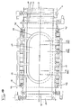
eine seitliche Schnittansicht einer modulartigen Zwischenplatte zur Vergrößerung der Anzahl der Schlammkammern,
eine Schnittansicht längs der Linie XV-XV von Fig. 12,
eine seitliche Schnittansicht einer praktischen Ausführungsform wie sie zur Durchführung des Verfahrens gemäß Fig. 2 bis 4 verwendet werden kann,
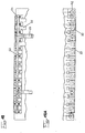
eine horizontale Schnittansicht der Vorrichtung gemäß Fig. 16,
Schnittansichten von Fig. 16 in der Ebene der Sperrklinken bzw. der Hubzylinder, wobei lediglich diese Details dargestellt sind,
eine Schnittansicht der Figuren 16 bzw. 17 längs der Linien XIX-XIX, wobei die Schlammkammern geöffnet dargestellt sind,
die Fig. 19 entsprechenden Stellungen der Hubzylinder bzw. der Sperrklinken, der Anschläge und des hydraulischen Betts,
eine Schnittansicht längs der Linien XXII-XXII von Fig. 16 bzw. 17, wobei die Schlammkammer verschlossen und verriegelt veranschaulicht ist,
Darstellungen entsprechend der Figuren 20 und 21, jedoch entsprechend dem Betriebszustand gemäß Fig. 22,
eine Schnittansicht längs der Linie XXV-XXV von Fig. 16 bzw. 17, wobei der Zustand der Erzeugung des zusätzlichen mechanischen Entwässerungsdrucks dargestellt ist,
Darstellungen entsprechend den Figuren 20 und 21 bzw. 23 und 24, jedoch in dem Betriebszustand gemäß Fig. 25,
eine Figur 12 entsprechende Darstellung einer weiteren sehr einfach aufgebauten Form der Schlammkammer,
eine Schnittansicht der Schlammkammer längs der Linie XXIX - XXIX von Figur 28,
eine Schnittansicht der erfindungsgemäß bei der Ausführungsform gemäß Figuren 16 und 17 verwendeten Dichtung in vier verschiedenen Betriebszuständen a bis d, und
eine Schnittansicht der erfindungsgemäß bei Ausführungsformen verwendeten Dichtung, welche mehr als eine Filterfläche in der Schlammkammer aufweist, in drei verschiedenen Betriebszuständen a bis c.
- 1
- Vorrichtung
- 2
- Vorentwässerungsstufe
- 3
- Zwischenbehälter
- 4
- Filterpresse
- 5
- Ausgleichsbehälter
- 6
- Kontinuierliche Schlammzufuhr
- 7
- Filterkorb
- 8
- Filtratauslaß
- 9
- Schlamm
- 10
- Schlammauslaßleitung
- 10a
- Schlammauslaß von 5
- 11
- Schlammeinlaß von 3
- 12
- Sperr- und Steuerventil
- 13
- Zylindergehäuse
- 14
- Kolben
- 15
- Antrieb von 14
- 16
- Hydraulikkolben
- 17
- Schlammauslaß v. 3
- 18
- Leitung
- 19
- Schlammeinlaß von 20
- 20
- Schlammkammer von 4
- 21
- Sperr- und Steuerventil
- 22
- Obere Druckplatte
- 23
- Untere Druckplatte
- 24
- Obere Filterfläche
- 25
- Untere Filterfläche
- 26
- Oberes Filterband
- 27
- Unteres Filterband
- 28
- Dichtung
- 29
- Oberer Schlammspiegel in 2
- 30
- Unterer Schlammspiegel in 2
- 31
- Lagerplatten
- 32
- Hydraulisches Bett
- 33
- Hochdruckerzeuger
- 34
- Antrieb von 35, 38
- 35
- Abstreifer
- 35a
- Stange
- 36
- E-Motor
- 37
- Stirnradgetriebe
- 38
- Wascheinrichtung
- 38a
- Waschdüse
- 38b
- Bürste
- 39
- Pfeile
- 40
- Mischer
- 40a
- Misch- und Förderschnecke
- 40b
- Dosiereinrichtung
- 41
- Motor
- 42
- Hubzylinder
- 43
- Wickelantrieb
- 44
- Wickelantrieb
- 45
- Austragsende
- 46
- Umlenkwalze
- 47
- Abstreifer
- 48
- Antrieb v. 49
- 49
- Waschdüse
- 50
- Wickelantrieb
- 51
- Wickelantrieb
- 52
- Umlenkwalze
- 53
- Abstreifer
- 54
- Sperrklinkenvorrichtung
- 55
- Sperrklinken
- 56
- Achsen
- 57
- Pneumatikzylinder
- 58
- Hebelantrieb
- 59
- Anschläge
- 60
- Hilfsrahmen
- 61
- Schubstange
- 62
- Mitnehmer
- 63
- Zwischenplatte
- 64
- Trägerplatte
- 65
- Oberes Filterband
- 66
- Unteres Filterband
- 67
- Wickelantrieb
- 68
- Wickelantrieb
- 69
- Wickelantrieb
- 70
- Wickelantrieb
- 71
- Mitnehmer von 63
- 72
- Mitnehmer von 63
- 73
- Oberteil von 59
- 74
- Filterkuchen
- 75
- Kanäle in 31
- 80
- Elastischer Körper 80
- 81
- Rahmen
- 82
- Bolzen
- 83
- Dichtlippe
- 84
- Dichtlippe
- 85
- Knickstelle
- 86
- Knickstelle
- 87
- Befestigungsvorsprung
- 88
- Ende
- 89
- Ende
- 90
- Abschnitt
- 103
- Schmiermittelbehälter
- 104
- Leitung
- 105
- Einlaß
- 106
- Ventil
- 116
- Kolbenstange
- 117
- Zylinder
Claims (19)
- Verfahren zum Entwässern von Schlamm und ähnlichen Substanzen, bei dem der Schlamm unter Druck in eine mindestens eine Filterfläche aufweisende, geschlossene Schlammkammer eingespeist, und in der Schlammkammer ein die Entwässerung herbeiführender hydrostatischer Druck aufgebaut wird, wobei nach erfolgter Entwässerung zum Abfördern des hergestellten Filterkuchens die Schlammkammer geöffnet und die Filterflächen mit dem Filterkuchen aus der Schlammkammer herausbewegt werden, dadurch gekennzeichnet, daß der Schlamm in mindestens einen mit der Schlammkammer in Verbindung stehenden Zwischenbehälter eingebracht wird, daß die Zwischenbehälter eine Schlammenge aufnehmen, die etwa dem Zweifachen des Volumens der Schlammkammer entspricht, daß danach die Schlammzufuhr zum Zwischenbehälter getrennt wird, daß anschließend die Schlammkammer durch positive Verdrängung eines Schlammvolumens aus dem Zwischenbehälter gefüllt wird, daß nach dem Füllen der Schlammkammer der hydrostatische Druck durch positive Verdrängung des das Volumen der Schlammkammer übersteigenden Teils der Füllung des Zwischenbehälters erzeugt wird, und daß hierbei je nach spezifischem Entwässerungsverhalten des Schlamms ein hydrostatischer Druck von etwa 5 bis 10 bar erzeugt wird.
- Verfahren nach Anspruch 1, dadurch gekennzeichnet, daß die Schlammzufuhr zu dem Zwischenbehälter über einen Ausgleichsbehälter erfolgt, welcher kontinuierlich mit Schlamm befüllt wird, daß in dem Ausgleichsbehälter eine Vorentwässerung des Schlamms durchgeführt wird, und daß der Schlamm in die Schlammkammer an mehreren Punkten gleichzeitig aus einer der Anzahl dieser Punkte entsprechenden Anzahl von Zwischenbehältern eingeleitet wird.
- Verfahren nach der Anspruch 1 oder 2, dadurch gekennzeichnet, daß nach Erreichen eines festlegbaren hydrostatischen Drucks in der Schlammkammer diese von dem Zwischenbehälter getrennt wird und daß danach das Volumen der Schlammkammer verkleinert wird und ein mechanischer Entwässerungsdruck erzeugt wird, welcher größer ist als der zuvor erreichte hydrostatische Druck.
- Vorrichtung zur Durchführung des Verfahrens nach einem der vorstehenden Ansprüche mit mindestens einer allseitig geschlossenen Schlammkammer, welche Filterflächen und einen Schlammeinlaß aufweist, der mit einer einen hydrostatischen Filtrationsdruck erzeugenden Einrichtung verbunden ist, wobei die Filterflächen zwischen relativ zueinander beweglichen Druckplatten angeordnet sind, und die Filterflächen zum Austragen des Filterkuchens nach Öffnen der Druckplatten bezüglich der Schlammkammer verschiebbar ausgebildet sind, dadurch gekennzeichnet, daß die Einrichtung zur Erzeugung des hydrostatischen Filtrationsdrucks als ein oder mehrere Zwischenbehälter (3) ausgebildet ist, daß der Zwischenbehälter (3) als Kolbenzylindereinheit (13, 14) mit einem Zylindergehäuse (13) und einem darin verschiebbaren Kolben 14) und einem Antrieb (15) für den Kolben (14) ausgebildet ist, wobei jede Kolbenzylindereinheit (13, 14) einen Schlammeinlaß (11) und einen mit der Schlammkammer (20) in Verbindung stehenden Schlammauslaß (17) aufweist, daß am Schlammeinlaß (11) und an Schlammauslaß (17) alternierend betätigbare Sperr- und Steuerventile (12, 21) vorgesehen sind, und daß das Volumen des oder der Zwischenbehälter (3) etwa dem zweifachen Volumen der Schlammkammer (20) entspricht.
- Vorrichtung nach Anspruch 4, dadurch gekennzeichnet, daß die Schlammkammer (20) mehrere Schlammeinlässe (19) aufweist, daß eine entsprechende Anzahl von Zwischenbehältern (3) vorgesehen ist, bei denen jeder Schlammauslaß (17) durch eine separate Verbindungsleitung (18, 18') mit einem der Schlammeinlässe (19) der Schlammkammer (20) verbunden ist, und daß die Sperr- und Steuerventile (12, 21) als Kugelhähne ausgebildet sind.
- Vorrichtung nach Anspruch 4 oder 5, dadurch gekennzeichnet, daß die Filterflächen (24, 25) durch geradlinig hin und her verschiebbare Filterbänder (26, 27, 65, 66) gebildet sind.
- Vorrichtung nach einem der Ansprüche 4 bis 6, dadurch gekennzeichnet, daß die Schlammkammer (20) durch eine obere und eine untere Filterfläche (24, 25) gebildet ist, zwischen denen eine die Schlammkammer (20) umgebende flexible Dichtung (28) angeordnet ist, daß die Dichtung (28) an einem Hilfsrahmen (60) befestigt ist, daß der Hilfsrahmen (60) durch Mitnehmer (62) beweglich an der oberen Druckplatte (22) aufgehängt ist, und daß die Schlammkammer (20) einen ovalen Umriß aufweist.
- Vorrichtung nach einem der Ansprüche 4 bis 7, dadurch gekennzeichnet, daß außerhalb der Schlammkammer (20) jede Filterfläche (24, 25) auf einer Lagerplatte (31) abgestützt ist, welche mit zur Filterfläche (24, 25) offenen Kanälen (75) versehen ist, daß die Schlammkammer (20) mit den Filterflächen (24, 25) geneigt in Längsrichtung angeordnet ist, daß die Neigung einem Gefälle der Filterflächen (24, 25) von etwa 10° entspricht, und daß die Kanäle (75) parallel zur Hauptachse der Schlammkammer (20) in Längsrichtung geradlinig ausgebildet sind.
- Vorrichtung nach einem der Ansprüche 4 bis 8, dadurch gekennzeichnet, daß die untere Druckplatte (23) auf Hochdruckerzeugern (33) abgestützt ist, mittels derer das Volumen der Schlammkammer (20) nach Erreichen des hydrostatischen Entwässerungsdrucks zur Erzeugung eines zusätzlichen mechanischen Entwässerungsdrucks verkleinerbar ist.
- Vorrichtung nach Anspruch 9, dadurch gekennzeichnet, daß die untere Druckplatte (23) als hydraulisches Bett (32) ausgebildet ist, indem nebeneinander eine Anzahl von Hochdruckerzeugern (33) über die Länge und/oder Breite der unteren Druckplatte (23) verteilt angeordnet sind, und daß die Hochdruckerzeuger in mehreren parallelen Reihen innerhalb des ovalen Umfangs der Schlammkammer (20) angeordnet sind, wobei die Hochdruckerzeuger (33) benachbarter Reihen gegeneinander versetzt sind.
- Vorrichtung nach Anspruch 9, dadurch gekennzeichnet, daß die Hochdruckerzeuger (33) seitlich außerhalb des Bereichs der Schlammkammer (20) angeordnet sind.
- Vorrichtung nach einem der Ansprüche 9 bis 11, dadurch gekennzeichnet, daß die Hochdruckerzeuger (33) als hydraulische Einfachzylinder ausgebildet sind.
- Vorrichtung nach einem der Ansprüche 4 bis 12, dadurch gekennzeichnet, daß die geschlossene Stellung der Schlammkammer (20) mechanisch verriegelbar ist, daß zur Verriegelung eine auf die obere Druckplatte (22) wirkende Sperrklinkenvorrichtung (54) vorgesehen ist.
- Vorrichtung nach einem der Ansprüche 4 bis 13, dadurch gekennzeichnet, daß mehrere Schlammkammern (20) übereinander angeordnet sind, und daß zur Herstellung jeweils einer weiteren Schlammkammer (20) zwischen der oberen und der unteren Druckplatte (22, 23) eine Zwischenplatte (63) vorgesehen ist, welche auf ihrer Ober- und Unterseite eine Lagerplatte (31) und je ein Filterband (65, 66) aufweist, wobei ferner auf der Unterseite ein Hilfsrahmen (60) mit Dichtung (28) aufgehängt ist.
- Vorrichtung nach einem der Ansprüche 4 bis 14, dadurch gekennzeichnet, daß vor der oder den Kolbenzylindereinheiten (13, 14) eine Vorentwässerungseinrichtung (2) vorgesehen ist, deren Schlammauslaß (10) mit dem Schlammeinlaß (11) der Kolbenzylindereinheiten (13, 14) verbunden ist, daß die Vorentwässerungseinrichtung (2) als Ausgleichsbehälter (5) ausgebildet ist, deren Einlaß an eine kontinuierliche Schlammzufuhr (6) angeschlossen ist, und daß die Vorentwässerungseinrichtung (2) ein oder mehrere in den Schlamm des Ausgleichsbehälters (5) eingetauchte Filterkörbe (7) aufweist, welche mit einem Filtratauslaß (8) versehen sind.
- Vorrichtung nach Anspruch 15, dadurch gekennzeichnet, daß der Filterkorb (7) ortsfest angeordnet ist, und daß ein oder mehrere über die Höhe des Filterkorbs (7) reichende Bürsten (38b) vorgesehen sind, welche auf der Filtratseite des Filterkorbs (7) umlaufen.
- Vorrichtung nach einem der Ansprüche 4 bis 16, dadurch gekennzeichnet, daß zwischen den Druckplatten (22, 23) und/oder Zwischenplatten (63) die Höhe der Schlammkammer (20) festlegende Anschläge (59) vorgesehen sind, und daß die Anschläge (59) entsprechend der Volumenverkleinerung der Schlammkammer (20) zusammendrückbar oder federnd ausgebildet sind.
- Vorrichtung nach einem der Ansprüche 4 bis 17, dadurch gekennzeichnet, daß die Dichtung (28) aus einem einstückigen, den Umfang der Druckkammer (20) umgebenden elastischen Körper (80) aus Gummi oder dergleichen besteht, daß der Körper (80) im Querschnitt die Form eines liegenden V aufweist, dessen Spitze von der Druckkammer weg nach außen gerichtet ist, daß die freien Enden (81, 82) des V je eine Dichtlippe (83, 84) bilden, und daß im horizontalen und vertikalen Abstand zu den Dichtlippen (83, 84) auf der Innenseite des V zwei einander gegenüberliegende Knickstellen (85, 86) vorgesehen sind, an welchen sich der zwischen den Schenkeln eingeschlossene Winkel vergrößert.
- Vorrichtung nach Anspruch 18, dadurch gekennzeichnet, daß der untere Schenkel des V parallel zum Boden der Druckkammer (20) verläuft, daß die Knickstellen (85, 86) asymmetrisch ausgebildet sind, indem die Winkelvergrößerung an der unteren Knickstelle (86) ein Vielfaches der Winkelvergrösserung an der oberen Knickstelle (85) beträgt, daß der symmetrische Teil des V vor den Knickstellen (85, 86) als Einschnitt in einem Bereich der Dichtung (28) mit rechteckigem Querschnitt ausgebildet ist, und daß die Spitze des V außen mit einem umlaufenden Einspann- oder Befestigungsvorsprung (87) verbunden ist.
Applications Claiming Priority (4)
| Application Number | Priority Date | Filing Date | Title |
|---|---|---|---|
| DE4442623 | 1994-12-01 | ||
| DE4442623 | 1994-12-01 | ||
| DE19539484A DE19539484C2 (de) | 1994-12-01 | 1995-10-24 | Verfahren und Vorrichtung zum Entwässern von Schlämmen und ähnlichen Substanzen |
| DE19539484 | 1995-10-24 |
Publications (3)
| Publication Number | Publication Date |
|---|---|
| EP0714687A2 EP0714687A2 (de) | 1996-06-05 |
| EP0714687A3 EP0714687A3 (de) | 1996-08-21 |
| EP0714687B1 true EP0714687B1 (de) | 1999-04-07 |
Family
ID=25942438
Family Applications (1)
| Application Number | Title | Priority Date | Filing Date |
|---|---|---|---|
| EP95118363A Expired - Lifetime EP0714687B1 (de) | 1994-12-01 | 1995-11-22 | Verfahren und Vorrichtung zum Entwässern von Schlämmen und ähnlichen Substanzen |
Country Status (5)
| Country | Link |
|---|---|
| US (1) | US5863429A (de) |
| EP (1) | EP0714687B1 (de) |
| JP (1) | JP3693729B2 (de) |
| AT (1) | ATE178499T1 (de) |
| FI (1) | FI112647B (de) |
Families Citing this family (18)
| Publication number | Priority date | Publication date | Assignee | Title |
|---|---|---|---|---|
| US5961827A (en) * | 1996-08-28 | 1999-10-05 | Baehr; Albert | Apparatus for dewatering of sludge and similar substances |
| DE29614898U1 (de) * | 1996-08-28 | 1996-12-19 | Bähr, Albert, Dipl.-Ing., 66564 Ottweiler | Vorrichtung zum Entwässern von Schlamm und ähnlichen Substanzen |
| US6256902B1 (en) * | 1998-11-03 | 2001-07-10 | John R. Flaherty | Apparatus and method for desiccating and deagglomerating wet, particulate materials |
| DE19900187C1 (de) * | 1999-01-06 | 2000-06-15 | Stockhausen Chem Fab Gmbh | Verfahren zur Entwässerung von Klärschlämmen mit Plattenfiltern (Filterpressen) |
| US7383766B2 (en) * | 2001-08-29 | 2008-06-10 | Mte Research Pty Ltd | Coal dewatering system and method |
| EP1559469B1 (de) * | 2004-01-30 | 2011-10-12 | P.M.P.O. S.R.L. | Anlage und Verfahren zur Behandlung eines Kühlfluids in mechanischen Bearbeitungsanlagen |
| US7208087B2 (en) * | 2005-02-15 | 2007-04-24 | Bio-Rad Laboratories, Inc. | Dual-chamber chromatographic cartridge |
| DE102008047427A1 (de) * | 2008-09-15 | 2010-04-15 | Bähr, Albert, Dipl.-Ing. | Verfahren und Vorrichtung zur Fest-Flüssig-Trennung von Stoffgemischen und Suspensionen |
| US20110084029A1 (en) * | 2009-10-08 | 2011-04-14 | Dominick O' Reilly | Waste treatment system |
| US20110089097A1 (en) * | 2009-10-19 | 2011-04-21 | O'reilly Dominick | Attachment and system for dewatering material |
| US20110094395A1 (en) * | 2009-10-26 | 2011-04-28 | O'reilly Dominick | Method and attachment for dewatering logs |
| DE202012008238U1 (de) * | 2012-08-29 | 2012-09-26 | Albert Bähr | Vorrichtung zur Fest-Flüssig-Trennung von Stoffgemischen und Suspensionen |
| CN103432790B (zh) * | 2013-09-02 | 2015-08-05 | 无锡锦和科技有限公司 | 压滤机的滑移式进料机构 |
| CN106746459A (zh) * | 2016-12-27 | 2017-05-31 | 重庆亚协环保工程有限公司 | 浮选物压干设备 |
| US20180280840A1 (en) * | 2017-03-29 | 2018-10-04 | Larry Baxter | Method and Device for Separating Solids and Liquids using a Modified Pump |
| SE544566C2 (en) * | 2020-01-31 | 2022-07-19 | Hydria Water Ab | A separation device and method to separate contaminants from contaminated water |
| KR102795458B1 (ko) * | 2020-09-25 | 2025-04-11 | 주식회사 엘지화학 | 압축식 탈수기 |
| JP2024043122A (ja) * | 2022-09-16 | 2024-03-29 | キオクシア株式会社 | 端材回収装置 |
Family Cites Families (10)
| Publication number | Priority date | Publication date | Assignee | Title |
|---|---|---|---|---|
| US3796316A (en) * | 1972-07-07 | 1974-03-12 | A Matz | Water filtering apparatus |
| US4387633A (en) * | 1981-02-06 | 1983-06-14 | James Ballantyne | Sludge processing system |
| ZA822150B (en) * | 1981-04-10 | 1983-11-30 | Prestige Group Plc | Pressure cookers |
| JPS61126009A (ja) * | 1984-11-21 | 1986-06-13 | Yasuo Arai | 化粧料の充填固化方法および充填固化装置 |
| DE3734974A1 (de) * | 1986-10-21 | 1989-04-20 | Baehr Albert | Vorrichtung zum entwaessern von schlamm und aehnlichen substanzen |
| DE3914661C2 (de) * | 1989-05-03 | 1998-04-23 | Baehr Albert | Vorrichtung zur Fest-Flüssig-Trennung |
| NO901889L (no) * | 1989-05-10 | 1990-11-12 | Albert Baehr | Fremgangsmaate ved og kammerfilterpresse for avvanning av slam og lignende substanser. |
| DE3923298C1 (de) * | 1989-07-14 | 1991-01-24 | Friedrich 7517 Waldbronn De Banzhaf | |
| US5236583A (en) * | 1992-05-20 | 1993-08-17 | Wang Yiu Te | High-pressure/vacuum operated apparatus for sewage and mud disposal |
| DE4223022A1 (de) * | 1992-07-14 | 1994-01-20 | Baehr Albert | Vorrichtung zum Entwässern von Schlamm und ähnlichen Substanzen |
-
1995
- 1995-11-22 AT AT95118363T patent/ATE178499T1/de not_active IP Right Cessation
- 1995-11-22 EP EP95118363A patent/EP0714687B1/de not_active Expired - Lifetime
- 1995-11-28 US US08/563,426 patent/US5863429A/en not_active Expired - Fee Related
- 1995-11-30 FI FI955771A patent/FI112647B/fi active
- 1995-12-01 JP JP33565095A patent/JP3693729B2/ja not_active Expired - Fee Related
Also Published As
| Publication number | Publication date |
|---|---|
| JP3693729B2 (ja) | 2005-09-07 |
| FI955771A0 (fi) | 1995-11-30 |
| ATE178499T1 (de) | 1999-04-15 |
| EP0714687A3 (de) | 1996-08-21 |
| EP0714687A2 (de) | 1996-06-05 |
| JPH08224600A (ja) | 1996-09-03 |
| FI955771A7 (fi) | 1996-06-02 |
| US5863429A (en) | 1999-01-26 |
| FI112647B (fi) | 2003-12-31 |
Similar Documents
| Publication | Publication Date | Title |
|---|---|---|
| EP0714687B1 (de) | Verfahren und Vorrichtung zum Entwässern von Schlämmen und ähnlichen Substanzen | |
| EP0827767B1 (de) | Vorrichtung zum Entwässern von Schlamm und ähnlichen Substanzen | |
| DE2844697C2 (de) | Filterpresse zum Entwässern von Schlamm und ähnlichen Substanzen | |
| EP2165746B1 (de) | Verfahren und Vorrichtung zur Fest-Flüssig-Trennung von Stoffgemischen und Suspensionen | |
| EP0397082B1 (de) | Verfahren und Vorrichtung zum Entwässern von Schlämmen und ähnlichen Substanzen | |
| EP0654294A2 (de) | Verfahren und Vorrichtung zum Ausfiltrieren und Rückspülen von Feststoff-Partikeln aus Flüssigkeiten | |
| DE2725645A1 (de) | Verfahren und vorrichtung zum kontinuierlichen filtern mittels eines endlosfilterbandes | |
| EP0264899B1 (de) | Vorrichtung zum Entwässern von Schlamm und ähnlichen Substanzen | |
| DE2533719A1 (de) | Filterpresse | |
| EP0178389B1 (de) | Kammerfilterpresse | |
| DD252766A5 (de) | Filterpresse | |
| EP0245490B1 (de) | Filterpresse für die flussigkeitsabtrennung aus schlämmen bis auf einen hohen feststoff-gehalt | |
| DE10207451A1 (de) | Vorrichtung und Verfahren zur Entwässerung von Schlämmen | |
| DE19539484C2 (de) | Verfahren und Vorrichtung zum Entwässern von Schlämmen und ähnlichen Substanzen | |
| DE2731043A1 (de) | Doppelt wirkende filterpresse | |
| DD294237A5 (de) | Verfahren und kammerfilterpresse zum entwaessern von schlaemmen und aehnlichen substanzen | |
| EP0982058B1 (de) | Vorrichtung zum Entwässern von Schlamm und ähnlichen Substanzen | |
| DE19632964C1 (de) | Filterpresse | |
| DE4223022A1 (de) | Vorrichtung zum Entwässern von Schlamm und ähnlichen Substanzen | |
| AT396923B (de) | Verfahren und trenneinrichtung zum auftrennen bzw. entwässern von flüssigkeit-feststoff-gemischen | |
| DE4020405A1 (de) | Verfahren zur druckentwaesserung von waessrigen schlaemmen | |
| DE2114764A1 (de) | Filterpresse | |
| DE4321383C1 (de) | Verfahren zum Entleerungsbetrieb einer Preßvorrichtung für die Entwässerung von Schlamm | |
| AT225720B (de) | Vorrichtung und Verfahren zum Auspressen von Flüssigkeit aus flüssigkeitshaltigem, feinkörnigem Gut, wie Kohlenschlamm u. dgl. | |
| DE1924471A1 (de) | Filterband |
Legal Events
| Date | Code | Title | Description |
|---|---|---|---|
| PUAI | Public reference made under article 153(3) epc to a published international application that has entered the european phase |
Free format text: ORIGINAL CODE: 0009012 |
|
| AK | Designated contracting states |
Kind code of ref document: A2 Designated state(s): AT CH DE FR GB IT LI SE |
|
| PUAL | Search report despatched |
Free format text: ORIGINAL CODE: 0009013 |
|
| AK | Designated contracting states |
Kind code of ref document: A3 Designated state(s): AT CH DE FR GB IT LI SE |
|
| 17P | Request for examination filed |
Effective date: 19970411 |
|
| 17Q | First examination report despatched |
Effective date: 19970915 |
|
| GRAG | Despatch of communication of intention to grant |
Free format text: ORIGINAL CODE: EPIDOS AGRA |
|
| GRAG | Despatch of communication of intention to grant |
Free format text: ORIGINAL CODE: EPIDOS AGRA |
|
| GRAH | Despatch of communication of intention to grant a patent |
Free format text: ORIGINAL CODE: EPIDOS IGRA |
|
| GRAH | Despatch of communication of intention to grant a patent |
Free format text: ORIGINAL CODE: EPIDOS IGRA |
|
| GRAA | (expected) grant |
Free format text: ORIGINAL CODE: 0009210 |
|
| AK | Designated contracting states |
Kind code of ref document: B1 Designated state(s): AT CH DE FR GB IT LI SE |
|
| PG25 | Lapsed in a contracting state [announced via postgrant information from national office to epo] |
Ref country code: SE Free format text: THE PATENT HAS BEEN ANNULLED BY A DECISION OF A NATIONAL AUTHORITY Effective date: 19990407 |
|
| REF | Corresponds to: |
Ref document number: 178499 Country of ref document: AT Date of ref document: 19990415 Kind code of ref document: T |
|
| REG | Reference to a national code |
Ref country code: CH Ref legal event code: NV Representative=s name: ISLER & PEDRAZZINI AG Ref country code: CH Ref legal event code: EP |
|
| GBT | Gb: translation of ep patent filed (gb section 77(6)(a)/1977) |
Effective date: 19990413 |
|
| REF | Corresponds to: |
Ref document number: 59505582 Country of ref document: DE Date of ref document: 19990512 |
|
| ET | Fr: translation filed | ||
| PLBE | No opposition filed within time limit |
Free format text: ORIGINAL CODE: 0009261 |
|
| STAA | Information on the status of an ep patent application or granted ep patent |
Free format text: STATUS: NO OPPOSITION FILED WITHIN TIME LIMIT |
|
| 26N | No opposition filed | ||
| REG | Reference to a national code |
Ref country code: GB Ref legal event code: IF02 |
|
| REG | Reference to a national code |
Ref country code: CH Ref legal event code: PCAR Free format text: ISLER & PEDRAZZINI AG;POSTFACH 1772;8027 ZUERICH (CH) |
|
| PGFP | Annual fee paid to national office [announced via postgrant information from national office to epo] |
Ref country code: DE Payment date: 20081128 Year of fee payment: 14 Ref country code: CH Payment date: 20081128 Year of fee payment: 14 |
|
| PGFP | Annual fee paid to national office [announced via postgrant information from national office to epo] |
Ref country code: AT Payment date: 20081128 Year of fee payment: 14 |
|
| PGFP | Annual fee paid to national office [announced via postgrant information from national office to epo] |
Ref country code: IT Payment date: 20081128 Year of fee payment: 14 |
|
| PGFP | Annual fee paid to national office [announced via postgrant information from national office to epo] |
Ref country code: FR Payment date: 20080930 Year of fee payment: 14 |
|
| PGFP | Annual fee paid to national office [announced via postgrant information from national office to epo] |
Ref country code: GB Payment date: 20081113 Year of fee payment: 14 |
|
| REG | Reference to a national code |
Ref country code: CH Ref legal event code: PL |
|
| GBPC | Gb: european patent ceased through non-payment of renewal fee |
Effective date: 20091122 |
|
| REG | Reference to a national code |
Ref country code: FR Ref legal event code: ST Effective date: 20100730 |
|
| PG25 | Lapsed in a contracting state [announced via postgrant information from national office to epo] |
Ref country code: AT Free format text: LAPSE BECAUSE OF NON-PAYMENT OF DUE FEES Effective date: 20091122 |
|
| PG25 | Lapsed in a contracting state [announced via postgrant information from national office to epo] |
Ref country code: LI Free format text: LAPSE BECAUSE OF NON-PAYMENT OF DUE FEES Effective date: 20091130 Ref country code: FR Free format text: LAPSE BECAUSE OF NON-PAYMENT OF DUE FEES Effective date: 20091130 Ref country code: CH Free format text: LAPSE BECAUSE OF NON-PAYMENT OF DUE FEES Effective date: 20091130 |
|
| PG25 | Lapsed in a contracting state [announced via postgrant information from national office to epo] |
Ref country code: DE Free format text: LAPSE BECAUSE OF NON-PAYMENT OF DUE FEES Effective date: 20100601 |
|
| PG25 | Lapsed in a contracting state [announced via postgrant information from national office to epo] |
Ref country code: GB Free format text: LAPSE BECAUSE OF NON-PAYMENT OF DUE FEES Effective date: 20091122 |
|
| PG25 | Lapsed in a contracting state [announced via postgrant information from national office to epo] |
Ref country code: IT Free format text: LAPSE BECAUSE OF NON-PAYMENT OF DUE FEES Effective date: 20091122 |