EP0714746B1 - Dispositif de moulage par injection pour disques avec moyens de guidage de l'ouverture de moule - Google Patents
Dispositif de moulage par injection pour disques avec moyens de guidage de l'ouverture de moule Download PDFInfo
- Publication number
- EP0714746B1 EP0714746B1 EP19950109880 EP95109880A EP0714746B1 EP 0714746 B1 EP0714746 B1 EP 0714746B1 EP 19950109880 EP19950109880 EP 19950109880 EP 95109880 A EP95109880 A EP 95109880A EP 0714746 B1 EP0714746 B1 EP 0714746B1
- Authority
- EP
- European Patent Office
- Prior art keywords
- guide
- mold
- disc
- guide ring
- outer diameter
- Prior art date
- Legal status (The legal status is an assumption and is not a legal conclusion. Google has not performed a legal analysis and makes no representation as to the accuracy of the status listed.)
- Expired - Lifetime
Links
- 238000002347 injection Methods 0.000 title claims description 28
- 239000007924 injection Substances 0.000 title claims description 28
- 239000000463 material Substances 0.000 claims description 19
- 238000005452 bending Methods 0.000 claims description 3
- 238000006073 displacement reaction Methods 0.000 description 9
- 239000011347 resin Substances 0.000 description 8
- 229920005989 resin Polymers 0.000 description 8
- 238000001746 injection moulding Methods 0.000 description 7
- 230000003287 optical effect Effects 0.000 description 6
- 230000007246 mechanism Effects 0.000 description 5
- 238000010586 diagram Methods 0.000 description 4
- 238000000465 moulding Methods 0.000 description 4
- 239000000314 lubricant Substances 0.000 description 3
- PXHVJJICTQNCMI-UHFFFAOYSA-N Nickel Chemical compound [Ni] PXHVJJICTQNCMI-UHFFFAOYSA-N 0.000 description 2
- 230000000712 assembly Effects 0.000 description 2
- 238000000429 assembly Methods 0.000 description 2
- 239000011248 coating agent Substances 0.000 description 2
- 238000000576 coating method Methods 0.000 description 2
- 238000000034 method Methods 0.000 description 2
- CWQXQMHSOZUFJS-UHFFFAOYSA-N molybdenum disulfide Chemical compound S=[Mo]=S CWQXQMHSOZUFJS-UHFFFAOYSA-N 0.000 description 2
- 229910052982 molybdenum disulfide Inorganic materials 0.000 description 2
- 230000002159 abnormal effect Effects 0.000 description 1
- 230000006866 deterioration Effects 0.000 description 1
- 238000010438 heat treatment Methods 0.000 description 1
- 239000012535 impurity Substances 0.000 description 1
- 229910000734 martensite Inorganic materials 0.000 description 1
- 238000005259 measurement Methods 0.000 description 1
- 238000012986 modification Methods 0.000 description 1
- 230000004048 modification Effects 0.000 description 1
- 229910052759 nickel Inorganic materials 0.000 description 1
- 229910001220 stainless steel Inorganic materials 0.000 description 1
- 239000000126 substance Substances 0.000 description 1
- 229910000601 superalloy Inorganic materials 0.000 description 1
- 238000004381 surface treatment Methods 0.000 description 1
Images


Classifications
-
- B—PERFORMING OPERATIONS; TRANSPORTING
- B29—WORKING OF PLASTICS; WORKING OF SUBSTANCES IN A PLASTIC STATE IN GENERAL
- B29C—SHAPING OR JOINING OF PLASTICS; SHAPING OF MATERIAL IN A PLASTIC STATE, NOT OTHERWISE PROVIDED FOR; AFTER-TREATMENT OF THE SHAPED PRODUCTS, e.g. REPAIRING
- B29C45/00—Injection moulding, i.e. forcing the required volume of moulding material through a nozzle into a closed mould; Apparatus therefor
- B29C45/17—Component parts, details or accessories; Auxiliary operations
- B29C45/26—Moulds
- B29C45/263—Moulds with mould wall parts provided with fine grooves or impressions, e.g. for record discs
Definitions
- the present invention relates to a disc injection mold apparatus having mold opening guide means for preventing the axis displacement between the stationary and movable disc cavity molds caused when mold opening.
- the present invention relates to a disc injection mold apparatus having mold opening guide means capable of preventing damage of the signal bits transferred to the surface of a molded optical disc due to the axis displacement between the stationary and movable disc cavity molds caused when the mold is opened following the completion of the injection molding.
- a disc injection mold apparatus which comprises stationary and movable mold bases, cylindrical disc cavity molds provided at the center of each of the bases, and a pair of cylindrical guide rings provided concentrically at the outer peripheries of each of the disc cavity molds as alignment guide means, circumference surface joint sections of each tip ends thereof being male and female tapered fitting surfaces has been used.
- Fig. 6 is a sectional view of the conventional disc injection mold apparatus when mold clamping
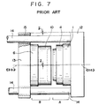
- Fig. 7 is a diagram of the conventional apparatus in a state of mold opening for explaining problems thereof.
- side A is a stationary mold assembly and side B is a movable mold assembly.
- a disc cavity mold 2 is fixed to the stationary mold base 1 of the stationary mold assembly A, and an injection nozzle 3 for injecting a molten resin material is provided at the center thereof.
- a cylindrical stationary guide ring 4 is integrally fixed to the outer periphery of the stationary mold base 1, and is provided with a male tapered surface 5 at the left end surface thereof with an angle of inclination of 3 to 5 degrees. To a center hole of the stationary mold base 1, resin is supplied from a molding nozzle 28 when injection molding.
- a movable disc cavity mold 7 is fixed to the movable mold base 6 of the movable mold assembly B, and a cavity 8 into which a molten resin material is charged is formed between the stationary disc cavity mold 2 and the movable disc cavity mold 7.
- a stamper plate 9 is made of a pure nickel, and fine signal bits are formed on the surface (right surface in Fig. 6) thereof. The stamper plate 9 is secured to the surface of the movable disc cavity mold 7 with a mounting member (not shown).
- a cylindrical movable guide ring 10 is integrally fixed to the outer periphery of the movable mold base 6 or the movable disc cavity mold 7.
- a female tapered surface 11 precisely fitting to the male tapered surface 5 of the stationary mold is formed on the right end surface of the cylindrical movable guide ring 10.
- the mold assemblies A and B as described above are mounted on a stationary platen 12 and a movable platen 13 of the injection mold machine, respectively.
- the molten resin material is charged into the cavity 8 formed between the cavity molds 2 and 7 at a high pressure and molded so as to transfer the fine signal bits of the stamper plate 9 to the resin molded article.
- the movable platen 13 is moved backwardly to perform mold opening, and the entire resin molded article is removed from the mold.
- the movable platen 13 is held by four guide rods 14 and driven by a pressure device such as a toggle mechanism and a hydraulic piston (not shown).
- a phenomenon occurs in which an axis of the movable mold assembly B coincided with an axis of the stationary mold assembly A by a tapered surface guide mechanism when mold clamping gradually moves downwardly as the mold opening process proceeds by the deflection value ⁇ according to the downward deflection value ⁇ of the guide rods 14 due to a gap formed between a bearing 15 of the movable platen 13 and the guide rods 14, and to weights of the movable platen 13 and the movable mold assembly B.
- the deflection value ⁇ of the injection molding machine having a mold clamping ability of 75 tons or more reaches 50 to 70 ⁇ m by actual measurement.
- the mold In case of high speed molding of the optical disc, the mold is opened in a state where inside of the resin molded article is partially molten state and the surface thereof is not completely solidified.
- the axis displacement between the stationary mold assembly A and the movable mold assembly B should be maintained in zero state until the mold opening distance reaches at least 200 ⁇ m. If not, inconvenience such as deformation or double transferring of the fine signal bits transferred to the resin molded article.
- the deflection value ⁇ may reach 17.5 ⁇ m in a state where the mold opening distance is 200 ⁇ m.
- each of the tapered surfaces are subjected to a hardening treatment, a molybdenum disulfide coating treatment and the like.
- a disc injection mold apparatus having mold opening guide means for opening mold sideways, comprising: stationary and movable mold bases; cylindrical disc cavity molds provided at the center of each of the bases; and a pair of cylindrical guide rings provided concentrically at the outer peripheries of each of the disc cavity molds as alignment guide means, axial hole joint sections of each tip ends thereof being male and female tapered fitting surfaces, wherein a plurality of parallel grooves each having a surface formed by a hard material are provided at the outer diameter surface of one of the guide ring and a plurality of guide blocks each having a surface formed by a hard material and fitting precisely to the parallel groove are formed at the tip end of the outer diameter surface of the other guide ring so that each of the cavity molds are maintained concentrically by a fitting of the guide blocks to the grooves at the time of mold opening.
- a disc injection mold apparatus wherein the plurality of parallel grooves are a pair of grooves provided at both sides of the outer diameter surface of one of the guide rings.
- a disc injection mold apparatus wherein three or more parallel grooves are provided at equal angles on the outer diameter surface of one of the guide rings.
- a disc injection mold apparatus wherein the guide blocks each having the upper and lower surfaces parallel to the parallel grooves provided at the right and left sides on the outer diameter surface of the one guide ring are made of a wear resistant material and secured to the end surface of the guide ring so as to protrude therefrom.
- a disc injection mold apparatus wherein a plate made of a wear resistant material such as cemented carbide is secured to either or both upper and lower surfaces of the parallel grooves provided at right and left sides of the outer diameter surface of other guide ring fitting to the upper and lower surfaces of the guide blocks of the parallel grooves.
- a material to be used for the guide grooves and the guide blocks is a cemented carbide having a rockwell hardness of HRA 83 to 89 and a transverse bending force of 200 kgf/mm 2 .
- Fig. 1 is a side view showing an embodiment of a stationary guide ring of a mold apparatus according to the present invention
- Fig. 2 is a front view partially in cross section of the above stationary guide ring.
- a male tapered surface 17 with an angle of inclination of 5 degrees is formed on the left end surface of the stationary guide ring 16.
- the angle of inclination is exaggerated for the purpose of easy understanding.
- a pair of precisely worked right and left parallel grooves 18 each having a width W 1 are provided in the outer diameter surface of the stationary guide ring 16, as shown in Fig. 1.
- Fig. 3 is a front view partially in cross section of an embodiment of a movable guide ring of the mold apparatus according to the present invention
- Fig. 4 is a side view of the above embodiment of the movable guide ring.
- a female tapered surface 20 with the same angle of inclination as that of the male tapered surface 17 of the stationary guide ring 16 is formed on the left end circumference section of a cylindrical movable guide ring 19.
- a pair of precisely worked right and left parallel grooves 21 each having a width W 1 are provided at positions corresponding to those of the stationary guide ring 16 in the outer diameter surface of the movable guide ring 19.
- Guide blocks 22 made of superalloy materials each having a width W 2 and a height H are secured to the parallel grooves 21 with check bolts 23, respectively.
- the stationary guide ring 16 and the movable guide ring 19 are secured with check bolts (not shown)to the stationary mold base and the movable mold base similar to those of shown in Fig. 6 or Fig. 7, respectively.
- the entire contacting surfaces of the upper surfaces of the precisely worked parallel grooves 18 of the stationary guide ring 16 with the upper and lower surfaces of the guide blocks 22 of the movable guide ring 19 are pressure sliding friction surfaces because a tapered surface fitting is not used therefor.
- any lubricant can not be used in the optical disc injection mold as described above. Therefore, selection of materials for each sections of the apparatus is an important factor to ensure durable stability of the disc injection mold.
- a cemented carbide having a rockwell hardness of HRA 83 to 89 and a transverse bending force of 200 kgf/mm 2 is used as a material for the guide blocks 22.
- Martensitic stainless steels such as SUS420, SUS440 and the like subjected to a heat treatment so as to be hardened are used as materials of the stationary guide ring 16 and movable guide ring 19, and the stationary guide ring 16 is subjected to wear resistant surface treatment such as molybdenum disulfide coating.
- the width W 1 of the precisely worked parallel groove 18 of the stationary guide ring 16 and the width W 2 of the guide block 22 of the movable guide ring 19 are precisely produced so that the fitting gap formed therebetween is within 3 ⁇ m at normal temperatures.
- a fitting length S 2 between the guide block 22 and the parallel groove 18 of the stationary guide ring 16 is set at least over 5 mm longer than the length S 1 of the tapered section so that the guide block 22 precedes the tapered guide surface by 5 mm to be fitted into the precisely worked parallel groove 18 of the stationary guide ring 16.
- Figs. 5(I) to 5(III) are schematic diagrams which show the operation of the guide mechanism of the disc injection mold apparatus having a mold opening means according to the present invention.
- Fig. 5(I) shows a state where the stationary guide ring 16 is joined to the movable guide ring 19 at a mold clamping position.
- a tapered guide surfaces 17, 20 and the guide block 22 are simultaneously fitted to and in contact with the parallel groove 18 of the stationary guide ring 16. Therefore, a center line «aa» of the stationary mold assembly A coincide with a center line «bb» of the movable mold assembly B.
- Fig. 5(II) shows a state where the mold is opened by very short distance S 1 with the tapered guide surfaces 17 and 20 are held by the guide block 22 so that the center line «aa» of the stationary mold assembly A coincides with the center line «bb» of the movable mold assembly B.
- Fig. 5(III) shows a state of a moment the mold opening distance exceeds S 2 , whereby the guide block 22 of the movable mold assembly B is separated from the parallel grooves 18 of the stationary guide ring 16.
- the center line «bb» of the movable mold assembly B rapidly moves downwardly by the above-mentioned deflection value ⁇ so as to be displaced with respect to the center line «aa» of the stationary mold assembly A.
- the center line «aa» of the stationary mold assembly A coincides with the center line «bb» of the movable mold assembly B so that the axis displacement therebetween can be maintained in zero state.
- the longitudinal and transverse axis displacement between the stationary and movable mold assemblies A and B can be simultaneously controlled.
- the guide mechanism capable of moving horizontally the stationary and movable molds is provided to prevent the longitudinal axis displacement between the stationary and movable molds caused when the mold is opened following the injection molding. Therefore, displacements of the fine signal bits transferred to the optical disc molded article and quality deterioration of the molded substance due to double transferring can be prevented.
- the guide block and guide groove have durable stability in point of wear resistance even in an environment where lubricants can not be used.
- the guide rings are equipped with all the guide mechanisms composed of the guide blocks and guide groove surfaces. Thus, the additional volume increase of the mold is not required, whereby a compact and lightweight mold can be designed.
- the disc injection mold apparatus having mold opening means according to the present invention can be provided by improving only guide ring sections of the conventional apparatus.
Landscapes
- Engineering & Computer Science (AREA)
- Manufacturing & Machinery (AREA)
- Mechanical Engineering (AREA)
- Moulds For Moulding Plastics Or The Like (AREA)
- Manufacturing Optical Record Carriers (AREA)
Claims (6)
- Appareil de moulage par injection de disques ayant des moyens de guidage d'ouverture de moule pour l'ouverture du moule latéralement, comprenant :des châssis fixe et mobile (1, 6),des matrices à cavité à disque cylindriques (2, 7) prévues au centre de chacun desdits châssis (1, 6), etune paire d'anneaux de guidage cylindriques (16, 19) prévus concentriquement aux périphéries extérieures de chacune desdites matrices à cavité à disque (2, 7) comme moyens de guidage d'alignement, des parties de joint de trou axial de chaque extrémité de ceux-ci étant des surfaces d'ajustement coniques mâle et femelle (17, 20),dans lequel plusieurs rainures parallèles (18) ayant chacune une surface formée d'une matière dure sont prévues à la surface de diamètre extérieur d'un desdits anneaux de guidage (16) et plusieurs blocs de guidage (22) ayant chacun une surface formée d'une matière dure et s'ajustant avec précision à ladite rainure parallèle (18) sont formés à l'extrémité de la surface de diamètre extérieur de l'autre anneau de guidage (19) de façon que chacune desdites matrices à cavité (2, 7) soit maintenue concentriquement par un ajustement desdits blocs de guidage (22) auxdites rainures (18) au moment de l'ouverture du moule.
- Appareil de moulage par injection de disques ayant des moyens de guidage d'ouverture de moule selon la revendication 1, dans lequel les rainures parallèles (18) sont une paire de rainures prévues sur les deux côtés de la surface de diamètre extérieur d'un desdits anneaux de guidage (16).
- Appareil de moulage par injection de disques ayant des moyens de guidage d'ouverture de moule selon la revendication 1, dans lequel trois ou plus de trois rainures parallèles (18) sont prévues à des angles égaux sur la surface de diamètre extérieur d'un desdits anneaux de guidage (19).
- Appareil de moulage par injection de disques ayant des moyens de guidage d'ouverture de moule selon l'une des revendications 1 à 3, dans lequel lesdits blocs de guidage (22) ayant chacun les surfaces supérieure et inférieure parallèles auxdites rainures parallèles (18) prévues sur les côtés droit et gauche sur la surface de diamètre extérieur d'un anneau de guidage (16) sont faits d'une matière résistant à l'usure et fixés à la surface d'extrémité dudit anneau de guidage (19) de façon à saillir de celui-ci.
- Appareil de moulage par injection de disques ayant des moyens de guidage d'ouverture de moule selon l'une des revendications 1 à 4, dans lequel une plaque faite d'une matière résistant à l'usure telle que carbure cémenté est fixée soit à une des surfaces supérieure et inférieure, soit aux deux, desdites rainures parallèles (18) prévues sur les côtés droit et gauche de la surface de diamètre extérieur de l'autre anneau de guidage (16) s'ajustant aux surfaces supérieure et inférieure desdits blocs de guidage (22) desdites rainures parallèles.
- Appareil de moulage par injection de disques ayant des moyens de guidage d'ouverture de moule selon l'une des revendications 1 à 5, dans lequel une matière utilisable pour lesdites rainures de guidage (18) et lesdits blocs de guidage (22) est un carbure cémenté ayant une dureté Rockwell HRA de 83 à 89 et une force de flexion transversale de 200 kgf/mm2.
Applications Claiming Priority (3)
| Application Number | Priority Date | Filing Date | Title |
|---|---|---|---|
| JP32175894A JP2974238B2 (ja) | 1994-11-30 | 1994-11-30 | 型開き案内手段をもつディスク射出成形金型装置 |
| JP32175894 | 1994-11-30 | ||
| JP321758/94 | 1994-11-30 |
Publications (3)
| Publication Number | Publication Date |
|---|---|
| EP0714746A2 EP0714746A2 (fr) | 1996-06-05 |
| EP0714746A3 EP0714746A3 (fr) | 1996-12-27 |
| EP0714746B1 true EP0714746B1 (fr) | 1999-08-18 |
Family
ID=18136122
Family Applications (1)
| Application Number | Title | Priority Date | Filing Date |
|---|---|---|---|
| EP19950109880 Expired - Lifetime EP0714746B1 (fr) | 1994-11-30 | 1995-06-24 | Dispositif de moulage par injection pour disques avec moyens de guidage de l'ouverture de moule |
Country Status (3)
| Country | Link |
|---|---|
| EP (1) | EP0714746B1 (fr) |
| JP (1) | JP2974238B2 (fr) |
| DE (1) | DE69511510T2 (fr) |
Families Citing this family (6)
| Publication number | Priority date | Publication date | Assignee | Title |
|---|---|---|---|---|
| JP3152601B2 (ja) * | 1995-11-17 | 2001-04-03 | 株式会社精工技研 | ディスク射出成形金型の固定側と可動側の円盤キャビティプレートの整列案内装置 |
| JPH1170529A (ja) * | 1997-08-29 | 1999-03-16 | Seiko Giken:Kk | ディスク成形用金型 |
| US7300271B2 (en) | 2005-12-01 | 2007-11-27 | Nokia Corporation | Injection mold insert block alignment system |
| CN103407031A (zh) * | 2013-08-22 | 2013-11-27 | 昆山振兴精密模具有限公司 | 一种模具导位器 |
| DE102015112527B4 (de) * | 2015-07-30 | 2018-11-29 | Lapmaster Wolters Gmbh | Vorrichtung und Verfahren zum Eingießen eines ringförmigen Kunststoffrahmens in eine Ausnehmung einer Läuferscheibe einer Doppelseitenbearbeitungsmaschine |
| CN119974418B (zh) * | 2025-04-15 | 2025-07-11 | 成都龙源新材料科技有限公司 | 一种绳锯切割聚氨酯耐磨胶圈的成型模具及使用方法 |
Family Cites Families (5)
| Publication number | Priority date | Publication date | Assignee | Title |
|---|---|---|---|---|
| JPS6058813A (ja) * | 1983-09-12 | 1985-04-05 | Hitachi Ltd | 成形型 |
| US4772196A (en) * | 1986-02-26 | 1988-09-20 | Kabushiki Kaisha Meiki Seisakusho | Molding apparatus for producing centrally-apertured discs |
| JP2963205B2 (ja) * | 1990-12-15 | 1999-10-18 | 東芝機械株式会社 | 射出成形用金型 |
| JP3138562B2 (ja) * | 1993-03-03 | 2001-02-26 | 株式会社精工技研 | ディスク基盤射出成形金型 |
| JPH06321758A (ja) | 1993-05-12 | 1994-11-22 | Kao Corp | 美白剤 |
-
1994
- 1994-11-30 JP JP32175894A patent/JP2974238B2/ja not_active Expired - Fee Related
-
1995
- 1995-06-24 EP EP19950109880 patent/EP0714746B1/fr not_active Expired - Lifetime
- 1995-06-24 DE DE1995611510 patent/DE69511510T2/de not_active Expired - Lifetime
Also Published As
| Publication number | Publication date |
|---|---|
| EP0714746A3 (fr) | 1996-12-27 |
| DE69511510T2 (de) | 2000-03-16 |
| JP2974238B2 (ja) | 1999-11-10 |
| DE69511510D1 (de) | 1999-09-23 |
| EP0714746A2 (fr) | 1996-06-05 |
| JPH08156031A (ja) | 1996-06-18 |
Similar Documents
| Publication | Publication Date | Title |
|---|---|---|
| US4773845A (en) | Toggle-type mold-clamping apparatus | |
| JP3258188B2 (ja) | 鰓クラッチ状型開き案内手段をもつディスク射出成形金型装置 | |
| EP1078728B1 (fr) | Mécanisme de contact de tuyère pour machine de moulage à injection | |
| EP0714746A2 (fr) | Dispositif de moulage par injection pour disques avec moyens de guidage de l'ouverture de moule | |
| EP0462969A4 (fr) | Procede et system pour fabriquer un corps creux a partir de resine en fusion par moulage par injection. | |
| JP4121365B2 (ja) | プラスチック光学レンズ用射出成形金型ならびにプラスチック光学レンズの製造方法 | |
| US5869111A (en) | Disk injection mold apparatus having mold opening guide means | |
| US4726749A (en) | Split vulcanizing die | |
| US5702736A (en) | Assembly for manufacturing a piston from plastic material | |
| JP3152601B2 (ja) | ディスク射出成形金型の固定側と可動側の円盤キャビティプレートの整列案内装置 | |
| CN101039787A (zh) | 用于热浇道系统中的自对准铰接接头 | |
| JP3485562B2 (ja) | 射出成形金型ならびに射出成形方法 | |
| US5486101A (en) | Device for clamping a half-mould onto a platen of a moulding machine, and moulding machine fitted with such a device | |
| CN219727051U (zh) | 一种塑料管件用一次成型模具及注塑系统 | |
| CN114603769B (zh) | 一种高射速大扭力射胶装置 | |
| EP0899075A1 (fr) | Moule pour mouler un disque | |
| CN222495573U (zh) | 导向定位结构和模具 | |
| CN120902206B (zh) | 模具和注塑设备 | |
| CN222607764U (zh) | 一种膨胀成型模具及成型组件 | |
| US4030869A (en) | Locating ring for injection molds | |
| EP0102813B1 (fr) | Dispositif hydraulique en ligne de verrouillage de moule | |
| CN217595872U (zh) | 一种用于倾转射料的左右调整机构及其液态模锻铸造机 | |
| EP0958908B1 (fr) | Joint d'étanchéité dynamique pour moule | |
| JPH1134123A (ja) | 射出成形装置 | |
| JP2002205324A (ja) | 射出成形用金型 |
Legal Events
| Date | Code | Title | Description |
|---|---|---|---|
| PUAI | Public reference made under article 153(3) epc to a published international application that has entered the european phase |
Free format text: ORIGINAL CODE: 0009012 |
|
| AK | Designated contracting states |
Kind code of ref document: A2 Designated state(s): CH DE LI NL |
|
| PUAL | Search report despatched |
Free format text: ORIGINAL CODE: 0009013 |
|
| AK | Designated contracting states |
Kind code of ref document: A3 Designated state(s): CH DE LI NL |
|
| 17P | Request for examination filed |
Effective date: 19970107 |
|
| GRAG | Despatch of communication of intention to grant |
Free format text: ORIGINAL CODE: EPIDOS AGRA |
|
| 17Q | First examination report despatched |
Effective date: 19980929 |
|
| GRAG | Despatch of communication of intention to grant |
Free format text: ORIGINAL CODE: EPIDOS AGRA |
|
| GRAH | Despatch of communication of intention to grant a patent |
Free format text: ORIGINAL CODE: EPIDOS IGRA |
|
| GRAH | Despatch of communication of intention to grant a patent |
Free format text: ORIGINAL CODE: EPIDOS IGRA |
|
| GRAA | (expected) grant |
Free format text: ORIGINAL CODE: 0009210 |
|
| AK | Designated contracting states |
Kind code of ref document: B1 Designated state(s): CH DE LI NL |
|
| REG | Reference to a national code |
Ref country code: CH Ref legal event code: EP |
|
| REF | Corresponds to: |
Ref document number: 69511510 Country of ref document: DE Date of ref document: 19990923 |
|
| REG | Reference to a national code |
Ref country code: CH Ref legal event code: AEN Free format text: DAS PATENT IST AUFGRUND DES WEITERBEHANDLUNGSANTRAGS VOM 06.12.1999 REAKTIVIERT WORDEN. |
|
| REG | Reference to a national code |
Ref country code: CH Ref legal event code: NV Representative=s name: MATHIEU NORTH DOCTEUR EN DROIT, AVOCAT |
|
| PLBQ | Unpublished change to opponent data |
Free format text: ORIGINAL CODE: EPIDOS OPPO |
|
| PLBI | Opposition filed |
Free format text: ORIGINAL CODE: 0009260 |
|
| PLAV | Examination of admissibility of opposition |
Free format text: ORIGINAL CODE: EPIDOS OPEX |
|
| 26 | Opposition filed |
Opponent name: AXXICON MOULDS EINDHOVEN B.V. Effective date: 20000518 |
|
| NLR1 | Nl: opposition has been filed with the epo |
Opponent name: AXXICON MOULDS EINDHOVEN B.V. |
|
| PLAV | Examination of admissibility of opposition |
Free format text: ORIGINAL CODE: EPIDOS OPEX |
|
| PLBF | Reply of patent proprietor to notice(s) of opposition |
Free format text: ORIGINAL CODE: EPIDOS OBSO |
|
| PLBF | Reply of patent proprietor to notice(s) of opposition |
Free format text: ORIGINAL CODE: EPIDOS OBSO |
|
| PLBF | Reply of patent proprietor to notice(s) of opposition |
Free format text: ORIGINAL CODE: EPIDOS OBSO |
|
| PLBF | Reply of patent proprietor to notice(s) of opposition |
Free format text: ORIGINAL CODE: EPIDOS OBSO |
|
| PLBO | Opposition rejected |
Free format text: ORIGINAL CODE: EPIDOS REJO |
|
| PLBN | Opposition rejected |
Free format text: ORIGINAL CODE: 0009273 |
|
| STAA | Information on the status of an ep patent application or granted ep patent |
Free format text: STATUS: OPPOSITION REJECTED |
|
| 27O | Opposition rejected |
Effective date: 20020823 |
|
| NLR2 | Nl: decision of opposition |
Effective date: 20020823 |
|
| PGFP | Annual fee paid to national office [announced via postgrant information from national office to epo] |
Ref country code: CH Payment date: 20110614 Year of fee payment: 17 |
|
| PGFP | Annual fee paid to national office [announced via postgrant information from national office to epo] |
Ref country code: NL Payment date: 20110629 Year of fee payment: 17 |
|
| PGFP | Annual fee paid to national office [announced via postgrant information from national office to epo] |
Ref country code: DE Payment date: 20110622 Year of fee payment: 17 |
|
| REG | Reference to a national code |
Ref country code: NL Ref legal event code: V1 Effective date: 20130101 |
|
| REG | Reference to a national code |
Ref country code: CH Ref legal event code: PL |
|
| REG | Reference to a national code |
Ref country code: CH Ref legal event code: PL |
|
| PG25 | Lapsed in a contracting state [announced via postgrant information from national office to epo] |
Ref country code: DE Free format text: LAPSE BECAUSE OF NON-PAYMENT OF DUE FEES Effective date: 20130101 Ref country code: LI Free format text: LAPSE BECAUSE OF NON-PAYMENT OF DUE FEES Effective date: 20120630 Ref country code: CH Free format text: LAPSE BECAUSE OF NON-PAYMENT OF DUE FEES Effective date: 20120630 Ref country code: NL Free format text: LAPSE BECAUSE OF NON-PAYMENT OF DUE FEES Effective date: 20130101 |
|
| REG | Reference to a national code |
Ref country code: DE Ref legal event code: R119 Ref document number: 69511510 Country of ref document: DE Effective date: 20130101 |