EP0714844B1 - Dispositif pour libérer des produits pliés - Google Patents
Dispositif pour libérer des produits pliés Download PDFInfo
- Publication number
- EP0714844B1 EP0714844B1 EP95117753A EP95117753A EP0714844B1 EP 0714844 B1 EP0714844 B1 EP 0714844B1 EP 95117753 A EP95117753 A EP 95117753A EP 95117753 A EP95117753 A EP 95117753A EP 0714844 B1 EP0714844 B1 EP 0714844B1
- Authority
- EP
- European Patent Office
- Prior art keywords
- block
- ramps
- block type
- selectively operable
- product
- Prior art date
- Legal status (The legal status is an assumption and is not a legal conclusion. Google has not performed a legal analysis and makes no representation as to the accuracy of the status listed.)
- Expired - Lifetime
Links
- 230000032258 transport Effects 0.000 claims abstract description 12
- 230000004913 activation Effects 0.000 description 11
- 230000003213 activating effect Effects 0.000 description 3
- 230000007246 mechanism Effects 0.000 description 3
- 230000009467 reduction Effects 0.000 description 2
- 230000008859 change Effects 0.000 description 1
- 230000000694 effects Effects 0.000 description 1
- 239000003562 lightweight material Substances 0.000 description 1
- 238000004519 manufacturing process Methods 0.000 description 1
- 230000001105 regulatory effect Effects 0.000 description 1
- 230000007480 spreading Effects 0.000 description 1
Images

Classifications
-
- B—PERFORMING OPERATIONS; TRANSPORTING
- B65—CONVEYING; PACKING; STORING; HANDLING THIN OR FILAMENTARY MATERIAL
- B65H—HANDLING THIN OR FILAMENTARY MATERIAL, e.g. SHEETS, WEBS, CABLES
- B65H29/00—Delivering or advancing articles from machines; Advancing articles to or into piles
- B65H29/003—Delivering or advancing articles from machines; Advancing articles to or into piles by grippers
-
- B—PERFORMING OPERATIONS; TRANSPORTING
- B65—CONVEYING; PACKING; STORING; HANDLING THIN OR FILAMENTARY MATERIAL
- B65G—TRANSPORT OR STORAGE DEVICES, e.g. CONVEYORS FOR LOADING OR TIPPING, SHOP CONVEYOR SYSTEMS OR PNEUMATIC TUBE CONVEYORS
- B65G17/00—Conveyors having an endless traction element, e.g. a chain, transmitting movement to a continuous or substantially-continuous load-carrying surface or to a series of individual load-carriers; Endless-chain conveyors in which the chains form the load-carrying surface
- B65G17/30—Details; Auxiliary devices
- B65G17/32—Individual load-carriers
- B65G17/323—Grippers, e.g. suction or magnetic
-
- B—PERFORMING OPERATIONS; TRANSPORTING
- B65—CONVEYING; PACKING; STORING; HANDLING THIN OR FILAMENTARY MATERIAL
- B65G—TRANSPORT OR STORAGE DEVICES, e.g. CONVEYORS FOR LOADING OR TIPPING, SHOP CONVEYOR SYSTEMS OR PNEUMATIC TUBE CONVEYORS
- B65G2201/00—Indexing codes relating to handling devices, e.g. conveyors, characterised by the type of product or load being conveyed or handled
- B65G2201/02—Articles
-
- B—PERFORMING OPERATIONS; TRANSPORTING
- B65—CONVEYING; PACKING; STORING; HANDLING THIN OR FILAMENTARY MATERIAL
- B65H—HANDLING THIN OR FILAMENTARY MATERIAL, e.g. SHEETS, WEBS, CABLES
- B65H2405/00—Parts for holding the handled material
- B65H2405/50—Gripping means
- B65H2405/58—Means for achieving gripping/releasing operation
Definitions
- the present invention relates to a device for the Release of transported on a conveyor Folding products.
- U.S.-A-4,767,112 discloses an apparatus for picking up and transporting folded products. poor with one gripper each on a transport chain attached. These arms are caused to one Folded product transfer station converts its linear movement into one arcuate movement to change what a Speed reduction results. After Takeover of the folded products by the grippers of the arms that controlled by a fixed eccentric the chain links of the transport chain are between two To move guide rails. On the first guide rail a further eccentric is arranged, through which the Each arm's gripper is caused to open, if this is over a folded product transfer station located.
- U.S.-A-4,775,136 discloses product folding and -transport system, the products in individual chambers of the transport system can be inserted.
- a rotating chain is provided, whose outwardly extending protrusions uniform opening of the individual chambers of the Effect transport system.
- the products are inserted into chambers, their fold back originally not yet fully formed perfected before entering the respective chamber becomes.
- rotating spreading elements are all around arranged the rotating chain.
- U.S.-A-4,828,242 shows another Transport system for folded products. There will be a variety of interconnected segments one after the other on a Guide rail transported further by lower protrusions contact individual segment edges. Since the protrusions on the rotating chains are equidistant from each other the distance of the transported products maintain each other accordingly. However, it can also the distance between the individual segments by one Endless toothed belt, which is below a guide rail rotates and whereupon the individual segments move are arranged to be maintained evenly.
- U.S.-A-4,678,174 discloses an apparatus for the Picking up and transporting folded products. Means This device can open the ends of the products remain open during transport in the hanging position, or the products can be transported, taking care of them open state changes to a closed state. It it is not mentioned that a different filing of the Folded products are made at different delivery points.
- EP-A-0 541 499 shows a device according to the preamble of claim 1, wherein a release unit with rotating Links is provided and a release of the products by means of can be activated individually and with rotating trigger elements.
- a device for releasing folded products in one Transport device a conveyor, which is identical Product holder transported, and a release unit with rotating links to which pivotable blocks are attached are.
- the swiveling blocks are provided with projections, which take different positions on the blocks.
- the Blocks can be divided into different block types, each block type a different arrangement of the protrusions having.
- the release unit also includes ramps alternatively between an active position and one Inactive position can be moved. The ramps are relative to the pivotable blocks in a way arranged that when activated, the respective ramp to the Projections of one or more of the selected block types acts, the matching, located below the selected blocks moving product holder are induced to release their product.
- the present invention dispenses with high-speed controls for activating the individual product holders, which results in a reduction in manufacturing costs.
- the present invention works as follows: A conveyor carrying identical product holders passes the release unit.
- the release unit has pivotable blocks which are attached to rotating links of a chain. When passing the product holder past the release unit, a block is assigned to each identical product holder.
- the release unit has a plurality of selectively activatable ramps, and the blocks have one or more protrusions that correspond to one or more of the ramps. When a block with a protrusion that matches an activated ramp passes this ramp, the block pivots, causing the product holder associated with that block to release its product.
- the length of the optionally activated ramps can be varied to the amount of time the product holder is open control, d. that is, the shorter the ramp to be activated, the shorter the time span of being open Product holder.
- the activatable ramps cannot only arranged side by side, but also one behind the other his.
- the optionally activated ramps can be activated with units supplied with a print medium are activated, e.g. by electromagnetism, by an electric motor or through a lever linkage.
- the blocks through swivel axes with non-return elements attached to the rotating links so that the blocks cannot swing according to their own weight. So if a certain block pivots only when this is below an activated ramp that happens to one of the Projections on that particular block matches.
- the swiveling blocks can be of several block types be divided, with each block having a different arrangement of the Has projections. For example, a first block type have middle and first outer protrusions, a second Block type could only have second outer protrusions, one third block type could only have first outer protrusions, and a fourth block type could be middle and second outer Have a head start.
- activating a optionally activatable ramp that with the second outer Projection matches the blocks of the second and the fourth type to rotate.
- the activation of a second optional ramp that can be activated with the first outer protrusion would match the blocks of the first and the third type to rotate.
- the activation a third ramp which can be activated optionally and which is connected to the middle projection would match the blocks of the rotate the first and fourth types.
- the product holder By activating one or more of the ramps it is possible, the product holder in different combinations to release their products when they pass below the To initiate release unit. It is Z. B. possible, everyone second or every third passing the release unit To get product holders to release. It is also possible to activate a certain number of ramps so that each be a product holder passing the release unit Product releases, with an ongoing product display on one individual station can take place.
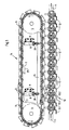
- the release unit 14 comprises rotating members 2, which are mounted on axes 6 Hold swiveling blocks.
- Activation units 8 between the sprockets 4 and 5 intended.
- Each of the activation units 8 is included Circuits 9 provided.
- the activation units 8 are for the Designed using a pressure medium.
- the Activation units 8 pneumatic cylinders or also hydraulic cylinders.
- the Activation units 8 electromagnetic or in connection with an electric motor. Even one Lever bar could be used.
- the activation units 8 are complete by connecting pieces 26 with those in Fig. 2 shown, optionally operable ramps 15, 16 and 17th connected.
- Each pivotable block 1 is on with its respective axis mounted on the rotating member 2 and has a respective one Projection 18, 19 or 20. For simplicity, only that is Projection 18 shown in Fig. 1. These projections 18, 19th or 20 cause certain of the pivotable to pivot Blocks 1 while these are below the optionally operable Ramps 15, 16 and 17 pass depending on which protrusions be contacted by the ramps.
- each block 1 has a bore, in which the respective axis 6 is mounted. So can rotate each block 1 freely around its axis 6.
- Axis 6 is by parts 6.1 and 6.2 on a rotating link 2 stored.
- the blocks 1 made of lightweight material made so that the weight of a block 1 is not is sufficient to cause the product holder 12 to Products without the additional, from ramps 15, 16 or 17 release generated power.
- the pivotable blocks 1 are mounted on their axes 6 so that this during the movement by a horizontal Movement section above the conveyor 10 in a horizontal Position remain. As will be apparent to those skilled in the art if this could be achieved in a variety of ways, e.g. by torsion on the axles or by Balancing the blocks with weights attached and / or the position of the axes could be regulated.
- the swiveling blocks 1, which by the optional actuatable ramps 15, 16 and 17 are pivotable arranged above a conveyor 10.
- the conveyor 10 includes identically constructed product holder 12, which are continuously transported in the conveying direction 11.
- the product holder 12 can each by one associated actuator 13 are activated.
- Such a Adjusting mechanism 13 can be an adjustable pin 13.1 movable gripper part 13.2 and a fixed Stop 13.3 included.
- On the adjustable pin 13.1, which moves downwards through a pivotable block 1 a movable gripper part 13.2 is attached, that interacts with the pen 13.1.
- a group pivotable blocks 1 by an optionally operable ramp is activated - e.g. through the ramp 15 - then the Contact between the movable gripper part 13.2 and the fixed stop 13.3 by the movement of the adjustable pin 13.1 interrupted, and the seized Product is released.
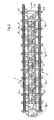
- the rotating links 2 are here as 3 chains shown consisting of chain links.
- the Chain links 3 hold parts 6.1 and 6.2, whereupon the axes 6 of the pivotable blocks 1 are mounted.
- Blocks 1, which are rotatably mounted on the respective axes 6 are in different block types divided.
- a first block type has protrusions 19 in the middle and first ones outer protrusions 20.
- every sixth belongs to the pivotable blocks 1 to the first block type 21.
- This second block type 22 has second outer protrusions 18.
- a third block type 23 which is only the first has outer protrusions.
- a fourth block type 24 (the fourth block of left in Fig. 2), which middle projections 19 and second has outer projections 18.
- the pivotable blocks 1 are in block type grouped in a mirror image arrangement.
- the Blocks are arranged as follows: block type 21, Block type 22, block type 23, block type 24, block type 23, Block type 22, block type 21, block type 22, etc. along the total orbit of the rotating links 2.
- Fig. 2 are below the different groups of pivotable blocks 21, 22, 23 and 24 the matching adjustable pins 13.1 the identical activation mechanisms 13 of the product holders 12 indicated in broken lines.
- the optionally operable first ramp 15 through the activation unit 8 is activated.
- the pivotable blocks 1, which below the first ramp 15 have a projection, deflected.
- the second block type has 22 and the fourth block type 24 each second outer projections 18 which are below the first optionally operable ramp 15 are positioned.
- a lowering of the first optionally operable leads Ramp 15 to deflect the pivotable blocks 22 and 24 and ultimately one to open every second Product holder 12, as shown in Fig. 1.
- the opening of every second below the Release unit 14 passing product holder 12 can also be realized in an alternative way.
- the Actuation of the second optionally operable ramp 17 causes lowering of the first block type 21 and the third block type 23. These each have first outer ones Projections 20 which are optional below the second actuatable ramp 17 are positioned. In this way also a release of every second one Product holder 12 taken products take place.
- the actuation of a third optionally operable ramp 16 causes the release of every third of them Product holders seized products.
- the first block type 21 and the fourth block type 24 are each with a middle one Projection 19 provided, optionally below the third actuatable ramp 16 is positioned. Since every third of the pivotable blocks on the rotating links 2 one of the belongs to both block types 21 and 24, by the Operation of the third selectable ramp 16 each third product will be released.
Landscapes
- Engineering & Computer Science (AREA)
- Mechanical Engineering (AREA)
- Specific Conveyance Elements (AREA)
- Supplying Of Containers To The Packaging Station (AREA)
- Discharge Of Articles From Conveyors (AREA)
- Feeding Of Articles By Means Other Than Belts Or Rollers (AREA)
- Folding Of Thin Sheet-Like Materials, Special Discharging Devices, And Others (AREA)
Claims (17)
- Dispositif pour relâcher des produits transportés sur un transporteur, comprenant
une unité de relâchement (14) munie d'organes tournants (2),
caractérisé en ce qu'à ces organes sont reliés une pluralité de blocs pivotants (1), chacun des blocs pivotants (1) présentant une ou plusieurs saillie(s) (18, 19, 20) ;il est prévu un transporteur (10) qui fait passer une pluralité de supports de produit identiques (12) au droit de l'unité de relâchement (14), chacun des supports de produit (12) étant associé à un des blocs pivotants (1), pendant que le transporteur (10) fait passer les supports de produit (12) au droit de l'unité de relâchement (14) ;il est prévu une pluralité de rampes sélectivement activables (15, 16, 17) associées à l'unité de relâchement (14), chacune des rampes sélectivement activables étant en relation fonctionnelle avec celles des saillies (18, 19, 20) qui ont été sélectionnées ;l'activation de chaque rampe sélectivement activable (15, 16, 17) s'effectue, de sorte que la rampe (15, 16, 17) entre en contact avec ses saillies sélectionnées (18, 19, 20) et de sorte que les blocs (1) passent au droit des rampes (15, 16, 17) activées et que les blocs qui présentent des saillies (18, 19, 20) correspondant aux rampes (15, 16, 17) activées pivotent et que le pivotement des blocs (1) amène les supports de produit (12) qui leur sont associés à relâcher les produits. - Dispositif selon la revendication 1,
caractérisé
en ce que les rampes sélectivement activables (15, 16, 17) sont disposées à un certain espacement mutuel, ceci dans la direction perpendiculaire à la direction (11) du mouvement du transporteur (10). - Dispositif selon la revendication 1,
caractérisé
en ce que les rampes sélectivement activables (15, 16, 17) sont disposées à un certain espacement mutuel, ceci dans la direction (11) du mouvement du transporteur (10). - Dispositif selon la revendication 1,
caractérisé
en ce que chacune des rampes sélectivement activables (15, 16, 17) est reliée à une unité d'activation (8) par au moins un élément de liaison (26). - Dispositif selon la revendication 1,
caractérisé
en ce que la pluralité de blocs (1) est constituée par une pluralité de différents types de blocs (21, 22, 23, 24). - Dispositif selon la revendication 5,
caractérisé
en ce qu'un premier type de blocs (21) de la pluralité de différents types de blocs présente une saillie centrale (19) et une première saillie extérieure (20). - Dispositif selon la revendication 5,
caractérisé
en ce qu'un deuxième type de blocs (22) de la pluralité de différents types de blocs présente une deuxième saillie extérieure (18). - Dispositif selon la revendication 5,
caractérisé
en ce qu'un troisième type de blocs (23) de la pluralité de différents types de blocs présente une première saillie extérieure (20). - Dispositif selon la revendication 5,
caractérisé
en ce qu'un quatrième type de blocs (24) de la pluralité de différents types de blocs présente une saillie centrale (19) et une deuxième saillie extérieure (18). - Dispositif selon la revendication 5,
caractérisé
en ce qu'un premier type de blocs (21) et un troisième type de blocs (23) de la pluralité de différents types de blocs présentent chacun une première saillie extérieure (20) ; et en ce qu'une première rampe extérieure sélectivement activable (15) de la pluralité de rampes sélectivement activables est disposée en relation fonctionnelle avec les premières saillies extérieures (20). - Dispositif selon la revendication 5,
caractérisé
en ce qu'un premier type de blocs (21) et un quatrième type de blocs (24) de la pluralité de différents types de blocs présentent chacun une saillie centrale (19) ; et en ce qu'une rampe centrale sélectivement activable (16) de la pluralité de rampes activables est disposée en relation fonctionnelle avec les saillies centrales (19). - Dispositif selon la revendication 5,
caractérisé
en ce qu'un deuxième type de blocs (21) et un quatrième type de blocs (24) de la pluralité de différents types de blocs présentent chacun une deuxième saillie extérieure (18) et en ce qu'une deuxième rampe extérieure sélectivement activable (17) de la pluralité de rampes activables est disposée en relation fonctionnelle avec les deuxièmes saillies extérieures (18). - Dispositif selon la revendication 10,
caractérisé
en ce qu'un sur deux des blocs de la pluralité de blocs (1) est un bloc du premier ou du troisième type de blocs précité (21, 23), de sorte qu'une activation de la première rampe extérieure sélectivement activable (15) détermine le relâchement d'un produit plié d'un sur deux des supports de produit (12). - Dispositif selon la revendication 11,
caractérisé
en ce qu'un sur deux des blocs de la pluralité de blocs (1) est un bloc du deuxième ou du quatrième type de blocs précités (22, 24), de sorte qu'une activation de la deuxième rampe extérieure sélectivement activable (17) détermine le relâchement d'un produit plié de l'autre des un sur deux des supports de produit (12). - Dispositif selon la revendication 12,
caractérisé
en ce qu'un sur trois des blocs de la pluralité de blocs (1) est un bloc du premier ou du quatrième type de blocs (21, 24), de sorte qu'une activation de la rampe centrale sélectivement activable (16) détermine le relâchement d'un produit plié d'un sur trois des supports de produit (12). - Dispositif selon la revendication 5,
caractériséen ce qu'un premier type de blocs (21) et un troisième type de blocs (23) de la pluralité de différents types de blocs présentent une première saillie extérieure (20) et chaque bloc (1) de rang impair est un bloc du premier ou du troisième type de blocs (21, 23) ;en ce qu'un deuxième type de blocs (22) et un quatrième type de blocs (24) de la pluralité de différents types de blocs présentent une deuxième saillie extérieure (18) et chaque bloc (1) de rang pair est un bloc du deuxième ou quatrième type de blocs (22, 24) ;en ce qu'une première rampe extérieure sélectivement activable (15) de la pluralité de rampes sélectivement activables est disposée en relation fonctionnelle avec les premières saillies extérieures (20) ;en ce qu'une deuxième rampe extérieure sélectivement activable (17) de la pluralité de rampes sélectivement activables est disposée en relation fonctionnelle avec les deuxièmes saillies extérieures (18) ;en ce que l'activation des deux première et deuxième rampes extérieures sélectivement activables (15, 17) détermine un relâchement du produit plié de chacun des supports de produit (12) ; eten ce que l'activation d'une seule des première et deuxième rampes extérieures sélectivement activables (15, 17) détermine le relâchement d'un produit plié d'un sur deux des supports de produit (12). - Dispositif selon la revendication 16,
caractériséen ce qu'un premier type de blocs (21) et un quatrième type de blocs (24) de la pluralité de différents types de blocs présentent chacun une saillie centrale (19) et qu'un sur trois des blocs (1) est un bloc du premier ou du quatrième type de blocs (21, 24) ;en ce qu'une rampe centrale sélectivement activable (16) de la pluralité de rampes sélectivement activables est disposée en relation fonctionnelle avec les saillies centrales (19) ; eten ce que l'activation de la rampe centrale sélectivement activable (16) détermine le relâchement d'un produit plié d'un sur trois des supports de produit (12).
Applications Claiming Priority (2)
| Application Number | Priority Date | Filing Date | Title |
|---|---|---|---|
| US08/349,110 US5501443A (en) | 1994-12-02 | 1994-12-02 | Device for the release of folded products |
| US349110 | 1994-12-02 |
Publications (3)
| Publication Number | Publication Date |
|---|---|
| EP0714844A2 EP0714844A2 (fr) | 1996-06-05 |
| EP0714844A3 EP0714844A3 (fr) | 1997-05-07 |
| EP0714844B1 true EP0714844B1 (fr) | 2000-05-24 |
Family
ID=23370956
Family Applications (1)
| Application Number | Title | Priority Date | Filing Date |
|---|---|---|---|
| EP95117753A Expired - Lifetime EP0714844B1 (fr) | 1994-12-02 | 1995-11-10 | Dispositif pour libérer des produits pliés |
Country Status (6)
| Country | Link |
|---|---|
| US (1) | US5501443A (fr) |
| EP (1) | EP0714844B1 (fr) |
| JP (1) | JPH08225146A (fr) |
| AT (1) | ATE193269T1 (fr) |
| CA (1) | CA2163911A1 (fr) |
| DE (2) | DE19540711C2 (fr) |
Families Citing this family (4)
| Publication number | Priority date | Publication date | Assignee | Title |
|---|---|---|---|---|
| US6067883A (en) * | 1997-08-13 | 2000-05-30 | Heidelberger Druckmaschinen Ag | Method and apparatus for providing positive control of a printable medium in a printing system |
| US6213459B1 (en) | 1998-07-10 | 2001-04-10 | Heidelberger Druckmaschinen Ag | Signature gripper and delivery device |
| US20070034488A1 (en) * | 2005-08-09 | 2007-02-15 | Tuan-Mei Chiu Chen | Roller-type conveying machine |
| DE102008024586A1 (de) * | 2008-05-21 | 2009-11-26 | Beumer Maschinenfabrik Gmbh & Co. Kg | Sortiersystem mit einem Vertikalsorter |
Family Cites Families (13)
| Publication number | Priority date | Publication date | Assignee | Title |
|---|---|---|---|---|
| US2344596A (en) * | 1942-05-20 | 1944-03-21 | Alfred R Carmina | Gauging and sorting machine |
| US3610579A (en) * | 1969-05-01 | 1971-10-05 | Adamovske Strojirny Np | Mechanism for release of paper sheets for stacking purpose |
| US3713648A (en) * | 1970-09-14 | 1973-01-30 | Bobst Champlain Inc | Conveyor for cards and the like |
| CH648261A5 (de) * | 1980-09-16 | 1985-03-15 | Ferag Ag | Vorrichtung zum herausloesen von mittels eines foerderers gefoerderten druckprodukten aus dem foerderstrom. |
| CH669171A5 (de) * | 1985-08-29 | 1989-02-28 | Ferag Ag | Vorrichtung zum uebernehmen und wegfuehren von gefalzten druckbogen von einer foerdereinrichtung. |
| DE3603781A1 (de) * | 1986-02-06 | 1987-08-13 | Roland Man Druckmasch | Vorrichtung zur uebernahme und zum weitertransport von falzprodukten |
| DE3621820A1 (de) * | 1986-06-28 | 1988-01-07 | Roland Man Druckmasch | Falz- und transportvorrichtung |
| DE3621834C1 (de) * | 1986-06-28 | 1987-09-17 | Roland Man Druckmasch | Transportvorrichtung fuer Falzprodukte |
| DE3861306D1 (de) * | 1987-07-21 | 1991-01-31 | Ferag Ag | Transporteur fuer flaechige erzeugnisse, insbesondere druckprodukte. |
| US5168977A (en) * | 1991-06-05 | 1992-12-08 | Fps Food Processing Systems B.V. | Release mechanism |
| SE9103290L (sv) * | 1991-11-07 | 1993-05-08 | Wamag Idab Ab | Foerfarande och anordning foer att oeppna en sjaelvstaengande gripare paa en griparetransportoer |
| US5244078A (en) * | 1992-03-17 | 1993-09-14 | Graphic Management Associates, Inc. | Selective gripper release |
| SE502958C2 (sv) * | 1994-08-19 | 1996-02-26 | Sten Wallsten Ind Ab | Anordning för avlämnande av utvalda exemplar av föremål från en transportbana |
-
1994
- 1994-12-02 US US08/349,110 patent/US5501443A/en not_active Expired - Fee Related
-
1995
- 1995-11-02 DE DE19540711A patent/DE19540711C2/de not_active Expired - Fee Related
- 1995-11-10 DE DE59508389T patent/DE59508389D1/de not_active Expired - Fee Related
- 1995-11-10 EP EP95117753A patent/EP0714844B1/fr not_active Expired - Lifetime
- 1995-11-10 AT AT95117753T patent/ATE193269T1/de not_active IP Right Cessation
- 1995-11-28 CA CA002163911A patent/CA2163911A1/fr not_active Abandoned
- 1995-12-01 JP JP7314253A patent/JPH08225146A/ja active Pending
Also Published As
| Publication number | Publication date |
|---|---|
| DE19540711C2 (de) | 1998-02-12 |
| JPH08225146A (ja) | 1996-09-03 |
| DE19540711A1 (de) | 1996-06-05 |
| EP0714844A2 (fr) | 1996-06-05 |
| US5501443A (en) | 1996-03-26 |
| DE59508389D1 (de) | 2000-06-29 |
| ATE193269T1 (de) | 2000-06-15 |
| EP0714844A3 (fr) | 1997-05-07 |
| CA2163911A1 (fr) | 1996-06-03 |
Similar Documents
| Publication | Publication Date | Title |
|---|---|---|
| DE3041723C2 (de) | Verfahren und Vorrichtung zum Befördern von Stapeln aus bahnförmigen Einheiten | |
| EP0911291A2 (fr) | Dispositif de pliage dans une machine plieuse à grande vitesse | |
| DE3700959C2 (de) | Bogensammelvorrichtung | |
| EP0473902B1 (fr) | Dispositif d'agrafage de produits imprimés composés | |
| EP1034924A1 (fr) | Dispositif pour manipulation de produits | |
| EP0656307B1 (fr) | Cylindre de transport de cahiers | |
| EP0754642B1 (fr) | Méthode et dispositif de sortie de produits en forme de feuille | |
| EP0897890B1 (fr) | Procédé et dispositif pour produire un courant de produits tournés avec une pince de préhension de coin | |
| DE69702107T2 (de) | Entnahme von Druckbogen-Proben | |
| EP0210494B1 (fr) | Dispositif de rassemblement pour feuilles pliées | |
| DE19621331B4 (de) | Vorrichtung zur Aufteilung eines Produktstroms | |
| EP1103503A2 (fr) | Système de transport à poches pour produits imprimés | |
| DE2407752A1 (de) | Verfahren und vorrichtung zum auslegen von bogen | |
| EP0714844B1 (fr) | Dispositif pour libérer des produits pliés | |
| EP0307889A2 (fr) | Dispositif pour émettre des imprimés à partir des roues à aubes d'une plieuse | |
| DE10354673A1 (de) | Vorrichtung zum Aussondern von Bogen aus dem Ausleger einer Bogenrotationsdruckmaschine | |
| EP1118563B1 (fr) | Sytème de préhension à vitesse variable | |
| EP0827930B1 (fr) | Dispositif pour transporter des produits plats imprimés | |
| DE2417614B2 (de) | Vorrichtung zum auslegen von produkten an einer rollenrotationsdruckmaschine | |
| DE19736822A1 (de) | Vorrichtung zum Zusammentragen von Signaturen | |
| DD236503A1 (de) | Foerdereinrichtung zur wahlweisen 180 hoch grad-drehung von buechern oder buchblocks | |
| DE69708026T2 (de) | Mechanismus zum Öffnen und Schliessen von Greifern eines Bogentransportzylinders in einer Bogendruckmaschine | |
| DE19642130C2 (de) | Einrichtung zur Übergabe von Druckprodukten | |
| DE10315822A1 (de) | Drehbare Signaturenübergabevorrichtung | |
| EP1074495A1 (fr) | Dispositif de transport |
Legal Events
| Date | Code | Title | Description |
|---|---|---|---|
| PUAI | Public reference made under article 153(3) epc to a published international application that has entered the european phase |
Free format text: ORIGINAL CODE: 0009012 |
|
| 17P | Request for examination filed |
Effective date: 19951110 |
|
| AK | Designated contracting states |
Kind code of ref document: A2 Designated state(s): AT CH DE FR GB IT LI |
|
| PUAL | Search report despatched |
Free format text: ORIGINAL CODE: 0009013 |
|
| AK | Designated contracting states |
Kind code of ref document: A3 Designated state(s): AT CH DE FR GB IT LI |
|
| GRAG | Despatch of communication of intention to grant |
Free format text: ORIGINAL CODE: EPIDOS AGRA |
|
| GRAG | Despatch of communication of intention to grant |
Free format text: ORIGINAL CODE: EPIDOS AGRA |
|
| GRAH | Despatch of communication of intention to grant a patent |
Free format text: ORIGINAL CODE: EPIDOS IGRA |
|
| 17Q | First examination report despatched |
Effective date: 19990920 |
|
| GRAH | Despatch of communication of intention to grant a patent |
Free format text: ORIGINAL CODE: EPIDOS IGRA |
|
| GRAA | (expected) grant |
Free format text: ORIGINAL CODE: 0009210 |
|
| AK | Designated contracting states |
Kind code of ref document: B1 Designated state(s): AT CH DE FR GB IT LI |
|
| REF | Corresponds to: |
Ref document number: 193269 Country of ref document: AT Date of ref document: 20000615 Kind code of ref document: T |
|
| REG | Reference to a national code |
Ref country code: CH Ref legal event code: EP |
|
| REF | Corresponds to: |
Ref document number: 59508389 Country of ref document: DE Date of ref document: 20000629 |
|
| ITF | It: translation for a ep patent filed | ||
| GBT | Gb: translation of ep patent filed (gb section 77(6)(a)/1977) |
Effective date: 20000717 |
|
| ET | Fr: translation filed | ||
| PG25 | Lapsed in a contracting state [announced via postgrant information from national office to epo] |
Ref country code: GB Free format text: LAPSE BECAUSE OF NON-PAYMENT OF DUE FEES Effective date: 20001110 Ref country code: AT Free format text: LAPSE BECAUSE OF NON-PAYMENT OF DUE FEES Effective date: 20001110 |
|
| PLBE | No opposition filed within time limit |
Free format text: ORIGINAL CODE: 0009261 |
|
| STAA | Information on the status of an ep patent application or granted ep patent |
Free format text: STATUS: NO OPPOSITION FILED WITHIN TIME LIMIT |
|
| 26N | No opposition filed | ||
| GBPC | Gb: european patent ceased through non-payment of renewal fee |
Effective date: 20001110 |
|
| PGFP | Annual fee paid to national office [announced via postgrant information from national office to epo] |
Ref country code: FR Payment date: 20021119 Year of fee payment: 8 |
|
| PGFP | Annual fee paid to national office [announced via postgrant information from national office to epo] |
Ref country code: CH Payment date: 20021126 Year of fee payment: 8 |
|
| PGFP | Annual fee paid to national office [announced via postgrant information from national office to epo] |
Ref country code: DE Payment date: 20021128 Year of fee payment: 8 |
|
| PG25 | Lapsed in a contracting state [announced via postgrant information from national office to epo] |
Ref country code: LI Free format text: LAPSE BECAUSE OF NON-PAYMENT OF DUE FEES Effective date: 20031130 Ref country code: CH Free format text: LAPSE BECAUSE OF NON-PAYMENT OF DUE FEES Effective date: 20031130 |
|
| PG25 | Lapsed in a contracting state [announced via postgrant information from national office to epo] |
Ref country code: DE Free format text: LAPSE BECAUSE OF NON-PAYMENT OF DUE FEES Effective date: 20040602 |
|
| REG | Reference to a national code |
Ref country code: CH Ref legal event code: PL |
|
| PG25 | Lapsed in a contracting state [announced via postgrant information from national office to epo] |
Ref country code: FR Free format text: LAPSE BECAUSE OF NON-PAYMENT OF DUE FEES Effective date: 20040730 |
|
| REG | Reference to a national code |
Ref country code: FR Ref legal event code: ST |
|
| PG25 | Lapsed in a contracting state [announced via postgrant information from national office to epo] |
Ref country code: IT Free format text: LAPSE BECAUSE OF NON-PAYMENT OF DUE FEES Effective date: 20051110 |