EP0715083A2 - Vérin à piston sans tige - Google Patents
Vérin à piston sans tige Download PDFInfo
- Publication number
- EP0715083A2 EP0715083A2 EP95890207A EP95890207A EP0715083A2 EP 0715083 A2 EP0715083 A2 EP 0715083A2 EP 95890207 A EP95890207 A EP 95890207A EP 95890207 A EP95890207 A EP 95890207A EP 0715083 A2 EP0715083 A2 EP 0715083A2
- Authority
- EP
- European Patent Office
- Prior art keywords
- cylinder
- pressure medium
- damping
- longitudinal slot
- cylinder housing
- Prior art date
- Legal status (The legal status is an assumption and is not a legal conclusion. Google has not performed a legal analysis and makes no representation as to the accuracy of the status listed.)
- Granted
Links
- 239000012530 fluid Substances 0.000 title description 2
- 238000007789 sealing Methods 0.000 claims abstract description 43
- 230000007704 transition Effects 0.000 claims abstract description 3
- 238000013016 damping Methods 0.000 claims description 50
- 238000009795 derivation Methods 0.000 claims 2
- 230000005540 biological transmission Effects 0.000 description 2
- 230000000694 effects Effects 0.000 description 2
- 238000004873 anchoring Methods 0.000 description 1
- 230000008878 coupling Effects 0.000 description 1
- 238000010168 coupling process Methods 0.000 description 1
- 238000005859 coupling reaction Methods 0.000 description 1
- 238000007599 discharging Methods 0.000 description 1
- 238000009434 installation Methods 0.000 description 1
- 238000004519 manufacturing process Methods 0.000 description 1
- 230000001105 regulatory effect Effects 0.000 description 1
- 238000000926 separation method Methods 0.000 description 1
Images

Classifications
-
- F—MECHANICAL ENGINEERING; LIGHTING; HEATING; WEAPONS; BLASTING
- F15—FLUID-PRESSURE ACTUATORS; HYDRAULICS OR PNEUMATICS IN GENERAL
- F15B—SYSTEMS ACTING BY MEANS OF FLUIDS IN GENERAL; FLUID-PRESSURE ACTUATORS, e.g. SERVOMOTORS; DETAILS OF FLUID-PRESSURE SYSTEMS, NOT OTHERWISE PROVIDED FOR
- F15B15/00—Fluid-actuated devices for displacing a member from one position to another; Gearing associated therewith
- F15B15/08—Characterised by the construction of the motor unit
- F15B15/082—Characterised by the construction of the motor unit the motor being of the slotted cylinder type
Definitions
- the invention relates to a rodless pressure medium cylinder with a cylinder housing, which is provided with a continuous longitudinal slot over its length and has a cylindrical interior in which a drive piston is arranged to be longitudinally displaceable, from which a lateral approach for power output through the longitudinal slot to the outside is, and with the cylindrical interior of the cylinder housing at its ends closing cylinder covers, on the outside of which a connection is provided for the supply and discharge of the pressure piston actuating the pressure piston, the longitudinal slot being sealable by an inner sealing tape provided in the interior of the cylinder housing, which is lifted from the longitudinal slot only in the area of the attachment and is guided through a guide channel in the drive piston, and is at most closed off to the outside by an additional outer sealing tape which is on the outside of the cylinder housing ses is attached at the ends of the longitudinal slot by clamping pieces separated from the cylinder covers.
- a pressure medium cylinder of this type is known from US 5,245,910 A.
- the outer sealing tape which covers the longitudinal slot on the outside of the cylinder housing, is anchored at both ends in this known embodiment at each end by a clamping piece separate from the cylinder cover, which is fastened to the cylinder housing with two screws and has a threaded bore for connecting one Pressure fluid line is determined.
- the threaded bore leads into the space between the outer and the inner sealing tape, which extends to the covers, where a seal is inserted between the clamping piece holding the outer sealing tape and the inner sealing tape in the longitudinal slot.
- the longitudinal slot is thereby sealed, so that it is possible to create a vacuum or an overpressure in the space between the two sealing tapes with respect to that surrounding the pressure medium cylinder Generate space.
- Pressure medium cylinders such as pneumatic or hydraulic cylinders
- the connections lie transversely to the axis of the pressure medium cylinder, horizontally starting in the end caps of the cylinder.
- the invention has for its object to improve the known rodless cylinder of the type mentioned so that the connections for the supply and discharge of the pressure medium can be provided on any side of the cylinder from the cylinder cover in a simple manner and without changing the cover .
- the invention solves this problem in that the inner sealing tape is anchored at its ends in each case by a clamping piece separate from the cylinder cover in or on the longitudinal slot and the two cylinder covers can be fastened to the cylinder housing in different positions rotated relative to one another in the plane of the cylinder cover, and that the channels transmitting the pressure medium in the two cylinder covers are arranged rotationally symmetrically in the transition region between the cylinder cover and the adjacent component of the cylinder housing.
- the clamping pieces with which the sealing tapes are attached to or in the longitudinal slot of the cylinder housing can be inserted into the longitudinal slot near the ends of the cylinder housing and can be held in place by widening clamping screws by means of a wedge effect on the walls of the longitudinal slot.
- the inner sealing tape which seals the longitudinal slot in the area of the pressurized cylinder chamber, can be positively attached to the clamping pieces, and an external sealing tape, which is provided if necessary, and which only covers the longitudinal slot to the outside, can be non-positively attached to the clamping pieces. These are located in a relatively narrow dead area directly at the end of the cylinder housing. It is the same area in which the airtight seal of the cylinder housing takes place.
- the respective clamping piece presses against the walls of the longitudinal slot by means of a wedge effect and thus brings about a secure anchoring of both the inner and the outer sealing tape. Since the clamping piece is axially displaceable in the longitudinal slot, the belt tension can be easily adapted to the respective requirements.
- the cylinder covers which are preferably polygonal, e.g. square or rectangular cross-section are pressed against the cylinder housing by centrally symmetrically arranged tension screws running parallel to the axis of the cylinder housing.
- the cylinder covers can be centered on a cylinder surface of the cylinder housing and can be freely rotatable coaxially to the cylinder surface. It is then possible to set the two cylinder covers with the connections for the pressure medium in any desired position.
- a further development of this embodiment provides that the cylinder covers are attached to the cylinder housing by holding frames which act on them and which can be rotated relative to them, on which tension bolts engage which press the cylinder covers onto the cylinder housing.
- this can advantageously also be applied to a rodless pressure medium cylinder which is provided with end position damping for the drive piston.
- the end position damping consists of damping pins protruding into the ends of the cylinder housing in the axial direction with a central channel for supplying and discharging the pressure medium.
- the damping pins cooperate with damping cylinders in the end faces of the drive piston, which close the central channel when a damping pin penetrates, at least one damping channel being provided to the side of the damping pin, which opens into the pressure medium connection via a throttle adjustable by a damping screw.
- the damping screw for adjusting the throttle is arranged on the same side of the cover as the pressure medium connection and runs with its axis approximately in the same direction as the pressure medium connection, with a connecting channel being arranged between the damping channel and the throttle Cylinder cover runs rotationally symmetrical, preferably concentrically surrounds the central bore.
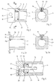
- FIG. 1 shows a longitudinal section through the rodless pressure medium cylinder according to the invention
- FIG. 2 shows a somewhat larger sectional view of one end of the pressure medium cylinder
- FIG. 3 shows a section along the line III-III in FIG. 2
- FIG. 2a shows a comparison with FIG 2 a slightly modified version of the cylinder housing without cylinder cover
- FIG. 3a a section analogous to FIG. 3 along the line IIIa-IIIa in FIG. 2a
- 4 shows the end of a pressure medium cylinder in a slightly modified design in an axial longitudinal section
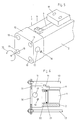
- FIG. 5 shows a perspective view of the cylinder end
- FIG. 6 shows the cylinder end of another exemplary embodiment in a partially sectioned side view.
- the pressure medium cylinder 1 consists of a cylinder housing 2 which has a cylindrical interior 3 in which a drive piston 4 can be displaced.
- the drive piston 4 is sealed at its ends by seals 5 in the cylindrical interior 3 and divides it into two pressure chambers which are independent of one another and not connected to one another on both sides of the drive piston 4.
- the cylinder housing 2 is provided with a longitudinal slot 6 which is continuous over its entire length. This is sealed in the area of the two pressure chambers of the cylindrical interior 3 by sealing tapes, etc. by an inner sealing tape 7 and an outer sealing tape 8, which essentially covers the longitudinal slot 6 to the outside. 1, a lateral extension 9 is attached to the drive piston 4, which is led through the longitudinal slot 6 out of the cylinder housing 2 and ends in the exemplary embodiment with a connecting flange 10. The driving force of the pressure medium cylinder 1 is taken off via this connecting flange 10 and the coupling takes place with a machine part to be driven by the pressure medium cylinder 1.
- the two sealing tapes, the inner sealing tape 7 and the outer sealing tape 8, are fastened to each end of the cylinder housing 2 by a clamping piece 11 on or in the longitudinal slot 6.
- the clamping pieces 11 are located directly on the edge of cylinder covers 12, which are pressed against the cylinder housing 2 in a sealing manner by four lag screws 13.
- a damping pin 14 projects from each cylinder cover 12 against the drive piston 4 in the cylindrical interior 3 of the cylinder housing 2.
- a damping cylinder 15 is provided, which cooperate with the damping pin 14.
- damping screws 18 are also arranged in the two covers 12, which serve to adjust the throttle of a damping device for the end position damping.
- the inner sealing band 7 passes through a guide channel 19 and the outer sealing band 8 is passed through a guide channel 20 likewise provided in the radial shoulder 9.
- the respective Tension of the two sealing tapes 7 and 8 can be regulated by the clamping pieces 11 at their ends, which are correspondingly displaceable in the longitudinal slot 6.
- the clamping pieces 11 are essentially in a dead area from the point of pressure application between the end of the cylinder housing 2 and a seal 21 which is provided on a cylindrical projection 22 which extends from the cover 12 into the cylindrical interior 3 protrudes.
- the essential structure of the clamping pieces 11 can be seen from FIGS. 3 and 3a. 3 each consist of a housing 23 and a clamping wedge 24 which is drawn into a wedge-shaped recess of the housing 23 by means of a clamping screw 25 and spreads and clamps it against the side walls of the longitudinal slot 6.
- the housing 23 of the clamping pieces 11 is fastened to the longitudinal slot 6 by means of a clamping screw 25 and a nut 25a.
- the inner sealing tape 7 extends to the ends of the cylinder housing 2 and, according to FIGS. 2 and 3, is held in a form-fitting manner by the bolt of the clamping screw 25, onto which it is attached with an opening. 2a and 3a, the end of the inner sealing tape 7 is additionally clamped against the longitudinal slot 6 by the nut 25a of the clamping screw 25.
- the outer sealing tape 8 is somewhat shorter than the inner sealing tape 7 and is clamped on the clamping piece 11 or between the latter and the cylinder housing 2 by its own holding device 11a.
- the cylinder housing 2 is closed at its ends by covers 12, which are held by lag screws (not shown).
- the illustrated cover 12 is followed in this case by an extension 22 which is separate from the cover 12 and which projects into the cylindrical interior 3 and seals it with a seal 21.
- a projection 14 protrudes from the extension 22, which cooperates with a damping cylinder, not shown, of the drive piston, also not shown.
- the damping pin 14 has a central channel 16, which is connected to the connection 17.
- Parallel to the central channel 16 of the damping pin 14, a damping channel 26 passes through the shoulder 22 and connects the cylindrical interior 3 with a connecting channel 27 in the cover 12.
- This connecting channel 27 runs in the cover 12 in a rotationally symmetrical manner and leads to a throttle via a connecting hole 28 provided in the cover 12 29, which can be adjusted by means of the damping screw 18.
- the throttle 29 is connected to the connection 17.
- the mode of operation of the invention can easily be illustrated on the basis of the schematic illustration in FIG. 5.
- the cover 12 shown in FIG. 5 is rectangular and is held on the cylinder housing 2 with the aid of four parallel, centrally symmetrically arranged and only indicated tension screws 13.
- the connection 17 for the supply and discharge of the pressure medium actuating the pressure medium cylinder 1 and the damping screw 18 for the end position damping are located on the front side of the cover 12.
- the longitudinal slot 6 is located at the top in the middle of the cylinder housing 2, where the connecting flange 10 is provided for the power transmission to the device to be driven. The position of the connecting flange 10 and thus also of the cylinder housing 2 is predetermined by this power transmission connection.
- connection 17 and the damping screw 18 are located on the top of the pressure cylinder 1.
- connection 17 and the damping screw 18 are located 18 on the hidden back of the pressure cylinder 1.
- connection 17 for the pressure medium supply and with this also the damping screw 18 can be quickly and easily moved to the most accessible side of the pressure medium cylinder 1.
- the cover 12 is not only square, but also rectangular, and can have any polygonal shape. It is only essential that the cover is not used for tightening the sealing tapes and that both the tension screws 13 and the channel guide are arranged or executed centrally symmetrically inside the cover, which is the basic condition represents the correct rotatability of the lid. Finally, the cover can also be cylindrical.
- FIG. 6 An exemplary embodiment of this variant of the invention is shown in FIG. 6.
- the cover 12 is cylindrical there and projects with a cylindrical extension 22 into the cylindrical interior 3, against which it is sealed by means of a seal 21.
- the two sealing tapes, not shown, are also fastened here by clamping pieces 11.
- the two lids themselves are held on the cylinder housing 2 by means of lag screws 13, the number of lag screws 13, their position and their design being arbitrary.
- the function of the lag screws can also be carried out by parts of the machine frame in which the cylinder as a whole is installed.
- the tension screws 13 engage on a holding frame 31 provided behind the cover 12, in which the cover 12 is rotatably mounted by means of a centrally projecting cylindrical projection 32.
- the cover 12 can be rotated continuously about its axis in both directions in this embodiment, so that the connection 17 for the pressure medium together with the damping screw 18 can be continuously adjusted to any position.
- the prerequisite here is again that the sealing tapes are not fastened by the cover 12, but by their own clamping pieces 11 and that the channel guides in the interior of the cover 12 are designed to be rotationally symmetrical.
- a particular advantage for the user is the possibility of installing the cover in a horizontal or vertical, i.e. right-angled position to the machine frame, while the side attachment with the connecting flange is in a relatively oblique shape between 0 and 90 °, depending on Starting point of view, can be arranged.
- This inclined drive position can usually help to solve difficult space conditions or force applications.
Landscapes
- Engineering & Computer Science (AREA)
- Physics & Mathematics (AREA)
- Fluid Mechanics (AREA)
- Mechanical Engineering (AREA)
- General Engineering & Computer Science (AREA)
- Actuator (AREA)
- Portable Nailing Machines And Staplers (AREA)
Applications Claiming Priority (3)
| Application Number | Priority Date | Filing Date | Title |
|---|---|---|---|
| AT221994 | 1994-11-30 | ||
| AT0221994A AT402543B (de) | 1994-11-30 | 1994-11-30 | Kolbenstangenloser druckmittelzylinder |
| AT2219/94 | 1994-11-30 |
Publications (3)
| Publication Number | Publication Date |
|---|---|
| EP0715083A2 true EP0715083A2 (fr) | 1996-06-05 |
| EP0715083A3 EP0715083A3 (fr) | 1997-07-23 |
| EP0715083B1 EP0715083B1 (fr) | 2000-09-20 |
Family
ID=3530246
Family Applications (1)
| Application Number | Title | Priority Date | Filing Date |
|---|---|---|---|
| EP95890207A Expired - Lifetime EP0715083B1 (fr) | 1994-11-30 | 1995-11-16 | Vérin à piston sans tige |
Country Status (6)
| Country | Link |
|---|---|
| US (1) | US5606903A (fr) |
| EP (1) | EP0715083B1 (fr) |
| JP (1) | JP3713083B2 (fr) |
| AT (1) | AT402543B (fr) |
| DE (1) | DE59508730D1 (fr) |
| ES (1) | ES2151589T3 (fr) |
Cited By (2)
| Publication number | Priority date | Publication date | Assignee | Title |
|---|---|---|---|---|
| EP0945629A1 (fr) * | 1998-03-27 | 1999-09-29 | Ab Rexroth Mecman | Support de bande d'étanchéité |
| WO2002068827A1 (fr) * | 2001-02-28 | 2002-09-06 | Festo Ag & Co. | Entrainement lineaire sans bielle |
Families Citing this family (17)
| Publication number | Priority date | Publication date | Assignee | Title |
|---|---|---|---|---|
| JP3177949B2 (ja) * | 1997-04-29 | 2001-06-18 | 豊和工業株式会社 | ロッドレスシリンダ |
| JP3818752B2 (ja) * | 1997-09-24 | 2006-09-06 | Smc株式会社 | ロッドレスシリンダ |
| US6257123B1 (en) | 1997-10-24 | 2001-07-10 | Phd, Inc. | Rodless slides |
| US5988042A (en) * | 1997-10-24 | 1999-11-23 | Phd, Inc. | Rodless cylinder with internal bearings |
| SE510854C2 (sv) * | 1997-10-29 | 1999-06-28 | Mecman Ab Rexroth | Anordning vid gavel till en tryckfluidcylinder samt tryckfluidcylinder innefattande en eller två dylika anordningar |
| JP3543592B2 (ja) * | 1997-11-24 | 2004-07-14 | 豊和工業株式会社 | ゴムダンパ |
| JP2001116147A (ja) * | 1999-10-18 | 2001-04-27 | Smc Corp | ロッドレスシリンダのシール構造 |
| DE10049348A1 (de) * | 2000-10-05 | 2002-04-18 | Rexroth Star Gmbh | Linearführungsanordnung |
| JP3704294B2 (ja) * | 2001-04-25 | 2005-10-12 | Smc株式会社 | ベルト固定機構 |
| CN1647525B (zh) * | 2002-04-17 | 2012-12-12 | 汤姆森许可公司 | 分组误差信号产生器 |
| US6857780B2 (en) * | 2002-11-15 | 2005-02-22 | Phd, Inc. | Rodless slide assembly |
| US7290478B2 (en) * | 2005-01-28 | 2007-11-06 | Phd, Inc. | Stop for a slide assembly |
| NZ575249A (en) * | 2009-03-02 | 2011-06-30 | Open Building Solutions Ltd | Re-closable dust cover for track of support carriage of sliding door or window, with carriage constructed as a sliding fastener of cover |
| DE102016014585A1 (de) * | 2016-12-08 | 2018-06-14 | Wirtgen Gmbh | Betätigungseinheit zur Verriegelung eines Bauteils einer Baumaschine und Baumaschine mit einer derartigen Betätigungseinheit |
| US10821856B2 (en) | 2018-12-13 | 2020-11-03 | Ford Global Technologies, Llc | Vehicle cabin |
| CN109737114A (zh) * | 2019-01-07 | 2019-05-10 | 珠海市广源信科技有限公司 | 一种无杆气缸 |
| US10807503B2 (en) | 2019-03-04 | 2020-10-20 | Ford Global Technologies, Llc | Seat track assembly including cover members |
Citations (1)
| Publication number | Priority date | Publication date | Assignee | Title |
|---|---|---|---|---|
| US5245910A (en) | 1991-05-29 | 1993-09-21 | Hygrama Ag | Rodless cylinder |
Family Cites Families (5)
| Publication number | Priority date | Publication date | Assignee | Title |
|---|---|---|---|---|
| US4273031A (en) * | 1979-05-22 | 1981-06-16 | Hannon Albert H | Fluid pressure containment actuator |
| US4373427A (en) * | 1980-01-31 | 1983-02-15 | Tol-O-Matic, Inc. | Fluid pressure cylinder |
| US4838147A (en) * | 1988-01-26 | 1989-06-13 | Grigory Grishchenko | Pressure fluid actuator |
| IT1217812B (it) * | 1988-06-08 | 1990-03-30 | Univers S P A | Dispositivo di tenuta per cilindri pneumatici senz,asta |
| DE4120965A1 (de) * | 1991-06-25 | 1993-01-07 | Knorr Bremse Ag | Zylinder |
-
1994
- 1994-11-30 AT AT0221994A patent/AT402543B/de not_active IP Right Cessation
-
1995
- 1995-11-16 ES ES95890207T patent/ES2151589T3/es not_active Expired - Lifetime
- 1995-11-16 DE DE59508730T patent/DE59508730D1/de not_active Expired - Lifetime
- 1995-11-16 EP EP95890207A patent/EP0715083B1/fr not_active Expired - Lifetime
- 1995-11-29 JP JP31067795A patent/JP3713083B2/ja not_active Expired - Lifetime
- 1995-11-30 US US08/565,244 patent/US5606903A/en not_active Expired - Lifetime
Patent Citations (1)
| Publication number | Priority date | Publication date | Assignee | Title |
|---|---|---|---|---|
| US5245910A (en) | 1991-05-29 | 1993-09-21 | Hygrama Ag | Rodless cylinder |
Cited By (4)
| Publication number | Priority date | Publication date | Assignee | Title |
|---|---|---|---|---|
| EP0945629A1 (fr) * | 1998-03-27 | 1999-09-29 | Ab Rexroth Mecman | Support de bande d'étanchéité |
| WO2002068827A1 (fr) * | 2001-02-28 | 2002-09-06 | Festo Ag & Co. | Entrainement lineaire sans bielle |
| DE10109479A1 (de) * | 2001-02-28 | 2002-09-12 | Festo Ag & Co | Kolbenstangenloser Linearantrieb |
| US6766727B2 (en) | 2001-02-28 | 2004-07-27 | Festo Ag & Co. | Rodless linear drive |
Also Published As
| Publication number | Publication date |
|---|---|
| EP0715083A3 (fr) | 1997-07-23 |
| JPH08219114A (ja) | 1996-08-27 |
| AT402543B (de) | 1997-06-25 |
| DE59508730D1 (de) | 2000-10-26 |
| JP3713083B2 (ja) | 2005-11-02 |
| EP0715083B1 (fr) | 2000-09-20 |
| US5606903A (en) | 1997-03-04 |
| ES2151589T3 (es) | 2001-01-01 |
| ATA221994A (de) | 1996-10-15 |
Similar Documents
| Publication | Publication Date | Title |
|---|---|---|
| AT402543B (de) | Kolbenstangenloser druckmittelzylinder | |
| DE2645723C3 (de) | Rohrweiche, insbesondere für die pneumatische Förderung von Schüttgut | |
| DE3623555C2 (fr) | ||
| DE19604649C2 (de) | Greifvorrichtung bzw. Spannvorrichtung | |
| DE102014112550B4 (de) | Exzenterschneckenpumpe | |
| DE3306526C2 (fr) | ||
| DE2302732A1 (de) | Einstellbare daempfungsvorrichtung | |
| DE102005002597B3 (de) | Leitungsdurchführung | |
| EP1274945A1 (fr) | Cylindre de travail | |
| DE4242601A1 (de) | Kolben-Zylinder-Anordnung | |
| DE3414067A1 (de) | Ueberlastsicherung | |
| DE102008006045B4 (de) | Tablettenpresse | |
| DE9416523U1 (de) | Linearantrieb | |
| DE3320306A1 (de) | Ventilaktuator | |
| EP0209869B1 (fr) | Dispositif pour pivoter l'arbre d'un assemblage antidérapant à centrifuge de véhicules automobiles | |
| EP0350596B1 (fr) | Dispositif pour limiter et ajuster la voie de réglage des armatures | |
| DE19534484C1 (de) | Vorrichtung zur Durchführung von Leitungen durch eine Öffnung in einer Wand | |
| DE9313711U1 (de) | Kraftschrauber | |
| DE3526676A1 (de) | Aus mindestens zwei bauteilen bestehendes hochspannungsschaltgeraet | |
| EP0966610A1 (fr) | Dispositif haute pression | |
| DE3734987C1 (de) | Schneidrotor mit auswechselbaren Messerleisten zum Zerkleinern von festen Materialien | |
| DE102017117601B4 (de) | Freifallausscheider für Fördergut | |
| EP0563821A1 (fr) | Clé hydraulique | |
| DE29912232U1 (de) | Schraubwerkzeug | |
| DE3216371A1 (de) | Druckfestes gehaeuse |
Legal Events
| Date | Code | Title | Description |
|---|---|---|---|
| PUAI | Public reference made under article 153(3) epc to a published international application that has entered the european phase |
Free format text: ORIGINAL CODE: 0009012 |
|
| AK | Designated contracting states |
Kind code of ref document: A2 Designated state(s): CH DE ES FR GB IT LI NL SE |
|
| PUAL | Search report despatched |
Free format text: ORIGINAL CODE: 0009013 |
|
| AK | Designated contracting states |
Kind code of ref document: A3 Designated state(s): CH DE ES FR GB IT LI NL SE |
|
| 17P | Request for examination filed |
Effective date: 19970807 |
|
| GRAG | Despatch of communication of intention to grant |
Free format text: ORIGINAL CODE: EPIDOS AGRA |
|
| 17Q | First examination report despatched |
Effective date: 19991207 |
|
| GRAG | Despatch of communication of intention to grant |
Free format text: ORIGINAL CODE: EPIDOS AGRA |
|
| GRAH | Despatch of communication of intention to grant a patent |
Free format text: ORIGINAL CODE: EPIDOS IGRA |
|
| GRAH | Despatch of communication of intention to grant a patent |
Free format text: ORIGINAL CODE: EPIDOS IGRA |
|
| GRAA | (expected) grant |
Free format text: ORIGINAL CODE: 0009210 |
|
| AK | Designated contracting states |
Kind code of ref document: B1 Designated state(s): CH DE ES FR GB IT LI NL SE |
|
| REG | Reference to a national code |
Ref country code: CH Ref legal event code: NV Representative=s name: ISLER & PEDRAZZINI AG Ref country code: CH Ref legal event code: EP |
|
| GBT | Gb: translation of ep patent filed (gb section 77(6)(a)/1977) |
Effective date: 20000925 |
|
| REF | Corresponds to: |
Ref document number: 59508730 Country of ref document: DE Date of ref document: 20001026 |
|
| ITF | It: translation for a ep patent filed | ||
| ET | Fr: translation filed | ||
| REG | Reference to a national code |
Ref country code: ES Ref legal event code: FG2A Ref document number: 2151589 Country of ref document: ES Kind code of ref document: T3 |
|
| PLBE | No opposition filed within time limit |
Free format text: ORIGINAL CODE: 0009261 |
|
| STAA | Information on the status of an ep patent application or granted ep patent |
Free format text: STATUS: NO OPPOSITION FILED WITHIN TIME LIMIT |
|
| 26N | No opposition filed | ||
| REG | Reference to a national code |
Ref country code: GB Ref legal event code: IF02 |
|
| PGFP | Annual fee paid to national office [announced via postgrant information from national office to epo] |
Ref country code: NL Payment date: 20031031 Year of fee payment: 9 |
|
| PGFP | Annual fee paid to national office [announced via postgrant information from national office to epo] |
Ref country code: ES Payment date: 20031104 Year of fee payment: 9 |
|
| PGFP | Annual fee paid to national office [announced via postgrant information from national office to epo] |
Ref country code: SE Payment date: 20031105 Year of fee payment: 9 |
|
| PGFP | Annual fee paid to national office [announced via postgrant information from national office to epo] |
Ref country code: CH Payment date: 20031120 Year of fee payment: 9 |
|
| PG25 | Lapsed in a contracting state [announced via postgrant information from national office to epo] |
Ref country code: SE Free format text: LAPSE BECAUSE OF NON-PAYMENT OF DUE FEES Effective date: 20041117 Ref country code: ES Free format text: LAPSE BECAUSE OF NON-PAYMENT OF DUE FEES Effective date: 20041117 |
|
| PG25 | Lapsed in a contracting state [announced via postgrant information from national office to epo] |
Ref country code: LI Free format text: LAPSE BECAUSE OF NON-PAYMENT OF DUE FEES Effective date: 20041130 Ref country code: CH Free format text: LAPSE BECAUSE OF NON-PAYMENT OF DUE FEES Effective date: 20041130 |
|
| PG25 | Lapsed in a contracting state [announced via postgrant information from national office to epo] |
Ref country code: NL Free format text: LAPSE BECAUSE OF NON-PAYMENT OF DUE FEES Effective date: 20050601 |
|
| EUG | Se: european patent has lapsed | ||
| REG | Reference to a national code |
Ref country code: CH Ref legal event code: PL |
|
| NLV4 | Nl: lapsed or anulled due to non-payment of the annual fee |
Effective date: 20050601 |
|
| REG | Reference to a national code |
Ref country code: ES Ref legal event code: FD2A Effective date: 20041117 |
|
| REG | Reference to a national code |
Ref country code: GB Ref legal event code: 732E |
|
| REG | Reference to a national code |
Ref country code: FR Ref legal event code: TP |
|
| PGFP | Annual fee paid to national office [announced via postgrant information from national office to epo] |
Ref country code: FR Payment date: 20141119 Year of fee payment: 20 Ref country code: DE Payment date: 20141119 Year of fee payment: 20 Ref country code: GB Payment date: 20141119 Year of fee payment: 20 |
|
| PGFP | Annual fee paid to national office [announced via postgrant information from national office to epo] |
Ref country code: IT Payment date: 20141126 Year of fee payment: 20 |
|
| REG | Reference to a national code |
Ref country code: DE Ref legal event code: R071 Ref document number: 59508730 Country of ref document: DE |
|
| REG | Reference to a national code |
Ref country code: GB Ref legal event code: PE20 Expiry date: 20151115 |
|
| PG25 | Lapsed in a contracting state [announced via postgrant information from national office to epo] |
Ref country code: GB Free format text: LAPSE BECAUSE OF EXPIRATION OF PROTECTION Effective date: 20151115 |