EP0715100B1 - Régulateur de pression d'huile de transmission automatique - Google Patents
Régulateur de pression d'huile de transmission automatique Download PDFInfo
- Publication number
- EP0715100B1 EP0715100B1 EP95118799A EP95118799A EP0715100B1 EP 0715100 B1 EP0715100 B1 EP 0715100B1 EP 95118799 A EP95118799 A EP 95118799A EP 95118799 A EP95118799 A EP 95118799A EP 0715100 B1 EP0715100 B1 EP 0715100B1
- Authority
- EP
- European Patent Office
- Prior art keywords
- pressure
- hydraulic servo
- valve
- oil
- oil pressure
- Prior art date
- Legal status (The legal status is an assumption and is not a legal conclusion. Google has not performed a legal analysis and makes no representation as to the accuracy of the status listed.)
- Expired - Lifetime
Links
- 230000005540 biological transmission Effects 0.000 title claims description 19
- 230000008859 change Effects 0.000 description 17
- 230000002093 peripheral effect Effects 0.000 description 5
- 238000010276 construction Methods 0.000 description 4
- 238000006073 displacement reaction Methods 0.000 description 4
- 230000007246 mechanism Effects 0.000 description 4
- 238000005056 compaction Methods 0.000 description 3
- 238000010586 diagram Methods 0.000 description 3
- 230000000694 effects Effects 0.000 description 3
- 238000005516 engineering process Methods 0.000 description 3
- 230000001105 regulatory effect Effects 0.000 description 3
- 230000004044 response Effects 0.000 description 3
- 230000008901 benefit Effects 0.000 description 2
- 239000000969 carrier Substances 0.000 description 2
- 230000000593 degrading effect Effects 0.000 description 1
- 230000004048 modification Effects 0.000 description 1
- 238000012986 modification Methods 0.000 description 1
- 230000000149 penetrating effect Effects 0.000 description 1
Images


Classifications
-
- F—MECHANICAL ENGINEERING; LIGHTING; HEATING; WEAPONS; BLASTING
- F16—ENGINEERING ELEMENTS AND UNITS; GENERAL MEASURES FOR PRODUCING AND MAINTAINING EFFECTIVE FUNCTIONING OF MACHINES OR INSTALLATIONS; THERMAL INSULATION IN GENERAL
- F16H—GEARING
- F16H61/00—Control functions within control units of change-speed- or reversing-gearings for conveying rotary motion ; Control of exclusively fluid gearing, friction gearing, gearings with endless flexible members or other particular types of gearing
- F16H61/04—Smoothing ratio shift
- F16H61/06—Smoothing ratio shift by controlling rate of change of fluid pressure
- F16H61/065—Smoothing ratio shift by controlling rate of change of fluid pressure using fluid control means
-
- F—MECHANICAL ENGINEERING; LIGHTING; HEATING; WEAPONS; BLASTING
- F16—ENGINEERING ELEMENTS AND UNITS; GENERAL MEASURES FOR PRODUCING AND MAINTAINING EFFECTIVE FUNCTIONING OF MACHINES OR INSTALLATIONS; THERMAL INSULATION IN GENERAL
- F16H—GEARING
- F16H61/00—Control functions within control units of change-speed- or reversing-gearings for conveying rotary motion ; Control of exclusively fluid gearing, friction gearing, gearings with endless flexible members or other particular types of gearing
- F16H61/04—Smoothing ratio shift
- F16H61/06—Smoothing ratio shift by controlling rate of change of fluid pressure
- F16H61/065—Smoothing ratio shift by controlling rate of change of fluid pressure using fluid control means
- F16H61/067—Smoothing ratio shift by controlling rate of change of fluid pressure using fluid control means using an accumulator
Definitions
- the present invention relates to an oil pressure controller of an automatic transmission and more particularly to an oil pressure controller for governing pressures supplied to hydraulic servos for engaging/releasing frictional engaging elements within a gear train of an automatic transmission.
- an engine brake control device for an automatic transmission to control a supply hydraulic pressure to a second-coast brake hydraulic servo B1, operating at the second speed of the second range and the L range, and to the first and reverse brake hydraulic servo B3, operating at the first speed of the L range.
- the engine control device comprises a second-coast modulator valve 66 which is connected to the hydraulic servo B1 and a low-coast modulator valve 65 which is hydraulically connected via a 1-2 shift valve to the hydraulic servo B3.
- hydraulic pressure is supplied from a 2-3 shift valve to a port i1 of the low-coast modulator valve, whereby the hydraulic pressure at the port i1 is regulated by a control pressure of a control chamber m3 of the low-coast valve.
- Said control pressure of chamber m3 is controlled by an accumulator valve 72 and a pressure control valve S4 to regulate the pressure from the port j of the modulator valve 65.
- Said regulated pressure is applied via the 1-2 shift valve to the servo B3.
- the pressure control valve S4 receives signals from a control unit so that hydraulic pressure of the hydraulic servos B1 or B3 is e.g. low when a vehicle speed is low.
- a plurality of frictional engaging elements are disposed in association with each element of planetary gears within a gear train of an automatic transmission.
- Japanese Patent Laid-open No. JP 1-242857 A (& EP 330 409 A) which shows the features of the independent claim 1 or 4 except the third control face on the regulating valve, has disclosed an exemplary technology wherein private pressure governing valves are provided respectively for hydraulic servos of two different frictional engaging elements to control pressures supplied to the hydraulic servos for engaging/releasing such frictional engaging elements.
- a pressure governing valve for governing an oil pressure supplied to a hydraulic servo of a brake (B-3) engaged when a 1ST engine brake is attained and another pressure governing valve for governing an oil pressure supplied to a hydraulic servo of a brake (B-1) engaged when a 2ND engine brake is attained are provided separately.
- a control gain (dP ACC /dP B ) of the pressure governing valve is fixed with respect to the both hydraulic servos, so that when it is applied to hydraulic servos wherein oil pressures necessary for engaging respective frictional engaging elements are different more or less and when the control gain is adjusted to a gain suitable for the lower pressure, the pressure supplied to the hydraulic servo cannot be raised to the engaging pressure of the frictional engaging element which requires the higher engaging pressure, causing a slip in the frictional engaging element. Further, when the control gain is adjusted to a gain suitable for governing the higher pressure (P B-1 ) as shown in FIG.
- the present invention has been devised in view of such circumstance and it is an object of the present invention to provide an oil pressure controller of an automatic transmission which is capable of supplying engaging pressures to hydraulic servos of frictional engaging elements which require different engaging pressures with a good pressure governing accuracy while improving the compaction by unitizing the pressure governing valve.
- the pressure when the oil pressure supplied from the control valve to the first hydraulic servo is applied to the third pressure receiving face of the pressure governing valve in the other direction, the pressure may be governed and controlled for the first hydraulic servo by a small control gain caused by the oil pressure supplied from the pressure governing valve to the control valve and applied to the second pressure receiving face of the pressure governing valve in the other direction and the oil pressure supplied from the control valve to the first hydraulic servo and applied to the third pressure receiving face of the pressure governing valve in the other direction.
- the pressure is governed and controlled by a large control gain caused by the oil pressure supplied from the pressure governing valve to the control valve and applied to the second pressure receiving face of the pressure governing valve.
- the pressure when the oil pressure supplied from the control valve to the second hydraulic servo is applied to the third pressure receiving face of the pressure governing valve in one direction, the pressure may be governed and controlled for the first hydraulic servo by a small control gain caused by the oil pressure supplied from the pressure governing valve to the control valve and applied to the second pressure receiving face of the pressure governing valve in the other direction. Further, for the second hydraulic servo, the pressure may be governed and controlled by a large control gain caused by the oil pressure supplied from the control valve to the second hydraulic servo and applied to the third pressure receiving face of the pressure governing valve in one direction and the oil pressure supplied from the pressure governing valve to the control valve and applied to the second pressure receiving face of the pressure governing valve in the other direction.
- the pressures supplied to the hydraulic servos of the frictional engaging elements which require different engaging pressures, respectively, may be thus controlled by the single pressure governing valve with a good pressure governing accuracy while maintaining the compaction.
- the first hydraulic servo and the second hydraulic servo correspond frictional engaging elements which engage respectively at the first and second gear shifting steps and the control valve is a gear shift control valve which is changed over between the first and second gear shifting steps, so that a relationship between the supply of oil pressure to either hydraulic servo, ensuing from the change of the gear shift control valve, and the oil pressure applied to the third pressure receiving face of the pressure governing valve is defined uniquely.
- the supply of the oil pressure to the both hydraulic servos and the application of the oil pressure to the third pressure receiving face of the pressure governing valve becomes consistent and the pressure governing state of the pressure governing valve always fits with the hydraulic servo to which the oil pressure is to be supplied. That is, the characteristic to be governed always coincides with the frictional engaging element which corresponds to the characteristic. Thereby, the construction of the present invention provides a fail-safe effect. Further, because the oil pressure in the oil path from the control valve to respective hydraulic servo is used as the feedback pressure to the third pressure receiving face, so that the pressure is governed with the oil pressure which is close to the actual oil pressure of the hydraulic servo, giving an effect that the pressure governing accuracy is improved further.
- FIG. 2 shows a skeleton of the gear train of the automatic transmission.
- This gear train is a five-speed change gear mechanism in which a front-end sub-gear shifter OD and a main gear shifter M for four forward speeds and one reverse speed are combined.
- the change gear mechanism is also equipped with a torque converter T attached with a lockup clutch.
- the sub-gear shifter OD is equipped with a first one-way clutch F-0 and a multiple disc clutch C-0 in parallel therewith and a multi-disc brake B-0 in series therewith in association with a sun gear S0, a carrier C0 and a ring gear R0.
- the main gear shifter M is equipped with three sets of simply linked gear units P1, P2 and P3 in which each of change gear elements comprising sun gears S1 through S3, carriers C1 through C3 and ring gears R1 through R3, respectively, are appropriately linked and multiple disc clutches C-1 and C-2, a band brake B-1, multiple disc brakes B-2 through B-4, a one-way clutch F-1 and a second one-way clutch F-2 are disposed in association with change gear elements of each gear unit.
- each clutch and brake is equipped with servo means having a piston for engaging and releasing such a frictional engaging element under the control of servo oil pressure.
- an input rotation of an engine not shown is transmitted to an input shaft I of the sub-gear shifter OD via the torque converter T.
- the clutch C-0 is engaged to directly couple the sub-gear shifter OD
- the clutch C-1 of the main gear shifter M is engaged and the other frictional engaging elements are all released
- the rotation of the input shaft I is then input to the sun gear S3 of the gear unit P3 and is output as 1ST speed to an output shaft O from the carrier C3 as the one-way clutch F-2 blocks the ring gear R3 from reversely rotating.
- engine brake is obtained when the brake B-4 is engaged in response to a range selection.
- 3RD speed is attained when the sub-gear shifter OD is directly coupled, the clutch C-1 and the brake B-2 are engaged and the others are released. At this time, the input inputted to the ring gear R2 of the gear unit P2 is output to the carrier C2, with the sun gear S2 as a reactionary element.
- the reverse driving in this case, while the reverse power transmission path is cut off and the engine brake is released when the one-way clutch F-1 is released, engine brake is obtained when the brake B-1 is engaged in response with a range selection.
- 4TH speed is attained when the sub-gear shifter OD is directly coupled, the clutch C-1 and the clutch C-2 are both engaged and the others are released. At this time, because the input is inputted to the ring gear R2 and the sun gear S2, the gear unit P2 is directly coupled and the input rotation is output as it is. In this case, engine brake is always generated during the reverse driving.
- 5TH speed is attained by stepping up the rotation of the sub-gear shifter OD by releasing the clutch C-0 and by fixing the sun gear S0 by engaging the brake B-0 in the state wherein the main gear shifter M rotates in 4TH speed as described above.
- Reverse is attained by putting the sub-gear shifter OD into the state described above, by engaging the clutch C-2 and the brake B-4 of the main gear shifter M and by releasing all others.
- the input inputted to the sun gear S2 of the gear unit P2 is output as reverse rotation of the carriers C2 and C3 of the gear units P2 and P3, with the ring gear R3 as a reactionary element.
- the brake B-4 is used to receive an amplified reactionary torque applied to the ring gear R by engaging when Reverse is attained in the gear train con-. structed as described above as seen from the operation table in FIG. 3, a number of friction members are increased and a large hydraulic servo is used. Then, if the same oil pressure when Reverse is attained is applied to such large hydraulic servo when 1ST engine brake is attained, the capacity becomes excessive to receive a reactionary torque during the reverse driving which is smaller as compared to that during the forward driving. Therefore, a control for suppressing the supplied pressure low is made when the engine brake is attained. As a result, it becomes necessary to differentiate pressures supplied to the hydraulic servo for the brake B-1 and the hydraulic servo for the brake B-4.
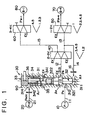
- FIG. 1 schematically shows an oil pressure supplying circuit of the brake B-4 and the brake B-1 within the gear train described above.
- the circuit comprises a hydraulic power source 10, a first hydraulic servo 70, a second hydraulic servo 80, signal pressure generating means 20 (specifically a linear solenoid valve) for generating a signal pressure (accumu-control pressure (P ACC ) in the present embodiment), a pressure governing valve 30 for governing an oil pressure (P S ) from the hydraulic power source 10 with the signal pressure (P ACC ) and a control valve 40, disposed between the pressure governing valve 30 and the first hydraulic servo 70 and the second hydraulic servo 80, for supplying the oil pressure (P S ) from the pressure governing valve 30 selectively to the first hydraulic servo 70 or the second hydraulic servo 80.
- signal pressure generating means 20 specifically a linear solenoid valve
- P S oil pressure
- P S oil pressure
- the pressure governing valve 30 has a first pressure receiving face A 1 to which the signal pressure (P ACC ) from an oil path 21 is applied in one direction (downward in the figure), a second pressure receiving face A 2 to which an oil pressure P B supplied from the pressure governing valve 30 to the control valve 40 is applied in the other direction (upward in the figure) and a third pressure receiving face A 3 to which the oil pressure P B supplied from the control valve 40 to the first hydraulic servo 70 is applied also in the other direction in the present embodiment.
- the first hydraulic servo 70 and the second hydraulic servo 80 correspond to the brake B-4 and the brake B-1 which are frictional engaging elements which engage respectively in different first and second gear shifting steps, i.e. 1ST and 3RD speeds
- the control valve 40 is a gear shift control valve which is changed over between 1ST and 3RD gear shifting steps, i.e. a 2-3 shift valve.
- the hydraulic power source 10 corresponds to an oil pump (not shown) included in the automatic transmission in a strict sense viewed from the oil pressure controller of the whole automatic transmission
- a supply oil path 11 through which a line pressure obtained by governing a discharge pressure of the oil pump by a primary regulator valve is supplied via a manual valve can be considered as the hydraulic power source as far as the control of the two hydraulic servos 70 and 80 are concerned.
- the pressure governing valve 30 comprises a stepped spool 32 having two lands 321 and 322 whose diameters are different and which are slidably fitted into across two diameter sections at the deep inside of a three-stepped hole 31, a main body of the valve, which is created through a valve body 90 of the oil pressure controller and whose diameter is reduced as the depth increases, a plunger 34 disposed similarly at the outside large diameter section, slidably fitted within a hole of a plug 33 and is supported by the large diameter section via the plug 33, a spring 35 disposed between the spool 32 and the plunger 34 and a spring 36 disposed between the plug 33 and the plunger 34.
- a feedback oil chamber 311 is created at the deepest end thereof, an input port 312 is opened at a peripheral groove created at the small diameter section, an output port 313 is opened at a peripheral groove created at the stepped section between the small diameter section and the intermediate diameter section and an exhaust port (EX) is opened at a peripheral groove created at the intermediate diameter section. Further, another exhaust port (EX) is opened at a peripheral groove created at a stepped section between the intermediate diameter section and the large diameter section and an input port 314 is opened at the large diameter section.
- the spool 32 is slidably disposed within the stepped hole 31 as its land 321 having a smaller diameter is fitted into the small diameter section of the stepped hole 31 and its land 322 having a larger diameter is fitted into the intermediate diameter section of the stepped hole 31. It opens/closes the input port 312 with the inner end of the smaller land 321 and opens/closes the drain port (EX) with the inner end of the larger land 322 to govern a pressure.
- the plunger 34 fitted slidably within the hole of the plug 33 is constructed as having a large diameter stopper portion 341 which serves also as a spring seat and a small diameter portion 342 in which a spring housing hole is created.
- the small diameter portion 342 constitutes the pressure receiving face A 1 for receiving the signal pressure (P ACC ).
- a plunger supporting hole of the plug 33 communicates with the signal pressure port 314 via the peripheral groove.
- the output port 313 is connected to the 2-3 shift valve 40 which is the directional control valve of the present invention via an oil path 12.
- the oil path 12 is bifurcated at the 2-3 shift valve 40; one is connected to the first hydraulic servo 70 via a 1-2 shift valve 50 through an oil path 13.and the other is connected to the second hydraulic servo 80 via a 3-4 shift valve 60 through an oil path 15.
- the oil path 13 is bifurcated between the 2-3 shift valve 40 and the 1-2 shift valve 50 and is connected with the feedback oil chamber 311 at the end of the stepped hole 31 via an orifice 16.
- the oil paths within each control valves 40, 50 and 60 assume a relationship of connection shown by solid lines in the figure, except of the oil paths mentioned within the 3-4 shift valve, when the 1ST engine brake is attained.
- a supplied pressure P S is supplied to the hydraulic servo 70 as a brake pressure (P B-4 ) by being governed by the pressure governing valve 30 via the oil path 12, the 2-3 shift valve 40, the oil path 13 and the 1-2 shift valve 50
- the brake pressure P B is applied to the pressure receiving face A 2 of the larger land 322 at the stepped section of the spool 32 as a first feedback pressure and is also applied to the outer edge face of the smaller land 321 as a second feedback pressure coming from the downstream of the 2-3 shift valve 40 via the orifice 16.
- the feedback pressure at this time is applied to a difference of areas of the larger land 322 and the smaller land 321 of the spool 32. Then, a biased force of the spool 32 against the biased force caused by the signal pressure (P ACC ) applied to the outer edge of the plunger 34 and the spring 36 becomes smaller and the displacement of the spool with respect to the change of the signal pressure becomes large.
- the change of the brake pressure (P B-1 ) also becomes large, thereby increasing the pressure governance gain.
- the pressure governing valve 30 can have two modes of control gains of high and low corresponding to the pressure values which the both hydraulic servos require as shown in FIG. 6 in response to the change of the control valve 40 disposed downstream thereof. It is needless to say that the specific values of the control gains may be set by setting dimensions or the like of each element of the pressure governing valve 30. Note that the reason why upper limit values of the brake pressures (P B-4 , P B-1 ) are limited in the figure is because the displacement of the plunger 34 caused by the signal pressure (P ACC ) stops as a stopper at the inner edge of the plunger 34 abuts with the stepped portion of the hole.
- the present embodiment is characterized in that a second feedback oil path 14A from the downstream of the 2-3 shift valve 40 is connected to the intermediate stepped section of the plunger 34 via a feedback port 315. That is, in the present embodiment, the second feedback pressure is applied in the reverse direction differing from the first embodiment.
- the first pressure receiving face A 1 to which the signal pressure is applied in one direction is the outside outer diameter face of the plunger 34
- the second pressure receiving face A 2 to which the oil pressure supplied from the pressure governing valve to the control valve is applied in the other direction is the outer edge face of the land 323 of the spool 32
- the third pressure receiving face A 3 to which the oil pressure supplied from the control valve to the second hydraulic servo is the stepped face of the plunger 34.
- a supplied pressure P S is supplied to the hydraulic servo 70 as a brake pressure (P B-4 ) by being governed by the pressure governing valve 30 via the oil path 12, the 2-3 shift valve 40, the oil path 13 and the 1-2 shift valve 50 and the brake pressure P B is applied to the pressure receiving face A 2 at the outer edge face of the land 323 of the spool 32 as a first feedback pressure via the oil path 12A with the orifice 17.
- each control valves 40, 50 and 60 assume a relationship of connection shown by dotted lines in the figure when the 3RD engine brake is attained.
- the supplied pressure P S is supplied to the hydraulic servo 80 as the brake pressure (P B-1 ) by being governed by the pressure governing valve 30 via the oil path 12, the 2-3 shift valve 40, the oil path 15 and the 3-4 shift valve 60 and is applied also to the third pressure receiving face A 3 formed by the diameter difference portion of the plunger 34 as a second feedback pressure from the port 315 via an oil path 14A.
- two feedback pressure receiving faces A 2 and A 3 are set up in the pressure governing valve 30 and the application and removal of the feedback pressure to one pressure receiving face A 3 among them is made automatically in conjunction with the change of the control valve 40 in the hydraulic circuit in the both embodiments described above, so that it provides an advantage that pressure governing values and gains suited respectively for frictional engaging elements of two brakes (B-1, B-4) which require different engaging pressures may be obtained substantially only by setting the shape of the pressure governing valve, dimensions of each part and spring characteristics.
- the application and removal of the feedback pressure to the pressure receiving face A 3 are made from the oil path 13 or 15 downstream of the 2-3 shift valve 40 which is changed in supplying the oil pressures to the two brakes (B-1, B-4), there is no room to cause an inconsistency between the pressure governing values and gains and the brakes (b-1, B-4) which require them and thereby a fail-safe effect may be obtained.
- the pressure governing valve 30 governs the oil pressure by an oil pressure which is close to the actual oil pressure of the both brakes (B-1, B-4) by applying the feedback pressure to the pressure receiving face A 3 from the oil path 13 or 15, it provides an advantage that the pressure governing accuracy may be improved further.
Landscapes
- Engineering & Computer Science (AREA)
- General Engineering & Computer Science (AREA)
- Physics & Mathematics (AREA)
- Fluid Mechanics (AREA)
- Mechanical Engineering (AREA)
- Control Of Transmission Device (AREA)
Claims (6)
- Régulateur de pression d'huile pour transmission automatique, comprenant :ladite vanne de commande de pression (30) comportant :un premier élément de mise en prise par friction (B-4) pour obtenir un frein moteur dans une vitesse avant ;un deuxième élément de mise en prise par friction (B-1) pour obtenir un frein moteur dans une vitesse avant qui est différente d'une vitesse avant qui met en prise le premier élément de mise en prise par friction ;une source de puissance hydraulique (10) ;un premier servomécanisme hydraulique (70) pour mettre en prise le premier élément de mise en prise par friction(B-4) ;un deuxième servomécanisme hydraulique (80) pour mettre en prise le deuxième élément de mise en prise par friction(B-1) ;un moyen de génération (20) de pression de signal pour générer une pression de signal (PACC) ;une vanne de commande de pression (30) pour commander une pression d'huile (Ps) provenant de ladite source de puissance hydraulique (10) au moyen de ladite pression de signal (PACC) ; etun distributeur (40), placé entre ladite vanne de commande de pression (30) et ledit premier servomécanisme hydraulique (70) et ledit deuxième servomécanisme hydraulique (80), pour fournir sélectivement la pression d'huile (Ps) provenant de ladite vanne de commande de pression (30) audit premier ou deuxième servomécanisme hydraulique (70, 80) ;une première face de réception de pression (A1) à laquelle ladite pression de signal (PACC) est appliquée dans une direction ;une deuxième face de réception de pression (A2) à laquelle la pression d'huile (PB) fournie par ladite vanne de commande de pression (30) audit distributeur (40) est appliquée dans une autre direction ; etune troisième face de réception de pression (A3) à laquelle la pression d'huile (PB) fournie par ledit distributeur (40) audit premier servomécanisme hydraulique (70) est appliquée dans l'autre direction.
- Régulateur de pression d'huile pour transmission automatique selon la revendication 1, dans lequel ladite vanne de commande de pression comprend :un piston sur lequel est créée ladite première face de réception de pression ;une bague placée coaxialement audit piston et sur laquelle sont créées lesdites deuxième et troisième faces de réception de pression ;un premier élément élastique placé entre ledit piston et ladite bague ; etun deuxième élément élastique placé coaxialement du côté opposé par rapport audit premier élément élastique au niveau dudit piston.
- Régulateur de pression d'huile pour transmission automatique selon la revendication 2, dans lequel ladite bague comporte :une première butée sur laquelle est créée ladite deuxième face de réception de pression ; etune deuxième butée dont le diamètre est inférieur à celui de ladite première butée et sur laquelle est créée ladite troisième face de réception de pression.
- Régulateur de pression d'huile pour transmission automatique, comprenant :ladite vanne de commande de pression (30) comportant :un premier élément de mise en prise par friction (B-4) pour obtenir un frein moteur dans une vitesse avant ;un deuxième élément de mise en prise par friction (B-1) pour obtenir un frein moteur dans une vitesse avant qui est différente d'une vitesse avant qui met en prise le premier élément de mise en prise par friction ;une source de puissance hydraulique (10) ;un premier servomécanisme hydraulique (70) pour mettre en prise le premier élément de mise en prise par friction(B-4) ;un deuxième servomécanisme hydraulique (80) pour mettre en prise le deuxième élément de mise en prise par friction(B-1) ;un moyen de génération (20) de pression de signal pour générer une pression de signal (PACC) ;une vanne de commande de pression (30) pour commander une pression d'huile (Ps) provenant de ladite source de puissance hydraulique (10) au moyen de ladite pression de signal (PACC) ; etun distributeur (40), placé entre ladite vanne de commande de pression (30) et ledit premier servomécanisme hydraulique (70) et ledit deuxième servomécanisme hydraulique (80), pour fournir sélectivement la pression d'huile (Ps) provenant de ladite vanne de commande de pression (30) audit premier ou deuxième servomécanisme hydraulique (70, 80) ;une première face de réception de pression (A1) à laquelle ladite pression de signal (PACC) est appliquée dans une direction ;une deuxième face de réception de pression (A2) à laquelle la pression d'huile (PB) fournie par ladite vanne de commande de pression (30) audit distributeur (40) est appliquée dans une autre direction ; etune troisième face de réception de pression (A3) à laquelle la pression d'huile fournie par ledit distributeur (40) audit deuxième servomécanisme hydraulique (80) est appliquée dans une direction.
- Régulateur de pression d'huile pour transmission automatique selon la revendication 4, dans lequel ladite vanne de commande de pression comprend :un piston sur lequel sont créées lesdites première et troisième faces de réception de pression ;une bague placée coaxialement audit piston et sur laquelle est créée ladite deuxième face de réception de pression ;un premier élément élastique placé entre ledit piston et ladite bague ; etun deuxième élément élastique placé coaxialement du côté opposé par rapport audit premier élément élastique au niveau dudit piston.
- Régulateur de pression d'huile selon l'une quelconque des revendications 1 à 5, dans lequel ledit premier servomécanisme hydraulique reçoit la pression d'huile dans une première étape de changement de vitesse et met en prise un élément de mise en prise par friction qui doit être mis en prise dans la première étape de changement de vitesse ;
ledit deuxième servomécanisme hydraulique reçoit la pression d'huile dans une deuxième étape de changement de vitesse qui est différente de la première étape de changement de vitesse et met en prise un élément de mise en prise par friction qui doit être mis en prise dans la deuxième étape de changement de vitesse ; et
ledit distributeur est une vanne de commande de changement de vitesse servant à faire le passage entre ladite première étape de changement de vitesse et ladite deuxième étape de changement de vitesse.
Applications Claiming Priority (3)
| Application Number | Priority Date | Filing Date | Title |
|---|---|---|---|
| JP32949394 | 1994-12-02 | ||
| JP329493/94 | 1994-12-02 | ||
| JP6329493A JP3041211B2 (ja) | 1994-12-02 | 1994-12-02 | 自動変速機の油圧制御装置 |
Publications (3)
| Publication Number | Publication Date |
|---|---|
| EP0715100A2 EP0715100A2 (fr) | 1996-06-05 |
| EP0715100A3 EP0715100A3 (fr) | 1998-04-01 |
| EP0715100B1 true EP0715100B1 (fr) | 2002-10-23 |
Family
ID=18221989
Family Applications (1)
| Application Number | Title | Priority Date | Filing Date |
|---|---|---|---|
| EP95118799A Expired - Lifetime EP0715100B1 (fr) | 1994-12-02 | 1995-11-29 | Régulateur de pression d'huile de transmission automatique |
Country Status (4)
| Country | Link |
|---|---|
| US (1) | US5605516A (fr) |
| EP (1) | EP0715100B1 (fr) |
| JP (1) | JP3041211B2 (fr) |
| DE (1) | DE69528626T2 (fr) |
Families Citing this family (5)
| Publication number | Priority date | Publication date | Assignee | Title |
|---|---|---|---|---|
| JP3414089B2 (ja) * | 1995-12-12 | 2003-06-09 | アイシン・エィ・ダブリュ株式会社 | 自動変速機の油圧制御装置 |
| JP3504097B2 (ja) * | 1996-11-28 | 2004-03-08 | 本田技研工業株式会社 | 車両用自動変速機の油圧制御装置 |
| US6565474B2 (en) * | 2000-03-31 | 2003-05-20 | Aisin Seiki Kabushiki Kaisha | Hydraulic pressure control device for an automatic transmission |
| DE10152959B4 (de) * | 2001-10-26 | 2007-03-15 | Robert Bosch Gmbh | Handwerkzeugmaschine |
| WO2011021421A1 (fr) * | 2009-08-21 | 2011-02-24 | 本田技研工業株式会社 | Dispositif de commande hydraulique |
Family Cites Families (10)
| Publication number | Priority date | Publication date | Assignee | Title |
|---|---|---|---|---|
| JPS4838581B1 (fr) * | 1970-12-27 | 1973-11-19 | ||
| JPS5613221B2 (fr) * | 1972-10-20 | 1981-03-26 | ||
| US4033203A (en) * | 1974-09-17 | 1977-07-05 | Aisin Seiki Kabushiki Kaisha | Hydraulic control system for vehicle transmission means |
| JPS61116158A (ja) * | 1984-11-09 | 1986-06-03 | Honda Motor Co Ltd | 車両用油圧作動式変速機の制御装置 |
| JPS6228555A (ja) * | 1985-07-30 | 1987-02-06 | Nissan Motor Co Ltd | 自動変速機のエンジンブレ−キ制御装置 |
| EP0330409B1 (fr) * | 1988-02-20 | 1995-04-26 | Aisin Aw Co., Ltd. | Dispositif de commande de freinage moteur pour transmission automatique |
| JP3287560B2 (ja) | 1988-03-23 | 2002-06-04 | アイシン・エィ・ダブリュ株式会社 | 自動変速機におけるエンジンブレーキ制御装置 |
| JP2816369B2 (ja) * | 1989-11-15 | 1998-10-27 | アイシン精機株式会社 | 自動変速機の変速制御装置 |
| JPH05156395A (ja) | 1991-12-02 | 1993-06-22 | Mitsubishi Materials Corp | 耐食性に優れた水素吸蔵合金およびその合金からなる二次電池用負電極 |
| JPH06341522A (ja) * | 1993-06-03 | 1994-12-13 | Aisin Aw Co Ltd | 自動変速機の油圧制御装置 |
-
1994
- 1994-12-02 JP JP6329493A patent/JP3041211B2/ja not_active Expired - Fee Related
-
1995
- 1995-11-24 US US08/562,387 patent/US5605516A/en not_active Expired - Lifetime
- 1995-11-29 EP EP95118799A patent/EP0715100B1/fr not_active Expired - Lifetime
- 1995-11-29 DE DE69528626T patent/DE69528626T2/de not_active Expired - Fee Related
Non-Patent Citations (1)
| Title |
|---|
| HOWARD F. TUCKER: "Automatic Transmissions P. 163", 1980, VAN NOSTRAND, NEW-YORK * |
Also Published As
| Publication number | Publication date |
|---|---|
| US5605516A (en) | 1997-02-25 |
| DE69528626T2 (de) | 2003-03-13 |
| DE69528626D1 (de) | 2002-11-28 |
| JP3041211B2 (ja) | 2000-05-15 |
| EP0715100A3 (fr) | 1998-04-01 |
| EP0715100A2 (fr) | 1996-06-05 |
| JPH08159262A (ja) | 1996-06-21 |
Similar Documents
| Publication | Publication Date | Title |
|---|---|---|
| US4513639A (en) | Creeping preventing apparatus in automatic transmission for vehicle | |
| US3881372A (en) | Pressure reducing control device for the hydraulic control circuit of an automatic transmission | |
| GB2037912A (en) | Device for controlling a lock-up clutch in an automatic transmission | |
| US4776240A (en) | Automatic transmission | |
| US4889016A (en) | Hydraulic servo regulating systems in an automatic transmission | |
| US4431096A (en) | Direct-coupling clutch control system for an automatic transmission | |
| US4555964A (en) | Hydraulic control system for automatic transmission with shockless 4-3 shifting as well as shockless 2-3 shifting | |
| US4617841A (en) | Hydraulic control system for automatic transmission with shockless 4-2 shifting | |
| JPH0118311B2 (fr) | ||
| US4607542A (en) | Hydraulic control system for automatic transmission with shockless 4-3 and 4-2 shiftings | |
| US4924731A (en) | Hydraulic control device for an automatic transmission | |
| US5605516A (en) | Oil pressure controller of automatic transmission | |
| JP3478438B2 (ja) | 自動変速機の油圧制御装置 | |
| US5651751A (en) | Shift control system of an automatic transmission used in a vehicle | |
| US5375483A (en) | Directional control valve of a hydraulic control system for automatic transmission | |
| US5626533A (en) | Hydraulic control system of an automatic transmission used in a vehicle | |
| US5518469A (en) | Hydraulic circuit for lock-up device | |
| US5092201A (en) | Hydraulic control device for an automatic transmission | |
| JP2847742B2 (ja) | 自動変速機の制御装置 | |
| JPH0127299B2 (fr) | ||
| JP3516525B2 (ja) | 自動変速機の油圧制御装置 | |
| US4596165A (en) | Direct coupling clutch control system for automatic transmission | |
| KR100299790B1 (ko) | 자동변속기의유압제어시스템 | |
| KR100296267B1 (ko) | 자동변속기의유압제어시스템및변속제어방법 | |
| US4876925A (en) | Hydraulic control system for automatic automotive transmission |
Legal Events
| Date | Code | Title | Description |
|---|---|---|---|
| PUAI | Public reference made under article 153(3) epc to a published international application that has entered the european phase |
Free format text: ORIGINAL CODE: 0009012 |
|
| AK | Designated contracting states |
Kind code of ref document: A2 Designated state(s): DE GB |
|
| PUAL | Search report despatched |
Free format text: ORIGINAL CODE: 0009013 |
|
| AK | Designated contracting states |
Kind code of ref document: A3 Designated state(s): DE GB |
|
| RHK1 | Main classification (correction) |
Ipc: F16H 61/06 |
|
| 17P | Request for examination filed |
Effective date: 19981001 |
|
| 17Q | First examination report despatched |
Effective date: 20000222 |
|
| GRAG | Despatch of communication of intention to grant |
Free format text: ORIGINAL CODE: EPIDOS AGRA |
|
| GRAG | Despatch of communication of intention to grant |
Free format text: ORIGINAL CODE: EPIDOS AGRA |
|
| GRAG | Despatch of communication of intention to grant |
Free format text: ORIGINAL CODE: EPIDOS AGRA |
|
| GRAH | Despatch of communication of intention to grant a patent |
Free format text: ORIGINAL CODE: EPIDOS IGRA |
|
| GRAH | Despatch of communication of intention to grant a patent |
Free format text: ORIGINAL CODE: EPIDOS IGRA |
|
| GRAA | (expected) grant |
Free format text: ORIGINAL CODE: 0009210 |
|
| AK | Designated contracting states |
Kind code of ref document: B1 Designated state(s): DE GB |
|
| REG | Reference to a national code |
Ref country code: GB Ref legal event code: FG4D |
|
| PGFP | Annual fee paid to national office [announced via postgrant information from national office to epo] |
Ref country code: GB Payment date: 20021107 Year of fee payment: 8 |
|
| REF | Corresponds to: |
Ref document number: 69528626 Country of ref document: DE Date of ref document: 20021128 |
|
| PLBE | No opposition filed within time limit |
Free format text: ORIGINAL CODE: 0009261 |
|
| STAA | Information on the status of an ep patent application or granted ep patent |
Free format text: STATUS: NO OPPOSITION FILED WITHIN TIME LIMIT |
|
| 26N | No opposition filed |
Effective date: 20030724 |
|
| PG25 | Lapsed in a contracting state [announced via postgrant information from national office to epo] |
Ref country code: GB Free format text: LAPSE BECAUSE OF NON-PAYMENT OF DUE FEES Effective date: 20031129 |
|
| GBPC | Gb: european patent ceased through non-payment of renewal fee |
Effective date: 20031129 |
|
| PGFP | Annual fee paid to national office [announced via postgrant information from national office to epo] |
Ref country code: DE Payment date: 20081127 Year of fee payment: 14 |
|
| PG25 | Lapsed in a contracting state [announced via postgrant information from national office to epo] |
Ref country code: DE Free format text: LAPSE BECAUSE OF NON-PAYMENT OF DUE FEES Effective date: 20100601 |