EP0715124A2 - Système de contrÔle active des pulsations de pression dynamique dans une chambre de combustion d'une turbine à gaz - Google Patents
Système de contrÔle active des pulsations de pression dynamique dans une chambre de combustion d'une turbine à gaz Download PDFInfo
- Publication number
- EP0715124A2 EP0715124A2 EP95307864A EP95307864A EP0715124A2 EP 0715124 A2 EP0715124 A2 EP 0715124A2 EP 95307864 A EP95307864 A EP 95307864A EP 95307864 A EP95307864 A EP 95307864A EP 0715124 A2 EP0715124 A2 EP 0715124A2
- Authority
- EP
- European Patent Office
- Prior art keywords
- combustor
- valve
- pulse
- frequency
- bleed
- Prior art date
- Legal status (The legal status is an assumption and is not a legal conclusion. Google has not performed a legal analysis and makes no representation as to the accuracy of the status listed.)
- Granted
Links
Images


Classifications
-
- F—MECHANICAL ENGINEERING; LIGHTING; HEATING; WEAPONS; BLASTING
- F23—COMBUSTION APPARATUS; COMBUSTION PROCESSES
- F23R—GENERATING COMBUSTION PRODUCTS OF HIGH PRESSURE OR HIGH VELOCITY, e.g. GAS-TURBINE COMBUSTION CHAMBERS
- F23R3/00—Continuous combustion chambers using liquid or gaseous fuel
- F23R3/02—Continuous combustion chambers using liquid or gaseous fuel characterised by the air-flow or gas-flow configuration
- F23R3/26—Controlling the air flow
-
- F—MECHANICAL ENGINEERING; LIGHTING; HEATING; WEAPONS; BLASTING
- F05—INDEXING SCHEMES RELATING TO ENGINES OR PUMPS IN VARIOUS SUBCLASSES OF CLASSES F01-F04
- F05B—INDEXING SCHEME RELATING TO WIND, SPRING, WEIGHT, INERTIA OR LIKE MOTORS, TO MACHINES OR ENGINES FOR LIQUIDS COVERED BY SUBCLASSES F03B, F03D AND F03G
- F05B2260/00—Function
- F05B2260/96—Preventing, counteracting or reducing vibration or noise
- F05B2260/962—Preventing, counteracting or reducing vibration or noise by means creating "anti-noise"
-
- F—MECHANICAL ENGINEERING; LIGHTING; HEATING; WEAPONS; BLASTING
- F05—INDEXING SCHEMES RELATING TO ENGINES OR PUMPS IN VARIOUS SUBCLASSES OF CLASSES F01-F04
- F05B—INDEXING SCHEME RELATING TO WIND, SPRING, WEIGHT, INERTIA OR LIKE MOTORS, TO MACHINES OR ENGINES FOR LIQUIDS COVERED BY SUBCLASSES F03B, F03D AND F03G
- F05B2270/00—Control
- F05B2270/30—Control parameters, e.g. input parameters
- F05B2270/301—Pressure
-
- F—MECHANICAL ENGINEERING; LIGHTING; HEATING; WEAPONS; BLASTING
- F23—COMBUSTION APPARATUS; COMBUSTION PROCESSES
- F23R—GENERATING COMBUSTION PRODUCTS OF HIGH PRESSURE OR HIGH VELOCITY, e.g. GAS-TURBINE COMBUSTION CHAMBERS
- F23R2900/00—Special features of, or arrangements for continuous combustion chambers; Combustion processes therefor
- F23R2900/00013—Reducing thermo-acoustic vibrations by active means
-
- F—MECHANICAL ENGINEERING; LIGHTING; HEATING; WEAPONS; BLASTING
- F23—COMBUSTION APPARATUS; COMBUSTION PROCESSES
- F23R—GENERATING COMBUSTION PRODUCTS OF HIGH PRESSURE OR HIGH VELOCITY, e.g. GAS-TURBINE COMBUSTION CHAMBERS
- F23R2900/00—Special features of, or arrangements for continuous combustion chambers; Combustion processes therefor
- F23R2900/00014—Reducing thermo-acoustic vibrations by passive means, e.g. by Helmholtz resonators
Definitions
- the present invention relates to the combustor of a gas turbine engine, and, more particularly, to a system for actively controlling dynamic pressure pulses in a gas turbine engine combustor in which a cancellation pulse is produced by periodically extracting air from the combustor to offset a predominant pressure pulse.
- pressure pulses It is well known in the art for pressure pulses to be generated in combustors of gas turbine engines as a consequence of normal functioning, such pressure pulses being dependent on fuel-air stoichiometry, total mass flow, and other factors. Pressure pulses can have adverse effects on an engine, including mechanical and thermal fatigue to combustor hardware. The problem of pressure pulses has been found to be of even greater concern in low emissions combustors since a much higher content of air is introduced to the fuel-air mixers in such designs.
- pressure pulses in the combustor take the form of a circumferential pulse located adjacent to the combustion chamber.
- pressure pulses within the combustor travel not only in a circumferential manner, but also in an axial manner. More specifically, pulses originating in the combustion chamber travel therein and then are reflected back through the fuel-air mixers into the cold section of the combustor. Therefore, the asymmetric compressor discharge pressure bleed has been found to be unsuccessful in effectively combating pressure pulses in the combustor.
- Still another method of counteracting pressure pulses within a gas turbine engine combustor has been the use of detuning tubes positioned at the upstream side of the combustor. These detuning tubes extend into the combustor by a predetermined amount and are effective at balancing out pressure pulses having a fixed amplitude and frequency. Nevertheless, it has been found that pressure pulses within a combustor are dynamic with changing amplitudes and frequencies. Thus, the aforementioned detuning tubes have met with only a moderate degree of success.
- a system for actively controlling pressure pulses in a gas turbine engine combustor includes a means for sensing pressure pulses in the combustor, a first processing means for determining the amplitude and frequency for a predominant pressure pulse of the sensed pressure pulses, a second processing means for calculating an amplitude, a frequency, and a phase angle shift for a cancellation pulse to offset the predominant pressure pulse, and an air bleed means for periodically extracting metered volumes of air from the combustor to produce the cancellation pulse, the air bleed means being controlled by the second processing means.
- the air bleed means includes a bleed manifold in flow communication with the combustor, a first valve in flow communication with the bleed manifold for controlling the amplitude of the cancellation pulse, and a second valve in intermittent flow communication with the first valve to control the frequency and phase angle shift of the cancellation pulse.
- a method of actively controlling dynamic pressure pulses in a gas turbine engine combustor includes the steps of sensing pressure pulses in the combustor, determining an amplitude and a frequency for a predominant pressure pulse of the sensed pressure pulses, calculating an amplitude, a frequency, and a phase angle shift for a cancellation pulse to offset the predominant pressure pulse, and periodically extracting metered volumes of air from the combustor to produce the cancellation pulse.
- This method also involves the steps of variably positioning a first valve to control the amplitude of the cancellation pulse and controlling the intervals in which a second valve is in and out of flow communication with the first valve to control the frequency and phase shift angle of the cancellation pulse.
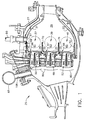
- Fig. 1 depicts a combustion apparatus 25 of the type suitable for use in a gas turbine engine.
- Combustor 25 is a triple annular combustor designed to produce low emissions as described in more detail in U.S. patent 5,323,604, also owned by the assignee of the present invention and hereby incorporated by reference.
- combustor 25 has a hollow body 27 defining a combustion chamber 29 therein.
- Hollow body 27 is generally annular in form and is comprised of an outer liner 31, an inner liner 33, and a domed end or dome 35.
- the present invention is not limited to such an annular configuration and may well be employed with equal effectiveness in a combustion apparatus of the well known cylindrical can or cannular type. Moreover, while the present invention is shown as being utilized in a triple annular combustor, it may also be utilized in a single or double annular design.
- triple annular combustor 25 includes an outer dome 37, a middle dome 39, and an inner dome 41.
- Fuel/air mixers 48, 50 and 52 are provided in openings 43 of middle dome 39, outer dome 37 and inner dome 41, respectively.
- Heat shields 66, 67 and 68 are also provided to segregate the individual primary combustor zones 61, 63 and 65, respectively.
- heat shield 66 includes an annular centerbody 69 to help insulate outer liner 31 from flames burning in primary zone 61.
- Heat shield 67 has annular centerbodies 70 and 71 to segregate primary zone 63 from primary zones 61 and 65, respectively.
- Heat shield 68 has an annular centerbody 72 in order to insulate inner liner 33 from flames burning in primary zone 65.
- System 85 principally involves the extraction of air from combustor 25 in metered amounts which is vented to atmosphere. It will be understood that system 85 is an electro-mechanical system, where the mechanical aspect thereof involves a combustor bleed manifold 87 in flow communication with combustor 25, a combustor bleed valve 89 in flow communication with combustor bleed manifold 87, and a combustor rotating valve 91 which is in intermittent flow communication with combustor bleed valve 89.
- the electrical aspect of system 85 involves the use of a pressure sensor or transducer 93 to sense pressure pulses 80 within combustor 25 and a control unit 95 which determines a predominant pressure pulse from pressure pulses 80 within combustor 25, calculates a cancellation pulse for offsetting the predominant pressure pulse, and controls combustor bleed valve 89 and combustor rotating valve 91 in such manner as to properly extract air from combustor 25 and produce the desired cancellation pulse.
- system 85 first senses pressure pulses 80 in combustion chamber 29.
- pressure transducer 93 preferably is a piezoelectric pressure transducer such as the dynamic pressure sensing system available from Vibrometer of Fribourg, Switzerland. It will be seen in Fig. 2 that pressure transducers 93 are preferably positioned within borescope holes 97 and 99 located along the circumference of combustor 25. Although the intention is to utilize the pre-existing borescope holes 97 and 99, it will be understood that pressure transducers 93 are preferably spaced nearly 180° apart so that pressure pulses 80 may be measured along each side of combustor 25. Signals 100 from pressure transducer 93 indicating the amplitude and respective frequency of pressure pulses 80 are then sent to control unit 95.
- Control unit 95 includes therein a Fast Fourier transformer which preferably scans a predetermined frequency band of interest from signals 100 sent by pressure transducer 93 and then determines the amplitude and frequency of a predominant pressure pulse. It has been found that pressure pulses having a frequency within a range of 100-700 Hertz are a known problem area for combustor 25, but this range may change depending on the design of the combustor.
- the predominant pressure pulse is defined herein as the pressure pulse having the greatest amplitude, although control unit 95 can be programmed to account for other factors in determining the predominant pressure pulse.
- Control unit 95 then takes the amplitude and associated frequency of the predominant pressure pulse and calculates a cancellation pulse to offset it.
- the cancellation pulse will typically have an amplitude and frequency substantially similar to that of the predominant pressure pulse; however, it will be understood that a phase angle shift for the cancellation pulse is also calculated so that the cancellation pulse is substantially 180° out of phase with the predominant pressure pulse.
- Providing a cancellation pulse which offsets only the predominant pressure pulse in combustor 25 has been found to have an effect on other pressure pulses therein and bring the overall amplitude of pressure pulses 80 within an acceptable range (e.g., 2.5 psi delta absolute).
- an acceptable range e.g. 2.5 psi delta absolute
- control unit 95 sends a signal 102 to combustor bleed valve 89 in order to control the amplitude of the cancellation pulse.
- control unit 95 sends a signal 104 to combustor rotating valve 91 in order to control the frequency and phase angle shift of the cancellation pulse.
- combustor bleed manifold 87 is shown as being located upstream of fuel/air mixers 48, 50 and 52 and combustion chamber 29 (see Fig. 1), although combustor bleed manifold 87 could be located downstream of fuel/air mixers 48, 50 and 52 adjacent combustion chamber 29.
- Combustor bleed manifold 87 is currently positioned at the upstream end of combustor 25 in order to take advantage of existing structure for introducing fuel to combustor 25. Nevertheless, positioning combustor bleed manifold 87 on the hot side of combustor 25 could prove to be more desirable since it likely would better offset pressure pulses 80 originating in combustion chamber 29.
- combustor bleed manifold 87 is preferably ring-shaped and includes a plurality of extraction tubes 106 which are connected to combustor bleed manifold 87 at one end and are in flow communication with compressed air entering combustor 25 at the other end.
- the number of extraction tubes 106 is preferably related to the number of staging valves utilized for injecting fuel into combustor 25. It will be understood that compressed air having a generally constant pressure (approximately 100-450 psia) will flow into combustor bleed manifold 87 through extraction tubes 106.
- Combustor bleed valve 89 is in constant flow communication with combustor bleed manifold 87 by means of an air line 108. As stated previously herein, combustor bleed valve 89 is utilized to control the amount or volume of air extracted from combustor 25 and consequently the amplitude of the cancellation pulse. This is accomplished by variably positioning combustor bleed valve 89, preferably by means of an electro-hydraulic servo valve acting as an interface between combustor bleed valve 89 and control unit 95 as known in the gas turbine engine art.
- signal 102 from control unit 95 is input to the servo valve, whereupon the servo valve causes combustor bleed valve 89 to open or close a specified amount to enable the desired volume of air to be extracted.
- Either a linear or rotating variable displacement transformer will preferably be utilized in association with combustor bleed valve 89 in order to transmit back to control unit 95 a signal as to the positioning of combustor bleed valve 89.
- Another portion 110 of air line 108 then extends between combustor bleed valve 89 and combustor rotating valve 91.
- combustor rotating valve 91 The purpose of combustor rotating valve 91 is to control the frequency and phase angle shift of the cancellation pulse.
- combustor rotating valve 91 includes a rotating disk 112 which has a plurality of bleed ports 114 therethrough (see Fig. 4A).
- bleed ports 114 are preferably sized so as to approximate the size of air line 108.
- a seal 111 is provided (see Fig. 3) to prevent air entering combustor rotating valve 91 from spilling out around rotating disk 112 and thus permit the air to flow only through bleed ports 114. Accordingly, as bleed ports 114 align with air line portion 110, the pressurized air transmitted through combustor bleed valve 89 is vented to atmosphere.
- the nature of combustor rotating valve 91 is that there will be times or intervals when no bleed port 114 aligns with air line portion 110, thereby causing flow communication with combustor bleed valve 89 to be intermittent.
- Combustor rotating valve 91 also includes a shaft 116 which is engaged preferably with the middle of rotating disk 112. Shaft 116 is driven by an electric motor 118, which preferably is a stepper motor.
- rotating disk 112 may have a different configuration so long as it provides intermittent flow communication with air line portion 110.
- a rotating disk 112A may have notches 120 about the circumference thereof.
- notches 120 in rotating disk 112A will intermittently align with air line portion 110 so that air is allowed to periodically flow through combustor rotating valve 91.
- pressure pulses 80 within combustor 25 may change due to ambient temperature and air flow changes within combustor 25, as well as transitions involving the lighting of various fuel/air mixers within outer dome 37, middle dome 39, and inner dome 41. Therefore, because pressure pulses 80 are apt to change according to different conditions and factors, system 85 works continuously in a closed loop fashion (see Fig. 5) to update the amplitude and frequency of the predominant pressure pulse. Correspondingly, control unit 95 continuously updates and changes the cancellation pulse as required by changes in the predominant pressure pulse.
Landscapes
- Engineering & Computer Science (AREA)
- Chemical & Material Sciences (AREA)
- Combustion & Propulsion (AREA)
- Mechanical Engineering (AREA)
- General Engineering & Computer Science (AREA)
- Fluidized-Bed Combustion And Resonant Combustion (AREA)
- Measuring Fluid Pressure (AREA)
Applications Claiming Priority (2)
| Application Number | Priority Date | Filing Date | Title |
|---|---|---|---|
| US345081 | 1994-11-28 | ||
| US08/345,081 US5575144A (en) | 1994-11-28 | 1994-11-28 | System and method for actively controlling pressure pulses in a gas turbine engine combustor |
Publications (3)
| Publication Number | Publication Date |
|---|---|
| EP0715124A2 true EP0715124A2 (fr) | 1996-06-05 |
| EP0715124A3 EP0715124A3 (fr) | 1998-12-09 |
| EP0715124B1 EP0715124B1 (fr) | 2002-07-03 |
Family
ID=23353424
Family Applications (1)
| Application Number | Title | Priority Date | Filing Date |
|---|---|---|---|
| EP95307864A Expired - Lifetime EP0715124B1 (fr) | 1994-11-28 | 1995-11-03 | Système de contrôle active des pulsations de pression dynamique dans une chambre de combustion d'une turbine à gaz |
Country Status (4)
| Country | Link |
|---|---|
| US (1) | US5575144A (fr) |
| EP (1) | EP0715124B1 (fr) |
| JP (1) | JPH08284690A (fr) |
| DE (1) | DE69527254T2 (fr) |
Cited By (8)
| Publication number | Priority date | Publication date | Assignee | Title |
|---|---|---|---|---|
| EP0774573A3 (fr) * | 1995-11-14 | 1999-04-14 | United Technologies Corporation | Procédé de minimisation des oxydes d'azote dans une chambre de combustion |
| US6532742B2 (en) | 1999-12-16 | 2003-03-18 | Rolls-Royce Plc | Combustion chamber |
| GB2408806B (en) * | 2003-11-26 | 2008-01-23 | Gen Electric | Method and system for using eddy current transducers in pressure measurements |
| FR2958016A1 (fr) * | 2010-03-23 | 2011-09-30 | Snecma | Methode de reduction des instabilites de combustion par le choix du positionnement d'un prelevement d'air sur une turbomachine |
| EP1632719A3 (fr) * | 2004-09-07 | 2013-07-24 | General Electric Company | Système pour améliorer le rendement thermique d'une chambre de combustion à prémélange pauvre |
| CN104975951A (zh) * | 2014-04-08 | 2015-10-14 | 通用电气公司 | 用于利用燃料加热的间隙控制的方法和设备 |
| US11156164B2 (en) | 2019-05-21 | 2021-10-26 | General Electric Company | System and method for high frequency accoustic dampers with caps |
| US11174792B2 (en) | 2019-05-21 | 2021-11-16 | General Electric Company | System and method for high frequency acoustic dampers with baffles |
Families Citing this family (32)
| Publication number | Priority date | Publication date | Assignee | Title |
|---|---|---|---|---|
| DE19704540C1 (de) * | 1997-02-06 | 1998-07-23 | Siemens Ag | Verfahren zur aktiven Dämpfung einer Verbrennungsschwingung und Verbrennungsvorrichtung |
| US6464489B1 (en) * | 1997-11-24 | 2002-10-15 | Alstom | Method and apparatus for controlling thermoacoustic vibrations in a combustion system |
| WO1999027300A1 (fr) * | 1997-11-26 | 1999-06-03 | Superior Fireplace Company | Regulateur de flammes par ondes |
| EP0926325A3 (fr) | 1997-12-23 | 2001-04-25 | United Technologies Corporation | Dispositif pour une chambre de combustion à combustible liquide |
| US6560967B1 (en) * | 1998-05-29 | 2003-05-13 | Jeffrey Mark Cohen | Method and apparatus for use with a gas fueled combustor |
| US6158957A (en) * | 1998-12-23 | 2000-12-12 | United Technologies Corporation | Thermal barrier removal process |
| US6633828B2 (en) | 2001-03-21 | 2003-10-14 | Honeywell International Inc. | Speed signal variance detection fault system and method |
| JP4056232B2 (ja) | 2001-08-23 | 2008-03-05 | 三菱重工業株式会社 | ガスタービン制御装置、ガスタービンシステム及びガスタービン遠隔監視システム |
| US6879922B2 (en) * | 2001-09-19 | 2005-04-12 | General Electric Company | Systems and methods for suppressing pressure waves using corrective signal |
| US6843061B2 (en) | 2002-02-15 | 2005-01-18 | Siemens Westinghouse Power Corporation | Gas turbine with flexible combustion sensor connection |
| US6742341B2 (en) | 2002-07-16 | 2004-06-01 | Siemens Westinghouse Power Corporation | Automatic combustion control for a gas turbine |
| US6871487B2 (en) * | 2003-02-14 | 2005-03-29 | Kulite Semiconductor Products, Inc. | System for detecting and compensating for aerodynamic instabilities in turbo-jet engines |
| US6976351B2 (en) * | 2003-04-04 | 2005-12-20 | General Electric Company | Methods and apparatus for monitoring gas turbine combustion dynamics |
| US7278266B2 (en) * | 2004-08-31 | 2007-10-09 | General Electric Company | Methods and apparatus for gas turbine engine lean blowout avoidance |
| US7159401B1 (en) * | 2004-12-23 | 2007-01-09 | Kulite Semiconductor Products, Inc. | System for detecting and compensating for aerodynamic instabilities in turbo-jet engines |
| US7406820B2 (en) * | 2005-03-25 | 2008-08-05 | Honeywell International Inc. | System and method for turbine engine adaptive control for mitigation of instabilities |
| US8083494B2 (en) * | 2005-07-05 | 2011-12-27 | Gestion Serge Benjamin Inc. | Pulse jet engine having an acoustically enhanced ejector system |
| US7654092B2 (en) | 2006-07-18 | 2010-02-02 | Siemens Energy, Inc. | System for modulating fuel supply to individual fuel nozzles in a can-annular gas turbine |
| US20090077945A1 (en) * | 2007-08-24 | 2009-03-26 | Delavan Inc | Variable amplitude double binary valve system for active fuel control |
| GB0823085D0 (en) * | 2008-12-19 | 2009-01-28 | Rolls Royce Plc | Combustor Rumble |
| US8567197B2 (en) | 2008-12-31 | 2013-10-29 | General Electric Company | Acoustic damper |
| US10119468B2 (en) * | 2012-02-06 | 2018-11-06 | United Technologies Corporation | Customer bleed air pressure loss reduction |
| US9709279B2 (en) | 2014-02-27 | 2017-07-18 | General Electric Company | System and method for control of combustion dynamics in combustion system |
| US9709278B2 (en) | 2014-03-12 | 2017-07-18 | General Electric Company | System and method for control of combustion dynamics in combustion system |
| US9644846B2 (en) * | 2014-04-08 | 2017-05-09 | General Electric Company | Systems and methods for control of combustion dynamics and modal coupling in gas turbine engine |
| US9845956B2 (en) | 2014-04-09 | 2017-12-19 | General Electric Company | System and method for control of combustion dynamics in combustion system |
| US9845732B2 (en) | 2014-05-28 | 2017-12-19 | General Electric Company | Systems and methods for variation of injectors for coherence reduction in combustion system |
| US10113747B2 (en) | 2015-04-15 | 2018-10-30 | General Electric Company | Systems and methods for control of combustion dynamics in combustion system |
| US10670271B2 (en) | 2016-09-30 | 2020-06-02 | DOOSAN Heavy Industries Construction Co., LTD | Acoustic dampening liner cap and gas turbine combustor including the same |
| US11092083B2 (en) * | 2017-02-10 | 2021-08-17 | General Electric Company | Pressure sensor assembly for a turbine engine |
| CN109140493B (zh) * | 2018-08-28 | 2019-11-29 | 苏州工业园区蓝天燃气热电有限公司 | 一种降低燃烧脉动与排放污染的ge燃机燃烧调整的方法 |
| CN109162814B (zh) * | 2018-09-03 | 2019-11-26 | 华电电力科学研究院有限公司 | 一种dln-2.6燃烧系统燃烧调整方法 |
Citations (1)
| Publication number | Priority date | Publication date | Assignee | Title |
|---|---|---|---|---|
| US5323604A (en) | 1992-11-16 | 1994-06-28 | General Electric Company | Triple annular combustor for gas turbine engine |
Family Cites Families (10)
| Publication number | Priority date | Publication date | Assignee | Title |
|---|---|---|---|---|
| US3936606A (en) * | 1971-12-07 | 1976-02-03 | Wanke Ronald L | Acoustic abatement method and apparatus |
| US4199936A (en) * | 1975-12-24 | 1980-04-29 | The Boeing Company | Gas turbine engine combustion noise suppressor |
| FR2370171A1 (fr) * | 1976-11-05 | 1978-06-02 | Snecma | Procede et dispositif pour la diminution du bruit des turbomachines |
| FR2370170A1 (fr) * | 1976-11-05 | 1978-06-02 | Snecma | Procede et dispositif pour la diminution du bruit des turbomachines |
| GB8329218D0 (en) * | 1983-11-02 | 1983-12-07 | Ffowcs Williams J E | Reheat combustion system for gas turbine engine |
| US5082421A (en) * | 1986-04-28 | 1992-01-21 | Rolls-Royce Plc | Active control of unsteady motion phenomena in turbomachinery |
| FR2645247B2 (fr) * | 1988-06-22 | 1991-06-07 | Centre Nat Rech Scient | Procede et dispositif de controle actif des instabilites de combustion |
| US5197280A (en) * | 1989-03-20 | 1993-03-30 | General Electric Company | Control system and method for controlling a gas turbine engine |
| US5347586A (en) * | 1992-04-28 | 1994-09-13 | Westinghouse Electric Corporation | Adaptive system for controlling noise generated by or emanating from a primary noise source |
| US5386689A (en) * | 1992-10-13 | 1995-02-07 | Noises Off, Inc. | Active gas turbine (jet) engine noise suppression |
-
1994
- 1994-11-28 US US08/345,081 patent/US5575144A/en not_active Expired - Fee Related
-
1995
- 1995-11-03 EP EP95307864A patent/EP0715124B1/fr not_active Expired - Lifetime
- 1995-11-03 DE DE69527254T patent/DE69527254T2/de not_active Expired - Fee Related
- 1995-11-24 JP JP7305295A patent/JPH08284690A/ja not_active Withdrawn
Patent Citations (1)
| Publication number | Priority date | Publication date | Assignee | Title |
|---|---|---|---|---|
| US5323604A (en) | 1992-11-16 | 1994-06-28 | General Electric Company | Triple annular combustor for gas turbine engine |
Cited By (9)
| Publication number | Priority date | Publication date | Assignee | Title |
|---|---|---|---|---|
| EP0774573A3 (fr) * | 1995-11-14 | 1999-04-14 | United Technologies Corporation | Procédé de minimisation des oxydes d'azote dans une chambre de combustion |
| US6532742B2 (en) | 1999-12-16 | 2003-03-18 | Rolls-Royce Plc | Combustion chamber |
| GB2408806B (en) * | 2003-11-26 | 2008-01-23 | Gen Electric | Method and system for using eddy current transducers in pressure measurements |
| EP1632719A3 (fr) * | 2004-09-07 | 2013-07-24 | General Electric Company | Système pour améliorer le rendement thermique d'une chambre de combustion à prémélange pauvre |
| FR2958016A1 (fr) * | 2010-03-23 | 2011-09-30 | Snecma | Methode de reduction des instabilites de combustion par le choix du positionnement d'un prelevement d'air sur une turbomachine |
| CN104975951A (zh) * | 2014-04-08 | 2015-10-14 | 通用电气公司 | 用于利用燃料加热的间隙控制的方法和设备 |
| US9963994B2 (en) | 2014-04-08 | 2018-05-08 | General Electric Company | Method and apparatus for clearance control utilizing fuel heating |
| US11156164B2 (en) | 2019-05-21 | 2021-10-26 | General Electric Company | System and method for high frequency accoustic dampers with caps |
| US11174792B2 (en) | 2019-05-21 | 2021-11-16 | General Electric Company | System and method for high frequency acoustic dampers with baffles |
Also Published As
| Publication number | Publication date |
|---|---|
| US5575144A (en) | 1996-11-19 |
| EP0715124B1 (fr) | 2002-07-03 |
| JPH08284690A (ja) | 1996-10-29 |
| DE69527254T2 (de) | 2003-03-27 |
| EP0715124A3 (fr) | 1998-12-09 |
| DE69527254D1 (de) | 2002-08-08 |
Similar Documents
| Publication | Publication Date | Title |
|---|---|---|
| US5575144A (en) | System and method for actively controlling pressure pulses in a gas turbine engine combustor | |
| US7775052B2 (en) | Active combustion control system for gas turbine engines | |
| US8024934B2 (en) | System and method for attenuating combustion oscillations in a gas turbine engine | |
| US8417434B2 (en) | Active pattern factor control for gas turbine engines | |
| US6634457B2 (en) | Apparatus for damping acoustic vibrations in a combustor | |
| EP2486328B1 (fr) | Appareil à combustion | |
| CA2748256C (fr) | Amortisseur acoustique | |
| EP2494156B1 (fr) | Procédé de démarrage d'une turbine à gaz | |
| US20190017441A1 (en) | Gas turbine engine combustor | |
| US20040248053A1 (en) | Damping arrangement for reducing combustion-chamber pulsation in a gas turbine system | |
| JPH01208616A (ja) | 燃焼室ライナインサート | |
| EP3372818A1 (fr) | Amortisseur de vibrations à déplacement variable pour un moteur à double flux | |
| WO1981001171A1 (fr) | Procede evitant une combustion anormale dans un moteur a combustion interne et dispositif de mise en application du procede | |
| JP2005344716A (ja) | 燃焼器火炎温度を推定する方法 | |
| EP3255346B1 (fr) | Réduction du bruit provenant de la chambre de combustion d'un moteur à turbine à gaz | |
| EP1566524B1 (fr) | Refroidissement d'un carter de turbine | |
| EP3309373B1 (fr) | Démarreur intégré pour véhicule aérien | |
| EP3309374A1 (fr) | Détection de problème de démarreur | |
| EP3044439B1 (fr) | Refroidissement des bords pour des panneaux de chambre de combustion | |
| CA1076838A (fr) | Instrument et methode de mesure pour les pressions | |
| EP4028694B1 (fr) | Système pour amortisseurs acoustiques à volumes multiples dans un panneau avant de chambre de combustion | |
| WO1995001501A1 (fr) | Programme de mise en marche des regimes de pression de carburant dans une turbine a gaz | |
| US20230194090A1 (en) | Combustor with resonator | |
| US20190063314A1 (en) | Active system generating destructive acoustic interference for an aircraft engine with multiple fan spools | |
| US10180108B2 (en) | System and method for operating a gas turbine |
Legal Events
| Date | Code | Title | Description |
|---|---|---|---|
| PUAI | Public reference made under article 153(3) epc to a published international application that has entered the european phase |
Free format text: ORIGINAL CODE: 0009012 |
|
| AK | Designated contracting states |
Kind code of ref document: A2 Designated state(s): DE FR GB |
|
| PUAL | Search report despatched |
Free format text: ORIGINAL CODE: 0009013 |
|
| AK | Designated contracting states |
Kind code of ref document: A3 Designated state(s): DE FR GB |
|
| 17P | Request for examination filed |
Effective date: 19990609 |
|
| GRAG | Despatch of communication of intention to grant |
Free format text: ORIGINAL CODE: EPIDOS AGRA |
|
| 17Q | First examination report despatched |
Effective date: 20011112 |
|
| GRAG | Despatch of communication of intention to grant |
Free format text: ORIGINAL CODE: EPIDOS AGRA |
|
| GRAH | Despatch of communication of intention to grant a patent |
Free format text: ORIGINAL CODE: EPIDOS IGRA |
|
| GRAG | Despatch of communication of intention to grant |
Free format text: ORIGINAL CODE: EPIDOS AGRA |
|
| GRAH | Despatch of communication of intention to grant a patent |
Free format text: ORIGINAL CODE: EPIDOS IGRA |
|
| GRAH | Despatch of communication of intention to grant a patent |
Free format text: ORIGINAL CODE: EPIDOS IGRA |
|
| GRAA | (expected) grant |
Free format text: ORIGINAL CODE: 0009210 |
|
| AK | Designated contracting states |
Kind code of ref document: B1 Designated state(s): DE FR GB |
|
| REF | Corresponds to: |
Ref document number: 69527254 Country of ref document: DE Date of ref document: 20020808 |
|
| ET | Fr: translation filed | ||
| PLBE | No opposition filed within time limit |
Free format text: ORIGINAL CODE: 0009261 |
|
| STAA | Information on the status of an ep patent application or granted ep patent |
Free format text: STATUS: NO OPPOSITION FILED WITHIN TIME LIMIT |
|
| 26N | No opposition filed |
Effective date: 20030404 |
|
| PGFP | Annual fee paid to national office [announced via postgrant information from national office to epo] |
Ref country code: GB Payment date: 20031029 Year of fee payment: 9 |
|
| PGFP | Annual fee paid to national office [announced via postgrant information from national office to epo] |
Ref country code: FR Payment date: 20031119 Year of fee payment: 9 |
|
| PGFP | Annual fee paid to national office [announced via postgrant information from national office to epo] |
Ref country code: DE Payment date: 20031231 Year of fee payment: 9 |
|
| PG25 | Lapsed in a contracting state [announced via postgrant information from national office to epo] |
Ref country code: GB Free format text: LAPSE BECAUSE OF NON-PAYMENT OF DUE FEES Effective date: 20041103 |
|
| PG25 | Lapsed in a contracting state [announced via postgrant information from national office to epo] |
Ref country code: DE Free format text: LAPSE BECAUSE OF NON-PAYMENT OF DUE FEES Effective date: 20050601 |
|
| GBPC | Gb: european patent ceased through non-payment of renewal fee |
Effective date: 20041103 |
|
| PG25 | Lapsed in a contracting state [announced via postgrant information from national office to epo] |
Ref country code: FR Free format text: LAPSE BECAUSE OF NON-PAYMENT OF DUE FEES Effective date: 20050729 |
|
| REG | Reference to a national code |
Ref country code: FR Ref legal event code: ST |