EP0715188A2 - Dispositif de mesure de puits et procédé avec compensation du puits - Google Patents
Dispositif de mesure de puits et procédé avec compensation du puits Download PDFInfo
- Publication number
- EP0715188A2 EP0715188A2 EP95308570A EP95308570A EP0715188A2 EP 0715188 A2 EP0715188 A2 EP 0715188A2 EP 95308570 A EP95308570 A EP 95308570A EP 95308570 A EP95308570 A EP 95308570A EP 0715188 A2 EP0715188 A2 EP 0715188A2
- Authority
- EP
- European Patent Office
- Prior art keywords
- electromagnetic energy
- antennas
- transmitting antennas
- phase shift
- transmitting
- Prior art date
- Legal status (The legal status is an assumption and is not a legal conclusion. Google has not performed a legal analysis and makes no representation as to the accuracy of the status listed.)
- Granted
Links
Images


Classifications
-
- G—PHYSICS
- G01—MEASURING; TESTING
- G01V—GEOPHYSICS; GRAVITATIONAL MEASUREMENTS; DETECTING MASSES OR OBJECTS; TAGS
- G01V3/00—Electric or magnetic prospecting or detecting; Measuring magnetic field characteristics of the earth, e.g. declination, deviation
- G01V3/18—Electric or magnetic prospecting or detecting; Measuring magnetic field characteristics of the earth, e.g. declination, deviation specially adapted for well-logging
- G01V3/30—Electric or magnetic prospecting or detecting; Measuring magnetic field characteristics of the earth, e.g. declination, deviation specially adapted for well-logging operating with electromagnetic waves
Definitions
- This invention relates to the field of well logging and, more particularly, to well logging techniques and apparatus for determining formation properties, such as resistivity, at several different radial depths of investigation and with compensation for factors such as borehole rugosity and drift of electronic components.
- the invention has general application in the well logging art, but is particularly useful in measuring while drilling.
- a commonly used technique for evaluating formations surrounding an earth borehole is resistivity logging.
- Porous formations having high resistivity generally indicate the presence of hydrocarbons, while porous formations with low resistivity are generally water saturated.
- the region immediately surrounding the borehole can be invaded by borehole fluid or mud filtrate and have a different resistivity than the virgin formation. If a resistivity logging device has only one radial depth of investigation, there is limited ability to measure resistivity of all zones of interest, and there may be difficulty in determining if the measured resistivity represents the invaded zone, the virgin zone, or some combination of the two zones. However, if the resistivity logging device has multiple radial depths of investigation, there is greater flexibility.
- the combination of the two can provide additional information such as the extent of invasion. It is also possible to combine two or more measurements, for example a shallow measurement and a deeper measurement, to compute a better estimate of the true formation resistivity.
- Wireline resistivity logging tools have long been provided with two or more radial depths of investigation.
- Conventional wireline resistivity logging tools typically achieve two depths of investigation by using a short and a long vertical array of electrodes or coils.
- a long vertical array provides a greater radial depth of investigation than does a short vertical array.
- measuring while drilling tools have been provided with multiple radial depths of investigation.
- a type of well logging which is of interest herein is so-called electromagnetic propagation logging, which can be used to measure the resistivity of the formation surrounding a borehole.
- electromagnetic propagation logging which can be used to measure the resistivity of the formation surrounding a borehole.
- U.S. Patent No. 3,551,797 describes a technique wherein electromagnetic energy is transmitted into the formation, and energy which returns to the borehole is measured at a receiver pair to determine the attenuation and/or the phase shift of the electromagnetic energy propagating in the formation. More than one vertical spacing between a transmitter and different receiver pairs may be used to obtain different radial depths of investigation.
- a receiver pair relatively close to the transmitter can be used to obtain attenuation and/or phase shift information from which the properties of the invaded zone are determined, and measurements of the attenuation and/or phase shift from a receiver pair relatively far from the transmitter can be used to obtain the properties of the deeper uninvaded formations.
- Either attenuation or phase shift can be used to determine a bulk value of the electromagnetic skin depth for the formation, with the bulk conductivity then being determinable from the electromagnetic skin depth.
- U.S. Patent No. 4,899,112 there is disclosed a logging apparatus for determining resistivity of formations at two different radial depths of investigation using signals received at only a single receiver pair.
- the resistivity of formations at a relatively shallow depth of investigation around the receiver pair is determined as a function of the phase shift measured at the receiver pair, and the resistivity of formations at a relatively deep depth of investigation around the receiver pair is determined as a function of the attenuation measured at the receiver pair.
- the apparatus is particularly advantageous for measurement while-drilling, where it is desirable to obtain resistivity at multiple depths of investigation while minimizing the length and complexity of the logging device.
- 4,899,112 also discloses a so-called borehole compensated embodiment, where the receiver pair is located between and equally spaced from, a pair of transmitting antennas that can be alternately energized.
- the signals received at the receiver pair can be averaged to obtain borehole compensated signals; i.e., signals from which (1) drift of electronic components, and (2) borehole rugosity, have been reduced or removed by cancellation.
- One or more additional transmitters can be added to the logging device just described, at different spacing(s), to attain further depths of investigation. However, in order to provide borehole compensation for each additional spacing, it would be necessary to provide two transmitters (one on each side of the receivers) for each such additional spacing.
- the apparatus and technique of the present invention provides advantages of borehole compensation without the requirement of having, for each transmitter to receiver pair spacing, an "equal and opposite" transmitter with the same spacing on the other side of the receiver pair.
- two transmitting antennas at equal and opposite spacing from the midpoint of the receiving antenna pair, and a third transmitting antenna at a different spacing from the midpoint of the receiving antenna pair, without the need for providing a fourth transmitting antenna to obtain the benefits of borehole compensation.
- At least three transmitting antennas are provided, with at least one of them on one side of the receiving antenna pair and at least two of them on the other side of the receiving antenna pair.
- none of the spacings between respective transmitting antennas and the midpoint of the receiving antenna pair are the same, the spacings preferably differing by at least one inch.
- an apparatus for determining a property, such as resistivity, of earth formations surrounding a borehole that comprises: an elongated logging device movable through the borehole; first, third, and second transmitting antennas longitudinally spaced on the device; a pair of longitudinally spaced receiving antennas on the device, the pair of receiving antennas being located between the second transmitting antenna and one of the first and third transmitting antennas; the first, third, and second transmitting antennas being spaced from the midpoint between the receiver pair by first, third, and second distances, respectively, and the first and second distances being substantially the same; means for energizing the first, third, and second transmitting antennas with electromagnetic energy; means for receiving, at the pair of receiving antennas, electromagnetic energy from the transmitting antennas; means for determining, from electromagnetic energy received at the pair of receiving antennas, first, third, and second phase shift and/or attenuation measurements of electromagnetic energy transmitted from the first, third, and
- the third distance is smaller than the second distance, and in another embodiment of this form of the invention, the third distance is greater than said second distance.
- formation resistivity is determined at four borehole compensated depths of investigation.
- the first, third, and second transmitting antennas are spaced from the midpoint between the receiving antenna pair by first, third, and second distances, respectively, said first, third, and second distances being different.
- the means for determining resistivity includes means for combining at least one weighted measurement of phase shift and/or attenuation of electromagnetic energy from the first or third transmitting antenna, and a weighted measurement of phase shift and/or attenuation of electromagnetic energy from the second transmitting antenna.
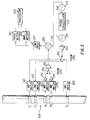
- Figure 1 is a schematic diagram, partially in block form, of a system in accordance with an embodiment of the invention.
- Figure 2 is a schematic diagram, partially in block form, of an embodiment of the electronics of the Fig. 1 embodiment.
- Figure 3 illustrates a variation of the Figure 2 embodiment.
- Figure 4 which includes Figures 4A and 4B placed one below another, is a flow diagram of a routine for controlling a processor in practicing the embodiment of Figure 2 or 3.
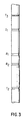
- Figure 5 illustrates a logging device with five transmitting antennas in accordance with a further embodiment of the invention.
- Figure 6 is a diagram which illustrates the placement of antennas in accordance with a further embodiment of the invention.
- Figure 7 illustrates another logging device with three transmitters in accordance with a further embodiment of the invention.
- Figure 8 which includes Figures 8A and 8B placed one below another, is a flow diagram of a routine for controlling a processor in accordance with a further embodiment of the invention.
- FIG. 1 there is illustrated an embodiment of the invention in the form of a logging-while-drilling apparatus and method.
- a platform and derrick 10 are positioned over a borehole 11 that is formed in the earth by rotary drilling.
- a drill string 12 is suspended within the borehole and includes a drill bit 15 at its lower end.
- the drill string 12, and the drill bit 15 attached thereto, is rotated by a rotating table 16 (energized by means not shown) which engages a kelly 17 at the upper end of the drill string.
- the drill string is suspended from a hook 18 attached to a travelling block (not shown).
- the kelly is connected to the hook through a rotary swivel 19 which permits rotation of the drill string relative to the hook.
- Drilling fluid or mud 26 is contained in a pit 27 in the earth.
- a pump 29 pumps the drilling fluid into the drill string 12 via a port in the swivel 19 to flow downward through the center of drill string 12.
- the drilling fluid exits the drill string via ports in the drill bit 15 and then circulates upward in the region between the outside of the drill string and the periphery of the borehole.
- the drilling fluid thereby carries formation cuttings to the surface of the earth, and the drilling fluid is returned to the pit 27 for recirculation.
- the small arrows in the Figure illustrate the typical direction of flow of the drilling fluid.
- Subsystem 100 includes a measuring apparatus 200 which includes at least three transmitting antennas T1, T2, and T3, and receiving antennas R1 and R2, and operates in the manner to be described below.
- the antennas can be of the type described in the referenced U.S. Patent 4,899,112; that is coils wound on mounting material around a special section of metal drill collar which comprises part of the subsystem 100.
- a communications transmitting portion of the downhole subsystem includes an acoustic transmitter 56, which generates an acoustic signal in the drilling fluid that is representative of the measured downhole conditions.
- acoustic transmitter employs a device known as a "mud siren" which includes a slotted stator and a slotted rotor that rotates and repeatedly interrupts the flow of drilling fluid to establish a desired acoustic wave signal in the drilling fluid.
- the generated acoustic mud wave travels upward in the fluid through the center of the drill string at the speed of sound in the fluid.
- the acoustic wave is received at the surface of the earth by transducers represented by reference numeral 31.
- the transducers which are, for example, piezoelectric transducers, convert the received acoustic signals to electronic signals.
- the output of the transducers 31 is coupled to the uphole receiver subsystem 90 which is operative to demodulate the transmitted signals, which are then coupled to processor 85 and recorder 45.
- Transmitter 56 is controlled by transmitter control and driving electronics 57 which includes analog-to-digital (A/D) circuitry that converts the signals representative of downhole conditions into digital form.
- the control and driving electronics 57 may also include a suitable modulator, such as a phase shift keying (PSK) modulator, which conventionally produces driving signals for application to the transmitter 56.
- PSK phase shift keying
- These driving signals can be used to apply appropriate modulation to the mud siren of transmitter 56. It will be understood that alternative techniques can be employed for communicating logging information to the surface of the earth.
- the downhole subsystem 100 further includes acquisition and processor electronics 58. These electronics include a microprocessor (with associated memory, clock circuitry, and interface circuitry), and processing circuitry.
- the acquisition and processor electronics 58 are coupled to the measuring apparatus 200 and obtain measurement information therefrom.
- the acquisition and processor electronics is capable of storing data from the measuring apparatus, processing the data and storing the results, and coupling any desired portion of the information it contains to the transmitter control and driving electronics 57 for transmission to the surface by transmitter 56.
- a battery 53 may provide downhole power.
- a downhole generator (not shown) such as a so-called "mud turbine” powered by the drilling fluid, can also be utilized to provide power during drilling.
- Fig. 2 is a block diagram of electronics in the measuring apparatus 200 and the acquisition and processor electronics 58.
- An oscillator 211 produces an electrical signal of frequency f [e.g. at 2 MHz], which is amplified by amplifier 212 and applied, via electronically controlled switch 275, to one of the transmitting antennas T1, T2 or T3, through respective impedance matching circuits 221, 222 and 223.
- the switch 275 under control of the processor 270, selects the transmitter T1, T2, or T3 that is to be energized.
- the signal from receiver R1 is coupled, via impedance matching circuit 230 and preamplifier 231, to one input of an electronically controlled switch 250.
- the signal from receiver R2 is coupled via impedance matching circuit 240 and preamplifier 241 to the other input of the switch 250.
- the switch 250 under control of processor 270, selects the (R1) or (R2) receiver output.
- the selected signal is amplified by amplifier 251 and subsequently translated to a lower frequency f using a known heterodyne technique.
- a local oscillator 213 is in a phase locked loop (represented at 215) with the master oscillator 211.
- the local oscillator 213 has a frequency f + f, where f is typically a few kilohertz or less.
- a signal from the local oscillator is mixed with the received signal by a mixer 255, and the mixer output is passed through a low pass filter 257 which blocks signals at f and f + f and passes the signal at f.
- the signal at frequency f contains the phase and amplitude information of the original signal at frequency f.
- the recognized advantage of this frequency translation is that it is easier to measure the phase and amplitude at kilohertz or lower frequencies than at megahertz frequencies.
- the signal at frequency f is measured with a phase meter 261 and with an amplitude meter 262, and the results are input to the processor 270.
- the phase meter 261 may utilize a reference signal from the phase locked loop 215.
- the phase and amplitude meters may also include sample-and-hold circuits, to implement comparison of the signal from the respective receivers.
- the processor may compute the relative phase and amplitude from the measurements it receives.
- the processor 270 has associated memory clocking, and interface circuitry (not shown), as is conventional.
- the processor implements storage of the measurements of phase and amplitude, processing of these measurements in the manner to be described, storage of the results of the processing, and/or coupling of the measurements and/or processing results to the control and driving electronics for transmission to the earth's surface.
- a downhole clock is utilized to keep track of time, which can subsequently be correlated with depth level by virtue of keeping a record of the drill string progress.
- the clock which can typically be part of the system in conjunction with the processor 270, can be synchronized with the system before a trip downhole.
- communication with the downhole subsystem using mud pulse technology or other suitable communication means, can be utilized to convey timing synchronization and/or depth level information, as well as to communicate data in general. It will be understood that the invention can be utilized in conjunction with any suitable technique for keeping track of depth level.
- the Fig. 2 circuit is like that of the borehole compensated embodiment of U.S. Patent 4,899,112.
- U.S. Patent 4,899,112 describes in detail how resistivity at a relatively deep depth of investigation is obtained from attenuation measured at the receiver pair, and how resistivity at a relatively shallow depth of investigation is obtained from phase shift measured at the receiver pair.
- a table look-up can be used for this purpose, and reference can be made to said U.S. Patent 4,899,112 for further detail.
- a downward propagating wave has a phase P 1D and an amplitude A 1D at the location of receiver R1 and a phase P 2D and an amplitude A 2D at the location of receiver R2.
- P 1D , P 2D , A 1D , and A 2D are the phases and amplitudes as measured by an ideal circuit with no phase shift, gain, or offset errors.
- the rest of the electronics chain switch 250, amplifier 251, mixer 255, low pass filter 257, phase meter 261, amplitude meter 262, and processor 270) are common to signals from R1 and R2, and do not introduce phase or amplitude differences.
- the inaccuracies which occur in uncompensated measurements are eliminated in the referenced U.S. Patent 4,899,112 with borehole compensation, which is obtained using the second transmitter T2.
- the upward propagating wave has phase P 1U and amplitude A 1U at the location of receiver R1 and a phase P 2U and an amplitude A 2U at the location of receiver R2.
- the transmitter T3 is utilized to obtain two further depths of investigation, and the measurements thereof are borehole compensated, without the need for providing an "equal and opposite" transmitter; i.e., a corresponding transmitter at the same spacing from the receivers as T3, but on the other side of the receivers.
- Error signals are derived from the measurement obtained using T1 and T2, and are used to correct (or compensate) measurements made with transmitter T3.
- PS' and AT' will generally differ from PS and AT. However, the phase shift and attenuation errors introduced by differences between the receivers and the receiver electronics will be unchanged.
- This technique reduces the complexity and cost of adding additional depths of investigation to the logging tool, while retaining the advantages of borehole compensation.
- Significant further advantage is obtained for the situation when T3 is placed above T1, as shown in Figure 3. [Processing will be the same as just described.] In this case, the tool length must only be increased by approximately the distance between T1 and T3. In a conventionally borehole compensated long array, the tool length would have to be increased by twice such distance. It will be understood that further transmitters can be added, consistent with the principles set forth.
- FIG. 4 there is shown a flow diagram of a routine for controlling the processor 270 in accordance with an embodiment of the invention for obtaining borehole compensated resistivity from attenuation and borehole compensated resistivity from phase shift for the spacing of transmitters (T1, T2), and also for the spacing of transmitter T3.
- the block 410 represents initializing of a transmitter index to the first transmitter (T1).
- the transmitter is activated, and the relative phase shift and attenuation are measured and stored, as represented by the block 412. Inquiry is then made (decision block 415) as to whether the last transmitter index has been reached.
- the transmitter index is incremented (block 417), block 412 is re-entered, and the loop 419 is continued until measurements have been made and stored for each of the three transmitters (T1, T2, and T3, for the present embodiment).
- the block 425 is then entered, and, for the T1, T2 spacing, borehole compensated phase shift [PS BHC ] and attenuation [AT BHC ] are computed using equation (5) and equation (6). These measured values can then be used to determine and store (block 427) the resistivity from attenuation [R AT ] and the resistivity from phase shift [R ⁇ ] at the spacing of T1, T2. This determination can be made, for example, in accordance with the teachings of U.S. Patent No.
- the same type of table look-up technique can then be used (block 440) to determine and store the resistivity from attenuation [R' AT ] and the resistivity from phase shift [R' ⁇ ] at the T3 spacing.
- resistivity can be determined, with borehole compensation, at four effective depths of investigation [namely, R AT for the T1, T2 spacing, R ⁇ for the T1, T2 spacing, R' AT for the T3 spacing, and R' ⁇ for the T3 spacing].
- the block 410 can then be re-entered for processing at further depth levels.
- FIG. 5 there is shown a further embodiment of the invention, which may be employed, for example, as the logging device 200 of the measuring while drilling equipment illustrated in Figure 1.
- the embodiment of Figure 5 has a receiver pair comprising receiving antennas R1, R2, and five transmitting antennas, T1, T2, T3, T4, and T5.
- the transmitting antennas T1, T3, and T5 are above the receiver antennas, and the transmitting antennas T2 and T4 are below the receiving antennas.
- the spacings of the transmitting antennas, with respect to the midpoint of the receiving antennas, (0), are all different.
- the spacing between receiving antennas R1 and R2 may be 6 inches, and the spacing from the receiver midpoint to each transmitter T1 through T5 may be 10 inches, 16 inches, 22 inches, 28 inches, and 34 inches, respectively.
- Each transmitter can be individually energized (for example, on a time multiplexed or a frequency multiplexed basis), and a relative phase shift measurement and an attenuation measurement can be determined from the signals received at the receiving antennas, for electromagnetic energy transmitted from each of the transmitting antennas T1 through T5.
- the electronics for the Figure 5 embodiment can be similar to that of the Figure 3 embodiment.
- electronic switch 775 receives the signal from amplifier 212, and couples the signal to a selected one of the transmitting antennas T1, T2, T3, T4 or T5, via impedance matching circuits 701, 702, 703, 704 or 705, under control of a signal from processor 270.
- the processor can energize the transmitting antennas in any desired order, for example, sequentially.
- the routine of Figure 8 (to be described below) can be used to program the processor 270 to control the energizing of the transmitting antennas and the storing and processing of relative phase shift and attenuation measurements from the receiving antennas.
- Z min is 10 inches
- Z inc is 6 inches.
- the electronics coupled with the transmitting and receiving antennas can be of the same type shown in Figure 2, except that the determinations of borehole compensated relative phase shift and attenuation are determined by processor 270 from the measured values in a manner to be described.
- each with borehole compensation can be obtained using the configuration of Figure 7 and applying appropriate weightings of the relative phase shift and/or attenuation measurements associated with each transmitter. If the relative phase shift or the attenuation measured at the receiving antennas when the transmitter T i is active is designated X(i), the following equivalent spacings, which illustrate the different types of borehole compensation, can be obtained:
- the weighted mixing of measurements for this type of case is referred to herein as "mix-pseudo", and has some similarity to the embodiment of Figure 2 or 3 (where T1 and T2 are symmetrically spaced, whereas here they are not), in that an imbalance function type of correction is used in obtaining borehole compensation.
- This type of mixing produces an asymmetric response to a thin bed, in varying degrees, depending on the spacing between transmitters and receivers. The response is more asymmetric for shorter spacings and less asymmetric for longer spacings.
- the weighted (even weightings in this instance) mixing of measurements for this type of case is referred to herein as "mix-asymmetric".
- the depth of investigation substantially corresponds to the average of the two components spacings TR (10 inches and 16 inches, for this example), and borehole compensation is again achieved. These is no physical sensor at the equivalent TR spacing (13 inches, in this example), and the result is an interpolated one.
- This type of mixing also produces an asymmetric response to a thin bed, although the degree of asymmetry is less than that of the previously described mix-pseudo type.
- X (eg. 16 inch) .25 . X(1) + .5 . X(2) + .25 . X(3)
- Table 1 shows, for the general case of up to n transmitters, the equivalent TR spacing, the mixing type, and the preferred weighting coefficients.
- a continuum of effective TR spacings may be obtained by adjusting the weighting factors of each measurement subject to the constraints that the sum of the weighting factors of the positive spacings should equal the sum of the weighting factors of the negative spacings, and the sum of all the factors should equal unity.
- the number of independent spacings is only equal to the number of transmitters at different spacings.
- Table 1 Equivalent TR spacing type weighting coefficients Zmin mix-pseudo 0.75 . X(1)+0.5 . X(2)-0.25 . X(3) Zmin+0.5 . Zinc mix-asym. 0.5 . X(1)+0.5 .
- FIG 8 there is shown a flow diagram of a routine for controlling a processor (e.g. 270 of Figure 2) of the Figure 5 embodiment, with five transmitters, in accordance with an embodiment of the invention.
- the blocks 410, 412, 415, and 417, and the loop 419 operate as described in Figure 4, to sequentially cause energizing of each transmitter (T1 through T5, in this case), and to measure and store the relative phase shift and attenuation of the received signals, associated with each transmitting antenna.
- the block 851 is then entered, this block representing the initializing of an equivalent spacing index to the first equivalent spacing of the Table 2; namely, the equivalent spacing of 10 inches.
- the mixed phase shift value is then computed (block 855) using the Table 2 weighting values.
- the mixed attenuation value is computed, again, using the Table 2 weighting values (block 857).
- the blocks 855A and 857A represent loading of modified combinations and/or weighting values, for situations where it is desirable to change and/or add combinations and/or weighting values.
- the block 860 is then entered, this block representing, again, use of the table look-up to determine and store the resistivity from attenuation [R AT ] and the resistivity from phase shift [R ⁇ ] for the present spacing.
- a determination is then made (decision block 865) as to whether the last equivalent spacing index has been reached.
- the equivalent spacing index is incremented (block 870), and the block 855 is re-entered.
- the loop 872 is then continued until the attenuation-based resistivity [R AT ] and the phase shift-based resistivity [R ⁇ ] have been computed for each equivalent spacing.
- the block 410 can then be re-entered for processing of subsequent depth levels.
- borehole compensated resistivity can be obtained at fourteen depths of investigation; namely, two depths of investigation [R AT and R ⁇ ] for each of seven equivalent spacings.
Landscapes
- Physics & Mathematics (AREA)
- Life Sciences & Earth Sciences (AREA)
- Electromagnetism (AREA)
- Engineering & Computer Science (AREA)
- Environmental & Geological Engineering (AREA)
- Geology (AREA)
- Remote Sensing (AREA)
- General Life Sciences & Earth Sciences (AREA)
- General Physics & Mathematics (AREA)
- Geophysics (AREA)
- Geophysics And Detection Of Objects (AREA)
Applications Claiming Priority (2)
| Application Number | Priority Date | Filing Date | Title |
|---|---|---|---|
| US349355 | 1994-12-02 | ||
| US08/349,355 US5594343A (en) | 1994-12-02 | 1994-12-02 | Well logging apparatus and method with borehole compensation including multiple transmitting antennas asymmetrically disposed about a pair of receiving antennas |
Publications (3)
| Publication Number | Publication Date |
|---|---|
| EP0715188A2 true EP0715188A2 (fr) | 1996-06-05 |
| EP0715188A3 EP0715188A3 (fr) | 1998-05-20 |
| EP0715188B1 EP0715188B1 (fr) | 2002-10-16 |
Family
ID=23372039
Family Applications (1)
| Application Number | Title | Priority Date | Filing Date |
|---|---|---|---|
| EP95308570A Expired - Lifetime EP0715188B1 (fr) | 1994-12-02 | 1995-11-29 | Dispositif de mesure de puits et procédé avec compensation du puits |
Country Status (6)
| Country | Link |
|---|---|
| US (1) | US5594343A (fr) |
| EP (1) | EP0715188B1 (fr) |
| AU (1) | AU691359B2 (fr) |
| CA (1) | CA2164066C (fr) |
| DE (1) | DE69528565D1 (fr) |
| DK (1) | DK0715188T3 (fr) |
Cited By (6)
| Publication number | Priority date | Publication date | Assignee | Title |
|---|---|---|---|---|
| EP0816871A3 (fr) * | 1996-05-20 | 2000-10-25 | Anadrill International SA | Dispositif et méthode de diagraphie d'un puits |
| WO2006065753A1 (fr) * | 2004-12-13 | 2006-06-22 | Baker Hughes Incorporated | Elimination de l'effet d'anisotropie dans des donnees d'outils a resistivite azimuthaux lwd |
| EP2154553A1 (fr) * | 2008-08-12 | 2010-02-17 | Schlumberger Holdings Limited | Procédé et appareil de mesure de la résistivité de formations |
| US7778811B2 (en) | 2004-11-12 | 2010-08-17 | Baker Hughes Incorporated | Method and system for predictive stratigraphy images |
| WO2010111359A3 (fr) * | 2009-03-24 | 2011-03-31 | Smith International, Inc. | Appareil et procédé pour éliminer l'effet d'anisotropie des mesures de résistivité directionnelle |
| US8466682B2 (en) | 2009-09-29 | 2013-06-18 | Schlumberger Technology Corporation | Apparatus and method for downhole electromagnetic measurement while drilling |
Families Citing this family (88)
| Publication number | Priority date | Publication date | Assignee | Title |
|---|---|---|---|---|
| US5900733A (en) * | 1996-02-07 | 1999-05-04 | Schlumberger Technology Corporation | Well logging method and apparatus for determining downhole Borehole fluid resistivity, borehole diameter, and borehole corrected formation resistivity |
| US5886526A (en) * | 1996-06-19 | 1999-03-23 | Schlumberger Technology Corporation | Apparatus and method for determining properties of anisotropic earth formations |
| US6057784A (en) * | 1997-09-02 | 2000-05-02 | Schlumberger Technology Corporatioin | Apparatus and system for making at-bit measurements while drilling |
| US6188222B1 (en) | 1997-09-19 | 2001-02-13 | Schlumberger Technology Corporation | Method and apparatus for measuring resistivity of an earth formation |
| US6092610A (en) * | 1998-02-05 | 2000-07-25 | Schlumberger Technology Corporation | Actively controlled rotary steerable system and method for drilling wells |
| US6158529A (en) * | 1998-12-11 | 2000-12-12 | Schlumberger Technology Corporation | Rotary steerable well drilling system utilizing sliding sleeve |
| US6163155A (en) | 1999-01-28 | 2000-12-19 | Dresser Industries, Inc. | Electromagnetic wave resistivity tool having a tilted antenna for determining the horizontal and vertical resistivities and relative dip angle in anisotropic earth formations |
| US7659722B2 (en) * | 1999-01-28 | 2010-02-09 | Halliburton Energy Services, Inc. | Method for azimuthal resistivity measurement and bed boundary detection |
| US6109372A (en) * | 1999-03-15 | 2000-08-29 | Schlumberger Technology Corporation | Rotary steerable well drilling system utilizing hydraulic servo-loop |
| US6211678B1 (en) * | 1999-06-21 | 2001-04-03 | Halliburton Energy Services, Inc. | Method for radial profiling of resistivity at multiple depths of investigation |
| US6218842B1 (en) * | 1999-08-04 | 2001-04-17 | Halliburton Energy Services, Inc. | Multi-frequency electromagnetic wave resistivity tool with improved calibration measurement |
| US6304086B1 (en) | 1999-09-07 | 2001-10-16 | Schlumberger Technology Corporation | Method and apparatus for evaluating the resistivity of formations with high dip angles or high-contrast thin layers |
| US6377050B1 (en) | 1999-09-14 | 2002-04-23 | Computalog Usa, Inc. | LWD resistivity device with inner transmitters and outer receivers, and azimuthal sensitivity |
| US7136795B2 (en) | 1999-11-10 | 2006-11-14 | Schlumberger Technology Corporation | Control method for use with a steerable drilling system |
| DE60011587T2 (de) | 1999-11-10 | 2005-06-30 | Schlumberger Holdings Ltd., Road Town | Steuerungsverfahren für steuerbares bohrsystem |
| US6297639B1 (en) | 1999-12-01 | 2001-10-02 | Schlumberger Technology Corporation | Method and apparatus for directional well logging with a shield having sloped slots |
| RU2239042C2 (ru) * | 1999-12-10 | 2004-10-27 | Шлюмбергер Холдингз Лимитед | Способ бурения скважины и одновременного направления буровой коронки активно управляемой вращательной направляемой буровой системой и активно управляемая вращательная направляемая система |
| US6995684B2 (en) | 2000-05-22 | 2006-02-07 | Schlumberger Technology Corporation | Retrievable subsurface nuclear logging system |
| US6836218B2 (en) | 2000-05-22 | 2004-12-28 | Schlumberger Technology Corporation | Modified tubular equipped with a tilted or transverse magnetic dipole for downhole logging |
| US6577244B1 (en) * | 2000-05-22 | 2003-06-10 | Schlumberger Technology Corporation | Method and apparatus for downhole signal communication and measurement through a metal tubular |
| US6445180B1 (en) * | 2000-06-28 | 2002-09-03 | Baker Hughes Incorporated | Nuclear magnetic resonance tool with active RF spoiler antenna |
| US6366858B1 (en) | 2000-06-30 | 2002-04-02 | S. Mark Haugland | Method of and apparatus for independently determining the resistivity and/or dielectric constant of an earth formation |
| US6631328B2 (en) | 2000-06-30 | 2003-10-07 | W-H Energy Services, Inc. | Method of determining resistivity of an earth formation with phase resistivity evaluation based on a phase shift measurement and attenuation resistivity evaluation based on an attenuation measurement and the phase shift measurement |
| US7363159B2 (en) * | 2002-02-28 | 2008-04-22 | Pathfinder Energy Services, Inc. | Method of determining resistivity and/or dielectric values of an earth formation as a function of position within the earth formation |
| US6509738B1 (en) | 2000-07-14 | 2003-01-21 | Schlumberger Technology Corporation | Electromagnetic induction well logging instrument having azimuthally sensitive response |
| US6703837B1 (en) | 2000-09-15 | 2004-03-09 | Precision Drilling Technology Services Group, Inc. | Wellbore resistivity tool with simultaneous multiple frequencies |
| US6788065B1 (en) * | 2000-10-12 | 2004-09-07 | Schlumberger Technology Corporation | Slotted tubulars for subsurface monitoring in directed orientations |
| US6538447B2 (en) * | 2000-12-13 | 2003-03-25 | Halliburton Energy Services, Inc. | Compensated multi-mode elctromagnetic wave resistivity tool |
| US7769572B2 (en) * | 2001-09-07 | 2010-08-03 | Exxonmobil Upstream Research Co. | Method of imaging subsurface formations using a virtual source array |
| US6969994B2 (en) * | 2001-09-26 | 2005-11-29 | Schlumberger Technology Corporation | Directional electromagnetic measurements insensitive to dip and anisotropy |
| US6765385B2 (en) | 2001-11-13 | 2004-07-20 | Weatherford/Lamb, Inc. | Method, apparatus and system for compensating the effects of borehole variations |
| US7188685B2 (en) | 2001-12-19 | 2007-03-13 | Schlumberge Technology Corporation | Hybrid rotary steerable system |
| FR2836557B1 (fr) * | 2002-02-28 | 2004-05-28 | Schlumberger Services Petrol | Procede et dispositif de prospection geophysique d'une formation geologique poreuse contenant au moins un fluide electrolyque |
| WO2003096075A1 (fr) | 2002-05-13 | 2003-11-20 | Camco International (Uk) Limited | Reetalonnage de capteurs de fond |
| US7183771B2 (en) | 2002-09-09 | 2007-02-27 | Ultima Labs, Inc. | Multiple transmitter and receiver well logging device with error calibration system including calibration injection system |
| US6822455B2 (en) * | 2002-09-09 | 2004-11-23 | Ultima Labs, Inc. | Multiple transmitter and receiver well logging system and method to compensate for response symmetry and borehole rugosity effects |
| US7098858B2 (en) * | 2002-09-25 | 2006-08-29 | Halliburton Energy Services, Inc. | Ruggedized multi-layer printed circuit board based downhole antenna |
| US6892137B2 (en) * | 2003-04-29 | 2005-05-10 | Pathfinder Energy Services, Inc. | Adjustment for frequency dispersion effects in electromagnetic logging data |
| US7525315B2 (en) | 2004-04-01 | 2009-04-28 | Schlumberger Technology Corporation | Resistivity logging tool and method for building the resistivity logging tool |
| US7940919B2 (en) * | 2005-03-14 | 2011-05-10 | Inventec Multimedia & Telecom Corporation | Periodic and automatic telephone redialling system and method |
| US7477162B2 (en) * | 2005-10-11 | 2009-01-13 | Schlumberger Technology Corporation | Wireless electromagnetic telemetry system and method for bottomhole assembly |
| CA2655200C (fr) | 2006-07-11 | 2013-12-03 | Halliburton Energy Services, Inc. | Ensemble d'outil modulaire de pilotage geologique de puits |
| MX2008014830A (es) * | 2006-07-12 | 2009-03-05 | Halliburton Energy Serv Inc | Metodo y aparato para construir una antena inclinada. |
| WO2008021868A2 (fr) * | 2006-08-08 | 2008-02-21 | Halliburton Energy Services, Inc. | Diagraphie de résistivité à artéfacts de pendage réduits |
| CA2663662C (fr) * | 2006-09-13 | 2016-07-05 | Exxonmobil Upstream Research Company | Inversion rapide des donnees d'arpentage par reconnaissance electromagnetique |
| US8274289B2 (en) * | 2006-12-15 | 2012-09-25 | Halliburton Energy Services, Inc. | Antenna coupling component measurement tool having rotating antenna configuration |
| US8198898B2 (en) * | 2007-02-19 | 2012-06-12 | Schlumberger Technology Corporation | Downhole removable cage with circumferentially disposed instruments |
| US8436618B2 (en) * | 2007-02-19 | 2013-05-07 | Schlumberger Technology Corporation | Magnetic field deflector in an induction resistivity tool |
| US8395388B2 (en) * | 2007-02-19 | 2013-03-12 | Schlumberger Technology Corporation | Circumferentially spaced magnetic field generating devices |
| US8299795B2 (en) * | 2007-02-19 | 2012-10-30 | Schlumberger Technology Corporation | Independently excitable resistivity units |
| US7598742B2 (en) * | 2007-04-27 | 2009-10-06 | Snyder Jr Harold L | Externally guided and directed field induction resistivity tool |
| US20090230969A1 (en) * | 2007-02-19 | 2009-09-17 | Hall David R | Downhole Acoustic Receiver with Canceling Element |
| US7555390B2 (en) * | 2007-03-01 | 2009-06-30 | Schlumberger Technology Corporation | Petrophysical interpretation of multipass array resistivity data obtained while drilling |
| AU2007349251B2 (en) * | 2007-03-16 | 2011-02-24 | Halliburton Energy Services, Inc. | Robust inversion systems and methods for azimuthally sensitive resistivity logging tools |
| US7541813B2 (en) * | 2007-04-27 | 2009-06-02 | Snyder Jr Harold L | Externally guided and directed halbach array field induction resistivity tool |
| US7583085B2 (en) * | 2007-04-27 | 2009-09-01 | Hall David R | Downhole sensor assembly |
| WO2008136789A1 (fr) * | 2007-05-01 | 2008-11-13 | Halliburton Energy Services, Inc. | Détection de limite anticipée et mesure de distance |
| US8547783B2 (en) * | 2007-12-12 | 2013-10-01 | Exxonmobil Upstream Research Company | Method and apparatus for evaluating submarine formations |
| AU2008348131B2 (en) * | 2008-01-18 | 2011-08-04 | Halliburton Energy Services, Inc. | EM-guided drilling relative to an existing borehole |
| WO2010074678A2 (fr) | 2008-12-16 | 2010-07-01 | Halliburton Energy Services, Inc. | Procédés et systèmes de mesure de résistivité et de pilotage géologique azimutal au niveau du trépan |
| US20100305862A1 (en) * | 2009-06-02 | 2010-12-02 | Smith International, Inc. | Borehole compensated resistivity logging tool having an asymmetric antenna spacing |
| MY177675A (en) | 2010-01-22 | 2020-09-23 | Halliburton Energy Services Inc | Method and apparatus for resistivity measurements |
| US7884611B1 (en) | 2010-03-19 | 2011-02-08 | Hall David R | Method for controlling a characteristic of an induction field |
| US9372276B2 (en) | 2010-06-10 | 2016-06-21 | Schlumberger Technology Corporation | Combinations of axial and saddle coils to create the equivalent of tilted coils for directional resistivity measurements |
| EP2598915B1 (fr) | 2010-07-27 | 2018-11-07 | Exxonmobil Upstream Research Company | Inversion de données géophysiques pour l'obtention de paramètres géologiques ou de la lithologie |
| EP2606452A4 (fr) | 2010-08-16 | 2017-08-16 | Exxonmobil Upstream Research Company | Réduction de la dimensionnalité du problème de l'inversion conjointe |
| US9453929B2 (en) | 2011-06-02 | 2016-09-27 | Exxonmobil Upstream Research Company | Joint inversion with unknown lithology |
| US9702995B2 (en) | 2011-06-17 | 2017-07-11 | Exxonmobil Upstream Research Company | Domain freezing in joint inversion |
| WO2013012470A1 (fr) | 2011-07-21 | 2013-01-24 | Exxonmobil Upstream Research Company | Pondération adaptative de types de données géophysiques dans une inversion conjointe |
| RU2589766C2 (ru) | 2011-11-15 | 2016-07-10 | Халлибертон Энерджи Сервисез, Инк. | Усовершенствованные устройство, способ и система для измерения удельного сопротивления |
| EP2780531B1 (fr) | 2011-11-15 | 2020-12-02 | Halliburton Energy Services, Inc. | Anticipation des applications du trépan |
| WO2014003702A1 (fr) | 2012-06-25 | 2014-01-03 | Halliburton Energy Services, Inc. | Systèmes de diagraphie à antennes inclinées et procédés donnant des signaux de mesure robustes |
| US20140136113A1 (en) * | 2012-11-09 | 2014-05-15 | Greatwall Drilling Company | Apparatus and Method for Formation Dielectric Constant and Resistivity Measurements |
| US10591638B2 (en) | 2013-03-06 | 2020-03-17 | Exxonmobil Upstream Research Company | Inversion of geophysical data on computer system having parallel processors |
| BR112015018982A2 (pt) | 2013-03-11 | 2017-07-18 | Halliburton Energy Services Inc | sistema e método para inspeção de alcance em furos de poço, e, meio legível por computador |
| US9846255B2 (en) | 2013-04-22 | 2017-12-19 | Exxonmobil Upstream Research Company | Reverse semi-airborne electromagnetic prospecting |
| CA2913964A1 (fr) | 2013-07-11 | 2015-01-15 | Halliburton Energy Services, Inc. | Telemetrie de puits de forage independant de la rotation |
| US9448324B2 (en) | 2014-03-29 | 2016-09-20 | Schlumberger Technology Corporation | Gain compensated directional propagation measurements |
| US9541666B2 (en) | 2014-03-29 | 2017-01-10 | Schlumberger Technology Corporation | Electromagnetic logging while drilling tool |
| US9618647B2 (en) | 2014-10-27 | 2017-04-11 | Schlumberger Technology Corporation | Gain compensated symmetrized and anti-symmetrized angles |
| US9766365B2 (en) | 2014-10-27 | 2017-09-19 | Schlumberger Technology Corporation | Compensated deep measurements using a tilted antenna |
| US9784880B2 (en) | 2014-11-20 | 2017-10-10 | Schlumberger Technology Corporation | Compensated deep propagation measurements with differential rotation |
| BR112017009027A2 (pt) | 2014-12-05 | 2018-02-06 | Halliburton Energy Services Inc | aparelho, método, e, artigo para aumentar a precisão de relógios que operam no fundo de poço. |
| AU2015400156A1 (en) * | 2015-06-26 | 2017-11-02 | Halliburton Energy Services, Inc. | Antennas for wellbore logging tools and methods of manufacture |
| US10895149B2 (en) * | 2015-12-29 | 2021-01-19 | Halliburton Energy Services, Inc. | Multiplexing electromagnetic transmitters for monitoring of permanent reservoir |
| KR102510340B1 (ko) | 2017-12-14 | 2023-03-15 | 주식회사 엘지화학 | 용출 제어형 비료 |
| CN111965716B (zh) * | 2020-08-12 | 2024-10-18 | 广东省交通规划设计研究院集团股份有限公司 | 一种小范围隐伏土洞垂向探测装置及探测方法 |
| CN116044377A (zh) * | 2023-02-13 | 2023-05-02 | 中国海洋石油集团有限公司 | 介电测井探头及补偿方法、装置、设备、存储介质 |
Citations (3)
| Publication number | Priority date | Publication date | Assignee | Title |
|---|---|---|---|---|
| US3551797A (en) | 1966-09-29 | 1970-12-29 | Schlumberger Prospection | High frequency electromagnetic well logging methods and apparatus |
| US4185238A (en) | 1977-09-21 | 1980-01-22 | Schlumberger Technology Corporation | Apparatus and method for determination of subsurface permittivity and conductivity |
| US4899112A (en) | 1987-10-30 | 1990-02-06 | Schlumberger Technology Corporation | Well logging apparatus and method for determining formation resistivity at a shallow and a deep depth |
Family Cites Families (27)
| Publication number | Priority date | Publication date | Assignee | Title |
|---|---|---|---|---|
| US3305771A (en) * | 1963-08-30 | 1967-02-21 | Arps Corp | Inductive resistivity guard logging apparatus including toroidal coils mounted on a conductive stem |
| US3849721A (en) * | 1973-08-23 | 1974-11-19 | Schlumberger Technology Corp | Microwave logging apparatus having dual processing channels |
| US4107597A (en) * | 1976-12-13 | 1978-08-15 | Texaco Inc. | Electromagnetic wave propagation well logging utilizing multiple phase shift measurement |
| US4209747A (en) * | 1977-09-21 | 1980-06-24 | Schlumberger Technology Corporation | Apparatus and method for determination of subsurface permittivity and conductivity |
| US4278941A (en) * | 1978-10-30 | 1981-07-14 | Shell Oil Company | High frequency induction log for determining resistivity and dielectric constant of the earth |
| US4300098A (en) * | 1979-05-24 | 1981-11-10 | Schlumberger Technology Corporation | Microwave electromagnetic logging with mudcake correction |
| FR2492540A1 (fr) * | 1980-10-17 | 1982-04-23 | Schlumberger Prospection | Dispositif pour diagraphie electromagnetique dans les forages |
| US4468623A (en) * | 1981-07-30 | 1984-08-28 | Schlumberger Technology Corporation | Method and apparatus using pad carrying electrodes for electrically investigating a borehole |
| US4451789A (en) * | 1981-09-28 | 1984-05-29 | Nl Industries, Inc. | Logging tool and method for measuring resistivity of different radial zones at a common depth of measurement |
| US4538109A (en) * | 1982-06-23 | 1985-08-27 | Schlumberger Technology Corporation | Apparatus and method for electromagnetic logging with reduction of spurious modes |
| US4553097A (en) * | 1982-09-30 | 1985-11-12 | Schlumberger Technology Corporation | Well logging apparatus and method using transverse magnetic mode |
| US4567759A (en) * | 1982-10-27 | 1986-02-04 | Schlumberger Technology Corporation | Method and apparatus for producing an image log of a wall of a borehole penetrating an earth formation |
| CA1216892A (fr) * | 1983-03-31 | 1987-01-20 | Percy T. Cox | Systeme et methode de diagraphie a grande profondeur dans les forages |
| US4785247A (en) * | 1983-06-27 | 1988-11-15 | Nl Industries, Inc. | Drill stem logging with electromagnetic waves and electrostatically-shielded and inductively-coupled transmitter and receiver elements |
| US4626785A (en) * | 1984-02-24 | 1986-12-02 | Shell Oil Company | Focused very high frequency induction logging |
| US4692706A (en) * | 1985-02-27 | 1987-09-08 | Texaco Inc | Well logging means and method for determining water saturation of a petroleum reservoir having two transmitters and two receivers |
| US4766384A (en) * | 1986-06-20 | 1988-08-23 | Schlumberger Technology Corp. | Well logging apparatus for determining dip, azimuth, and invaded zone conductivity |
| US4730161A (en) * | 1986-09-22 | 1988-03-08 | Texaco Inc. | Dual frequency well logging system for determining the water resistivity and water saturation of an earth formation |
| US5081419A (en) * | 1990-10-09 | 1992-01-14 | Baker Hughes Incorporated | High sensitivity well logging system having dual transmitter antennas and intermediate series resonant |
| US5187661A (en) * | 1989-07-21 | 1993-02-16 | Halliburton Logging Services, Inc. | Method of determining invaded formation properties including resistivity dielectric constant and zone diameter |
| US5361239A (en) * | 1989-10-25 | 1994-11-01 | Baker Hughes Incorporated | Compensation method using a single transmitter measurement tool |
| US5210495A (en) * | 1991-05-28 | 1993-05-11 | Schlumberger Technology Corp. | Electromagnetic logging method and apparatus with scanned magnetic dipole direction |
| US5278507A (en) * | 1991-06-14 | 1994-01-11 | Baroid Technology, Inc. | Well logging method and apparatus providing multiple depth of investigation using multiple transmitters and single receiver pair having depth of investigation independent of formation resistivity |
| US5345179A (en) * | 1992-03-09 | 1994-09-06 | Schlumberger Technology Corporation | Logging earth formations with electromagnetic energy to determine conductivity and permittivity |
| US5434507A (en) * | 1992-05-27 | 1995-07-18 | Schlumberger Technology Corporation | Method and apparatus for electromagnetic logging with two dimensional antenna array |
| US5389881A (en) * | 1992-07-22 | 1995-02-14 | Baroid Technology, Inc. | Well logging method and apparatus involving electromagnetic wave propagation providing variable depth of investigation by combining phase angle and amplitude attenuation |
| WO1995024663A1 (fr) * | 1994-03-11 | 1995-09-14 | Baker Hughes Incorporated | Systeme de mesure pour puits de forage utilisant la propagation des ondes electromagnetiques |
-
1994
- 1994-12-02 US US08/349,355 patent/US5594343A/en not_active Expired - Lifetime
-
1995
- 1995-11-27 AU AU39057/95A patent/AU691359B2/en not_active Ceased
- 1995-11-29 DK DK95308570T patent/DK0715188T3/da active
- 1995-11-29 CA CA002164066A patent/CA2164066C/fr not_active Expired - Fee Related
- 1995-11-29 EP EP95308570A patent/EP0715188B1/fr not_active Expired - Lifetime
- 1995-11-29 DE DE69528565T patent/DE69528565D1/de not_active Expired - Lifetime
Patent Citations (3)
| Publication number | Priority date | Publication date | Assignee | Title |
|---|---|---|---|---|
| US3551797A (en) | 1966-09-29 | 1970-12-29 | Schlumberger Prospection | High frequency electromagnetic well logging methods and apparatus |
| US4185238A (en) | 1977-09-21 | 1980-01-22 | Schlumberger Technology Corporation | Apparatus and method for determination of subsurface permittivity and conductivity |
| US4899112A (en) | 1987-10-30 | 1990-02-06 | Schlumberger Technology Corporation | Well logging apparatus and method for determining formation resistivity at a shallow and a deep depth |
Cited By (15)
| Publication number | Priority date | Publication date | Assignee | Title |
|---|---|---|---|---|
| EP0816871A3 (fr) * | 1996-05-20 | 2000-10-25 | Anadrill International SA | Dispositif et méthode de diagraphie d'un puits |
| US7778811B2 (en) | 2004-11-12 | 2010-08-17 | Baker Hughes Incorporated | Method and system for predictive stratigraphy images |
| US7471088B2 (en) | 2004-12-13 | 2008-12-30 | Baker Hughes Incorporated | Elimination of the anisotropy effect in LWD azimuthal resistivity tool data |
| GB2436041A (en) * | 2004-12-13 | 2007-09-12 | Baker Hughes Inc | Elimination of the anisotropy effect in lwd azimuthal resistivity tool data |
| GB2436041B (en) * | 2004-12-13 | 2009-10-21 | Baker Hughes Inc | Elimination of the anisotropy effect in lwd azimuthal resistivity tool data |
| WO2006065753A1 (fr) * | 2004-12-13 | 2006-06-22 | Baker Hughes Incorporated | Elimination de l'effet d'anisotropie dans des donnees d'outils a resistivite azimuthaux lwd |
| NO339890B1 (no) * | 2004-12-13 | 2017-02-13 | Baker Hughes Inc | Fremgangsmåte og apparat for evaluering av en anisotropisk jordformasjon |
| EP2154553A1 (fr) * | 2008-08-12 | 2010-02-17 | Schlumberger Holdings Limited | Procédé et appareil de mesure de la résistivité de formations |
| WO2010017898A3 (fr) * | 2008-08-12 | 2011-03-17 | Services Petroliers Schlumberger | Procédé et appareil de mesure de résistivité de formations |
| US8736271B2 (en) | 2008-08-12 | 2014-05-27 | Schlumberger Technology Corporation | Method and apparatus for measuring resistivity of formations |
| WO2010111359A3 (fr) * | 2009-03-24 | 2011-03-31 | Smith International, Inc. | Appareil et procédé pour éliminer l'effet d'anisotropie des mesures de résistivité directionnelle |
| GB2481352A (en) * | 2009-03-24 | 2011-12-21 | Smith International | Apparatus and method for removing anisotropy effect from directional resistivity measurements |
| US8089268B2 (en) | 2009-03-24 | 2012-01-03 | Smith International, Inc. | Apparatus and method for removing anisotropy effect from directional resistivity measurements |
| GB2481352B (en) * | 2009-03-24 | 2013-05-15 | Smith International | Apparatus and method for removing anisotropy effect from directional resistivity measurements |
| US8466682B2 (en) | 2009-09-29 | 2013-06-18 | Schlumberger Technology Corporation | Apparatus and method for downhole electromagnetic measurement while drilling |
Also Published As
| Publication number | Publication date |
|---|---|
| AU691359B2 (en) | 1998-05-14 |
| AU3905795A (en) | 1996-06-13 |
| CA2164066C (fr) | 1999-11-16 |
| CA2164066A1 (fr) | 1996-06-03 |
| EP0715188A3 (fr) | 1998-05-20 |
| DK0715188T3 (da) | 2003-02-17 |
| EP0715188B1 (fr) | 2002-10-16 |
| DE69528565D1 (de) | 2002-11-21 |
| US5594343A (en) | 1997-01-14 |
Similar Documents
| Publication | Publication Date | Title |
|---|---|---|
| US5594343A (en) | Well logging apparatus and method with borehole compensation including multiple transmitting antennas asymmetrically disposed about a pair of receiving antennas | |
| US5900733A (en) | Well logging method and apparatus for determining downhole Borehole fluid resistivity, borehole diameter, and borehole corrected formation resistivity | |
| US4949045A (en) | Well logging apparatus having a cylindrical housing with antennas formed in recesses and covered with a waterproof rubber layer | |
| EP0885400B1 (fr) | Procede d'enregistrement a l'interieur d'un sondage et appareil de mesure de la rmn et de la resistivite | |
| US4968940A (en) | Well logging apparatus and method using two spaced apart transmitters with two receivers located between the transmitters | |
| US4899112A (en) | Well logging apparatus and method for determining formation resistivity at a shallow and a deep depth | |
| US5886526A (en) | Apparatus and method for determining properties of anisotropic earth formations | |
| US6288548B1 (en) | Method and apparatus for making electromagnetic induction measurements through a drill collar | |
| US5339037A (en) | Apparatus and method for determining the resistivity of earth formations | |
| US5329448A (en) | Method and apparatus for determining horizontal conductivity and vertical conductivity of earth formations | |
| EP1646765B1 (fr) | Imagerie electrique dans des boues conductrices et non conductrices | |
| US5963036A (en) | Well logging apparatus and method for determining properties of earth formations that have been invaded by borehole fluid | |
| US5672971A (en) | Well logging system arranged for stable, high-sensitivity reception of propagating electromagnetic waves | |
| CA2357340C (fr) | Outil de resistivite de puits avec frequences multiples simultanees | |
| EP0540425B1 (fr) | Procédé et dispositif pour étudier les formations terestre | |
| US6417667B1 (en) | Method for logging and determining wellbore diameter by processing of progressive subsurface electromagnetic resistivity measurements | |
| CA2254490C (fr) | Methode et dispositif pour etudier les formations ecologiques | |
| CA2205153A1 (fr) | Appareil et methode de controle pour puits de forage | |
| SU972442A1 (ru) | Способ акустического каротажа | |
| NO312079B1 (no) | Apparat og fremgangsmåte for brönnlogging med borehulls- kompensasjon |
Legal Events
| Date | Code | Title | Description |
|---|---|---|---|
| PUAI | Public reference made under article 153(3) epc to a published international application that has entered the european phase |
Free format text: ORIGINAL CODE: 0009012 |
|
| AK | Designated contracting states |
Kind code of ref document: A2 Designated state(s): DE DK FR GB IT NL |
|
| PUAL | Search report despatched |
Free format text: ORIGINAL CODE: 0009013 |
|
| AK | Designated contracting states |
Kind code of ref document: A3 Designated state(s): DE DK FR GB IT NL |
|
| 17P | Request for examination filed |
Effective date: 19980612 |
|
| 17Q | First examination report despatched |
Effective date: 20000721 |
|
| GRAG | Despatch of communication of intention to grant |
Free format text: ORIGINAL CODE: EPIDOS AGRA |
|
| GRAG | Despatch of communication of intention to grant |
Free format text: ORIGINAL CODE: EPIDOS AGRA |
|
| GRAG | Despatch of communication of intention to grant |
Free format text: ORIGINAL CODE: EPIDOS AGRA |
|
| GRAH | Despatch of communication of intention to grant a patent |
Free format text: ORIGINAL CODE: EPIDOS IGRA |
|
| GRAH | Despatch of communication of intention to grant a patent |
Free format text: ORIGINAL CODE: EPIDOS IGRA |
|
| GRAH | Despatch of communication of intention to grant a patent |
Free format text: ORIGINAL CODE: EPIDOS IGRA |
|
| GRAA | (expected) grant |
Free format text: ORIGINAL CODE: 0009210 |
|
| AK | Designated contracting states |
Kind code of ref document: B1 Designated state(s): DE DK FR GB IT NL |
|
| PG25 | Lapsed in a contracting state [announced via postgrant information from national office to epo] |
Ref country code: IT Free format text: LAPSE BECAUSE OF FAILURE TO SUBMIT A TRANSLATION OF THE DESCRIPTION OR TO PAY THE FEE WITHIN THE PRE;WARNING: LAPSES OF ITALIAN PATENTS WITH EFFECTIVE DATE BEFORE 2007 MAY HAVE OCCURRED AT ANY TIME BEFORE 2007. THE CORRECT EFFECTIVE DATE MAY BE DIFFERENT FROM THE ONE RECORDED.SCRIBED TIME-LIMIT Effective date: 20021016 |
|
| REG | Reference to a national code |
Ref country code: GB Ref legal event code: FG4D |
|
| REF | Corresponds to: |
Ref document number: 69528565 Country of ref document: DE Date of ref document: 20021121 |
|
| PGFP | Annual fee paid to national office [announced via postgrant information from national office to epo] |
Ref country code: DE Payment date: 20021205 Year of fee payment: 8 |
|
| PG25 | Lapsed in a contracting state [announced via postgrant information from national office to epo] |
Ref country code: DE Free format text: LAPSE BECAUSE OF FAILURE TO SUBMIT A TRANSLATION OF THE DESCRIPTION OR TO PAY THE FEE WITHIN THE PRESCRIBED TIME-LIMIT Effective date: 20030117 |
|
| REG | Reference to a national code |
Ref country code: DK Ref legal event code: T3 |
|
| ET | Fr: translation filed | ||
| PLBE | No opposition filed within time limit |
Free format text: ORIGINAL CODE: 0009261 |
|
| STAA | Information on the status of an ep patent application or granted ep patent |
Free format text: STATUS: NO OPPOSITION FILED WITHIN TIME LIMIT |
|
| 26N | No opposition filed |
Effective date: 20030717 |
|
| PGFP | Annual fee paid to national office [announced via postgrant information from national office to epo] |
Ref country code: NL Payment date: 20031105 Year of fee payment: 9 |
|
| PGFP | Annual fee paid to national office [announced via postgrant information from national office to epo] |
Ref country code: DK Payment date: 20031114 Year of fee payment: 9 |
|
| PG25 | Lapsed in a contracting state [announced via postgrant information from national office to epo] |
Ref country code: DK Free format text: LAPSE BECAUSE OF NON-PAYMENT OF DUE FEES Effective date: 20041130 |
|
| PG25 | Lapsed in a contracting state [announced via postgrant information from national office to epo] |
Ref country code: NL Free format text: LAPSE BECAUSE OF NON-PAYMENT OF DUE FEES Effective date: 20050601 |
|
| REG | Reference to a national code |
Ref country code: DK Ref legal event code: EBP |
|
| NLV4 | Nl: lapsed or anulled due to non-payment of the annual fee |
Effective date: 20050601 |
|
| PGFP | Annual fee paid to national office [announced via postgrant information from national office to epo] |
Ref country code: FR Payment date: 20121130 Year of fee payment: 18 |
|
| PGFP | Annual fee paid to national office [announced via postgrant information from national office to epo] |
Ref country code: GB Payment date: 20121128 Year of fee payment: 18 |
|
| GBPC | Gb: european patent ceased through non-payment of renewal fee |
Effective date: 20131129 |
|
| REG | Reference to a national code |
Ref country code: FR Ref legal event code: ST Effective date: 20140731 |
|
| PG25 | Lapsed in a contracting state [announced via postgrant information from national office to epo] |
Ref country code: GB Free format text: LAPSE BECAUSE OF NON-PAYMENT OF DUE FEES Effective date: 20131129 Ref country code: FR Free format text: LAPSE BECAUSE OF NON-PAYMENT OF DUE FEES Effective date: 20131202 |