EP0715197A2 - Anamorphotisches Zoomlinsensystem zur Kontrolle des Abtastlinienabstandes - Google Patents
Anamorphotisches Zoomlinsensystem zur Kontrolle des Abtastlinienabstandes Download PDFInfo
- Publication number
- EP0715197A2 EP0715197A2 EP95308689A EP95308689A EP0715197A2 EP 0715197 A2 EP0715197 A2 EP 0715197A2 EP 95308689 A EP95308689 A EP 95308689A EP 95308689 A EP95308689 A EP 95308689A EP 0715197 A2 EP0715197 A2 EP 0715197A2
- Authority
- EP
- European Patent Office
- Prior art keywords
- focal length
- scan line
- lenses
- light
- anamorphic
- Prior art date
- Legal status (The legal status is an assumption and is not a legal conclusion. Google has not performed a legal analysis and makes no representation as to the accuracy of the status listed.)
- Withdrawn
Links
- 238000000926 separation method Methods 0.000 claims abstract description 36
- 230000003287 optical effect Effects 0.000 claims abstract description 19
- 108091008695 photoreceptors Proteins 0.000 claims description 12
- 238000007648 laser printing Methods 0.000 claims 1
- 238000004519 manufacturing process Methods 0.000 description 7
- 238000000034 method Methods 0.000 description 3
- 230000004075 alteration Effects 0.000 description 1
- 230000009977 dual effect Effects 0.000 description 1
- 238000003384 imaging method Methods 0.000 description 1
- 238000013101 initial test Methods 0.000 description 1
Images

Classifications
-
- G—PHYSICS
- G02—OPTICS
- G02B—OPTICAL ELEMENTS, SYSTEMS OR APPARATUS
- G02B26/00—Optical devices or arrangements for the control of light using movable or deformable optical elements
- G02B26/08—Optical devices or arrangements for the control of light using movable or deformable optical elements for controlling the direction of light
- G02B26/10—Scanning systems
- G02B26/12—Scanning systems using multifaceted mirrors
- G02B26/123—Multibeam scanners, e.g. using multiple light sources or beam splitters
-
- G—PHYSICS
- G02—OPTICS
- G02B—OPTICAL ELEMENTS, SYSTEMS OR APPARATUS
- G02B13/00—Optical objectives specially designed for the purposes specified below
- G02B13/08—Anamorphotic objectives
- G02B13/12—Anamorphotic objectives with variable magnification
Definitions
- the invention relates to raster scanning optical systems, and more particularly, to raster scanning optical systems generating a plurality of scan lines whose spacing must be controlled accurately.
- Flying spot scanners typically have a reflective multifaceted polygon mirror that is rotated about its central axis to repeatedly sweep one or more intensity modulated beams of light across a photosensitive recording medium in a line scanning direction (known as the fast-scan or tangential direction or meridian) while the recording medium is being advanced in an orthogonal, or "process" direction (known as the slow-scan or sagittal direction or meridian), such that the beams scan the recording medium in accordance with a raster scanning pattern.
- Digital printing is performed by serially intensity-modulating each of the beams in accordance with a binary sample string, whereby the recording medium is exposed to the image represented by the sample string as it is being scanned.
- two or more sources generate laser beams which encounter pre-polygon optics, which are deflected by a rotating polygon mirror, and which are focused using well known post-polygon optics to form scan lines on a photoreceptor.
- Such multispot printers simultaneously print two or more spots, one spot for each scan line, on the photoreceptor, yielding increased scanning speed over single-spot systems.
- Such multispot systems generally use interlacing techniques for properly imaging the plural light beams on the photoreceptor. For example, US-A-5,233,367 discloses one such multiple-beam interlacing scanning system.
- Is separation of the laser sources
- ilf interlace factor
- psp printing scan pitch (separation)
- ppm post-polygon magnification
- the pitch or separation between scan lines is 1/400 inch, that is, 2.5 mil (63.5 ⁇ m). (A mil is one one-thousandth of an inch, or 25.4 ⁇ m.) For an interlace factor of 5, actual separation between scan lines is 5 x 2.5 mil, or 12.5 mil (317.5 ⁇ m).
- Multispot ROS systems typically include a collimator, which is a lens capable of collimating, that is, making parallel, transmitted light rays.
- a collimator which is a lens capable of collimating, that is, making parallel, transmitted light rays.
- the elements of the input optics typically cylindrical lens elements
- Even slight changes in the focal length of the collimator and/or the cylindrical lenses of the input optics can create unacceptable variations in scan line separation on the photoreceptor.
- a standard manufacturing tolerance for collimators and cylindrical input optics lenses is 3%.
- These actual focal length values yield a magnification of 6.062/0.515, or 11.77, instead of the desired, previously described magnification of 12.5.
- Figs. 1 and 2 are sagittal and tangential views, respectively, of a conventional dual-spot ROS system 5.
- Laser diodes 35, 40 which are symmetrically disposed about axis 70 and separated by a distance Is, emit laser beams 37, 42.
- Beams 37, 42 pass collimator lens 10 and cylindrical lens 15 and are focused to form spots 25, 30 on polygon facet 20.
- Facet 20 reflects spots 25, 30 through F ⁇ lens 45 and polygon wobble correcting element 50 to form spots 55, 60 spaced in the slow-scan direction on image plane 65, which is a photoreceptor surface.
- polygon facet 20 rotates to the position indicated by dashed lines 20', for example, to scan spots 55, 60 in the fast-scan direction across photoreceptor surface 65 to positions 55', 60'.
- lens 10 is anamorphic, that is, it has optical power only in the sagittal meridian. Magnification along the tangential meridian would produce unacceptable distortion along the scan line to be printed. More specifically, as shown in Fig. 2, lenses 10, 15 produce zero magnification along the tangential meridian, assuming the light sources are perfectly on top of each other as viewed in the tangential plane. As shown in Fig. 1, on the other hand, lenses 10, 15 do produce optical magnification along the sagittal meridian by virtue of the difference of their focal length. Anamorphic systems are discussed generally in Smith, Modern Optical Engineering , McGraw-Hill Book Company, 1966, pp. 239-241.
- system 5 can produce theoretically perfect separation between spots 55 and 60, in practice, of course, perfect separation is very difficult if not impossible to achieve.
- the spacing Is between lasers 35, 40 must be perfect, and the positioning and focal lengths of collimator 10 and cylinder lens 15 also must be perfect. Because post-polygon magnification (between facet surface 20 and photoreceptor surface 65) is in general close to unity, incorrect positioning and focal lengths of the collimator and cylinder lenses are the major contributors to spot separation.
- an anamorphic zoom lens system including means to adjust its focal length.
- a raster output scanning device includes a variable focus anamorphic zoom lens system as a part of the pre-polygon optics.
- the variable focus system allows scan line separation to be brought within an acceptable range, preferably during manufacture of the device, without requiring unacceptably expensive lenses with extreme manufacturing tolerances and without requiring unacceptable changes in system geometry.
- scan line separation can be adjusted easily and economically.
- the disclosed anamorphic zoom lens system can be implemented in printing devices using ROS systems, such as printers, facsimile machines, electronic copiers and other such devices. With such devices, a printed image typically is transferred to a copy sheet via a charged photoreceptor.
- ROS systems such as printers, facsimile machines, electronic copiers and other such devices.
- a printed image typically is transferred to a copy sheet via a charged photoreceptor.
- the present invention is not limited to such printing devices, but is applicable to any devices requiring precise positioning of images or sections of images with respect to each other.
- preferred embodiments of the invention periodically will be described with respect to printing devices, the invention is not limited to these embodiments.
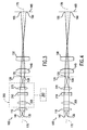
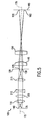
- Figs. 3-5 are sagittal views of an anamorphic zoom lens system 200 disposed within a dual-spot ROS system 105.
- Light-emitting devices 135, 140 preferably laser diodes, emit light beams, preferably laser beams, to encounter light-transmissive optics including zoom lens system 200.
- Laser diodes 135, 140 preferably are symmetrically disposed about axis 170.
- the beams emitted by laser diodes 135, 140 pass collimator lens 110 and zoom lens system 200 and are focused to form spots 125, 130 on a rotating reflective surface 120, such as a rotating polygon facet. Facet 120 reflects spots 125, 130 through post-polygon optics, such as F ⁇ lens 145 and polygon wobble correcting element 150, to form spots 155, 160 on image plane 165, which preferably is a photoreceptor surface. Spots 155, 160 are spaced along the sagittal meridian, producing scan line separation.
- the zoom system illustrated in Figs. 3-5 includes three optical elements or lenses 205, 210, 215.
- Lenses 205, 210 and 215 preferably are cylindrical lenses.
- zoom system 200 can include any number of lenses greater than one.
- Zoom lens systems, including mechanically compensated zoom systems, are discussed generally in Smith, Modern Optical Engineering , McGraw-Hill Book Company, 1966, pp. 241-245.
- zoom system 200 produces desired different optical magnifications along the sagittal meridian. Specifically, zoom system 200 adjusts magnification along the sagittal meridian to adjust scan line spacing, but does not adjust magnification along the tangential direction, so that no scan line distortion occurs. In other applications, including non-printing applications, change in magnification along both meridians may be acceptable.
- the motion of lens 215 is computed to hold the distance from lens 205 to the focal point at a constant value as lens 210 is moved to produce different magnification.
- a positioning device 203 such as a commercially available lens actuator, is coupled with zoom lens system 200 to position lenses 205, 210 and/or 215 of zoom lens system 200 as needed.
- Figs. 3, 4 and 5 respectively illustrate relative positions of the three lenses of zoom system 200 for nominal, long-limit and short-limit effective focal lengths.
- facet surface 120 reflects the light beams generated by laser diodes 135, 140 to form scan lines on photoreceptor surface 165.
- zoom system 200 can include any number of elements greater than one, not just the three elements 205, 210 and 215.
- Zoom system 200 preferably is used during manufacture of device 105 to adjust scan line spacing to correct scan line separation error.
- actual pre-polygon magnification was 11.77 instead of the desired 12.5, yielding a scan line separation error of 18.5 ⁇ m.
- the 18.5 ⁇ m error is detected, preferably during initial testing, and corrected by adjusting the positions of lenses 210 and 215.
- the 18.5 ⁇ m error thus can be eliminated, or at least reduced to a level at which the error can not be perceived in the printed image, without remanufacturing any of the system lenses and without repositioning any fixed lenses.
- separation error caused by imperfect laser spacing can be corrected without moving lasers 135, 140, and error produced by other elements can be corrected without moving or remanufacturing the other elements.
- correcting separation error with zoom system 200 occurs without defocusing spots 125, 130 on facet surface 120.
- facet surface 120 also does not need to be moved. Moving facet surface 120, of course, would require substantial redesign of the overall geometry of device 105.
- zoom system 200 is locked to fix the positions of lenses 205, 210 and 215.
- Device 105 then is ready for immediate use or for sale to an end user.
- Prior art zoom systems are unacceptable for use in ROS systems such as printing devices, because prior art zoom systems are not anamorphic.
- Using a non-anamorphic zoom system in a ROS printing device would produce unacceptable distortion in the tangential direction, that is, in the fast-scan direction of the printed image.
- anamorphic zoom system 200 there is no magnification in the tangential direction, and thus no distortion. Magnification changes only in the sagittal direction, allowing scan line spacing to be adjusted without distorting the scan lines themselves. Additionally, magnification can be changed without defocusing the spots on polygon surface 120 or the scan lines on photoreceptor surface 165.
Landscapes
- Physics & Mathematics (AREA)
- General Physics & Mathematics (AREA)
- Optics & Photonics (AREA)
- Mechanical Optical Scanning Systems (AREA)
- Laser Beam Printer (AREA)
Applications Claiming Priority (2)
| Application Number | Priority Date | Filing Date | Title |
|---|---|---|---|
| US357238 | 1989-05-24 | ||
| US35723894A | 1994-12-01 | 1994-12-01 |
Publications (1)
| Publication Number | Publication Date |
|---|---|
| EP0715197A2 true EP0715197A2 (de) | 1996-06-05 |
Family
ID=23404837
Family Applications (1)
| Application Number | Title | Priority Date | Filing Date |
|---|---|---|---|
| EP95308689A Withdrawn EP0715197A2 (de) | 1994-12-01 | 1995-12-01 | Anamorphotisches Zoomlinsensystem zur Kontrolle des Abtastlinienabstandes |
Country Status (2)
| Country | Link |
|---|---|
| EP (1) | EP0715197A2 (de) |
| JP (1) | JPH08234126A (de) |
Cited By (3)
| Publication number | Priority date | Publication date | Assignee | Title |
|---|---|---|---|---|
| EP0843192A1 (de) * | 1996-11-13 | 1998-05-20 | Canon Kabushiki Kaisha | Optisches Abtastsystem |
| WO2002088823A1 (en) * | 2001-04-27 | 2002-11-07 | Q-Vis Limited | Optical beam delivery configuration |
| KR100588459B1 (ko) | 2006-03-20 | 2006-06-12 | (주)큐엠씨 | 레이저 빔 전달 시스템 및 그 형성 방법 |
-
1995
- 1995-11-22 JP JP30449695A patent/JPH08234126A/ja not_active Withdrawn
- 1995-12-01 EP EP95308689A patent/EP0715197A2/de not_active Withdrawn
Cited By (6)
| Publication number | Priority date | Publication date | Assignee | Title |
|---|---|---|---|---|
| EP0843192A1 (de) * | 1996-11-13 | 1998-05-20 | Canon Kabushiki Kaisha | Optisches Abtastsystem |
| US6268877B1 (en) | 1996-11-13 | 2001-07-31 | Canon Kabushiki Kaisha | Scanning optical device featuring optical system image magnifications in main and subscanning directions within a prescribed range |
| WO2002088823A1 (en) * | 2001-04-27 | 2002-11-07 | Q-Vis Limited | Optical beam delivery configuration |
| US7173745B2 (en) | 2001-04-27 | 2007-02-06 | Q-Vis Limited | Optical beam delivery configuration |
| KR100588459B1 (ko) | 2006-03-20 | 2006-06-12 | (주)큐엠씨 | 레이저 빔 전달 시스템 및 그 형성 방법 |
| WO2007108589A1 (en) * | 2006-03-20 | 2007-09-27 | Qmc Co., Ltd. | An adjustable laser beam delivery system and method for forming the same |
Also Published As
| Publication number | Publication date |
|---|---|
| JPH08234126A (ja) | 1996-09-13 |
Similar Documents
| Publication | Publication Date | Title |
|---|---|---|
| CA2136671C (en) | Multiple beam raster output scanner optical system having telecentric chief exit rays | |
| EP1085743B1 (de) | Optisches Abtastgerät mit mehreren Strahlen und Vorrichtung zur Bilderzeugung das dasselbe benutzt | |
| US5526166A (en) | Optical system for the correction of differential scanline bow | |
| KR100982396B1 (ko) | 광주사 장치 및 그것을 이용한 화상 형성 장치 | |
| EP0659011B1 (de) | Schwankungs- und Bogenkorrektur durch Intensitätsproportionierung von mehreren Bildelementpunkten | |
| EP0713323B1 (de) | Vielpunkt-Polygonrasterausgabeabtaster mit optimierter Linienabstandsschärfentiefe | |
| EP0686862B1 (de) | 2-Linsiges Zoom-System zur Abstandskorrektur von Lichtstrahlen | |
| US5543829A (en) | Method and apparatus for adjusting the curvature of a folding mirror in a raster scanning system | |
| KR100516892B1 (ko) | 멀티빔 광학주사장치 및 화상 형성장치와 그것을 이용한컬러화상 형성장치 | |
| EP1107038B1 (de) | Optisches Mehrstrahlabtastsystem und Bilderzeugungsvorrichtung unter Verwendung desselben | |
| US5617133A (en) | Method and apparatus for adjusting orientation of light beams in a raster scanning system | |
| EP0631166B1 (de) | Rasterscanner mit Abtastbogenfehlerkompensation | |
| US20030043441A1 (en) | Multi-beam scanning optical system and image forming apparatus using the same | |
| EP1411380B1 (de) | Optische Abtastvorrichtung | |
| US20030137580A1 (en) | Light beam scanning method and apparatus | |
| JPH08234126A (ja) | ラスタ走査光学システム | |
| EP0782928B1 (de) | Farbxerographischer Drucker mit vielfachen linearen Reihen von oberflächenemittierenden Lasern mit gleichen Wellenlängen | |
| JPH04101112A (ja) | マルチビーム走査光学系 | |
| JP2000180749A (ja) | 光走査装置 | |
| EP2008077A1 (de) | Vorrichtung und verfahren zur verminderung der bandenartefaktsichtbarkeit bei einem scanning-gerät | |
| JP3470040B2 (ja) | カラー画像形成装置 | |
| JP2003344796A (ja) | 走査光学装置 |
Legal Events
| Date | Code | Title | Description |
|---|---|---|---|
| PUAI | Public reference made under article 153(3) epc to a published international application that has entered the european phase |
Free format text: ORIGINAL CODE: 0009012 |
|
| AK | Designated contracting states |
Kind code of ref document: A2 Designated state(s): DE FR GB |
|
| STAA | Information on the status of an ep patent application or granted ep patent |
Free format text: STATUS: THE APPLICATION HAS BEEN WITHDRAWN |
|
| 18W | Application withdrawn |
Withdrawal date: 19980316 |