EP0715723B1 - Mesure de l'intervalle de temps d'une forme d'onde en salve/sinusoidale - Google Patents
Mesure de l'intervalle de temps d'une forme d'onde en salve/sinusoidale Download PDFInfo
- Publication number
- EP0715723B1 EP0715723B1 EP94924527A EP94924527A EP0715723B1 EP 0715723 B1 EP0715723 B1 EP 0715723B1 EP 94924527 A EP94924527 A EP 94924527A EP 94924527 A EP94924527 A EP 94924527A EP 0715723 B1 EP0715723 B1 EP 0715723B1
- Authority
- EP
- European Patent Office
- Prior art keywords
- time
- phase
- phase voltage
- signal
- unknown
- Prior art date
- Legal status (The legal status is an assumption and is not a legal conclusion. Google has not performed a legal analysis and makes no representation as to the accuracy of the status listed.)
- Revoked
Links
- 238000000034 method Methods 0.000 claims description 13
- 230000008878 coupling Effects 0.000 claims description 10
- 238000010168 coupling process Methods 0.000 claims description 10
- 238000005859 coupling reaction Methods 0.000 claims description 10
- 238000001514 detection method Methods 0.000 claims description 9
- 230000003071 parasitic effect Effects 0.000 claims description 5
- 238000002347 injection Methods 0.000 claims description 4
- 239000007924 injection Substances 0.000 claims description 4
- 210000004027 cell Anatomy 0.000 description 16
- 238000004891 communication Methods 0.000 description 12
- 238000010586 diagram Methods 0.000 description 12
- 230000007935 neutral effect Effects 0.000 description 9
- 238000012360 testing method Methods 0.000 description 7
- 230000005540 biological transmission Effects 0.000 description 3
- 238000009434 installation Methods 0.000 description 3
- 101000860173 Myxococcus xanthus C-factor Proteins 0.000 description 2
- 238000005191 phase separation Methods 0.000 description 2
- 238000009420 retrofitting Methods 0.000 description 2
- 230000004075 alteration Effects 0.000 description 1
- 230000009286 beneficial effect Effects 0.000 description 1
- 230000015556 catabolic process Effects 0.000 description 1
- 238000006731 degradation reaction Methods 0.000 description 1
- RDYMFSUJUZBWLH-UHFFFAOYSA-N endosulfan Chemical compound C12COS(=O)OCC2C2(Cl)C(Cl)=C(Cl)C1(Cl)C2(Cl)Cl RDYMFSUJUZBWLH-UHFFFAOYSA-N 0.000 description 1
- 238000003780 insertion Methods 0.000 description 1
- 230000037431 insertion Effects 0.000 description 1
- 238000013507 mapping Methods 0.000 description 1
- 238000012986 modification Methods 0.000 description 1
- 230000004048 modification Effects 0.000 description 1
- 230000006855 networking Effects 0.000 description 1
- 210000002569 neuron Anatomy 0.000 description 1
- 230000000644 propagated effect Effects 0.000 description 1
- 238000000926 separation method Methods 0.000 description 1
- 230000001360 synchronised effect Effects 0.000 description 1
- 238000012546 transfer Methods 0.000 description 1
Images




Classifications
-
- G—PHYSICS
- G01—MEASURING; TESTING
- G01R—MEASURING ELECTRIC VARIABLES; MEASURING MAGNETIC VARIABLES
- G01R31/00—Arrangements for testing electric properties; Arrangements for locating electric faults; Arrangements for electrical testing characterised by what is being tested not provided for elsewhere
- G01R31/40—Testing power supplies
-
- G—PHYSICS
- G01—MEASURING; TESTING
- G01R—MEASURING ELECTRIC VARIABLES; MEASURING MAGNETIC VARIABLES
- G01R29/00—Arrangements for measuring or indicating electric quantities not covered by groups G01R19/00 - G01R27/00
- G01R29/18—Indicating phase sequence; Indicating synchronism
Definitions
- the present invention relates to an apparatus and a methed relative phase angle identification or determination in polyphase electrical power distribution system.
- Polyphase systems include two phase and three phase systems. Three phase systems offer economic and operating advantages, and are the most common. The respective voltages of a three phase system are normally generated by the same machine or generator.
- a power load may utilize all of the phases or a single phase of a polyphase power distribution system. For example, machinery found a in heavy industrial environment frequently draws power from all three phases. Other loads may only be connected across any one of the phases (line and the neutral). The majority of electrical products sold for general use are intended for connection to a single phase.
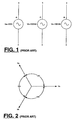
- Figure 1 shows three voltage sources Va, Vb, and Vc in a three phase system.
- Each source may be, for example, one hundred volts, as measured across the generating source.
- Source Va for example, is one hundred volts, as measured from a voltage point "a" to a point "o.” If the generating source Va is taken as the reference with a phase angle of zero (0) degrees, then the phase angle of Vc will be one hundred twenty (120) degrees and the phase angle of Vb will be two hundred forty (240) degrees.
- a phasor diagram of the three sources Va, Vb, and Vc is shown in Figure 2. Shown in the figure are source Va at 0 degrees, source Vc at 120 degrees, and source Vb at 240 degrees. Note that source Vb may also be measured as having a phase angle of negative 120 degrees. Thus, the relationship between each of the sources Va, Vb, and Vc in the three phase system is that each source is 120 degrees out of phase with the other generating sources.
- the three sources Va, Vb, and Vc of Figure 1 may be connected with their respective "o" points tied together to form a Y-connection, as shown in Figure 3.
- the three sources Va, Vb, and Vc may be connected with each "o" point joined to a corresponding voltage point of another source, as shown in Figure 4.
- the configuration of Figure 4 is known as a delta-connection.
- lines which extend from the voltage sources Va, Vb, and Vc form the three phases distribution system.
- the common point (or neutral) may or may not be distributed as a fourth line. If the neutral is distributed then the system is a four-wire three phase system.
- the delta-configuration of Figure 4 there is no neutral.
- the four wire three phase system of Figure 3 is almost universally used to distribute power within commercial buildings, and hence the presently preferred embodiment is described using this configuration.
- the present invention may also be used with a two phase or delta-distribution system.
- Power lines may not be ideal for data communication media, since power line characteristics do not readily transmit frequencies needed for useful data rates.
- the inductance and the loading of equipment connected across these power lines causes attenuation of the data signals, for example.
- appliances such as motors, light dimmers, switching mode power supplies, television (TV) sets, and fluorescent light ballasts couple noise on to the power lines which can degrade data communication signals.
- data signals on one phase are coupled to other phases by means of parasitic inductance and capacitance between distribution lines and within distribution transformers.
- the present invention relies on the parasitic coupling between phases for transmission of data packets across polyphases distribution system.
- the present invention does not require the degree of parasitic coupling needed by control or data systems, as only small amounts of data need to be successfully communicated with relatively low reliability.
- Phase Identification involves the determination of the relative phases of power outlets with respect to each other. If upon installation of a power line communication system it is found that there is high signal attenuation between the phases (i.e., insufficient transmitted signal propagated from a reference phase outlet to another outlet of a phase being tested) then appropriate network components or devices may be inserted to overcome the degradation of the signal.
- Patent Abstracts of Japan vol. 7, no. 164(P-211) [1309], 19 July 1983 & JP-A-58-072067 disclose an apparatus and a method which determine in a polyphase electrical power distribution system whether an unknown phase voltage is in synchronism with a reference phase voltage or not.
- a first circuit generates a short first signal at a first point in time, when the reference phase voltage crosses the zero point with positive slope. This signal is transformed and transmitted as an RF signal to a second circuit, then retransformed and finally applied to one input of a comparator. A second signal which is generated at a second point in time when the unknown phase voltage crosses zero with positive slope is applied to the other input of the comparator.
- the comparator determines whether both signals occur simultaneously or not and thereby discriminates between synchronised and unsynchronised phase voltages.
- US-A-3 469 082 teaches to inject a signal onto a reference phase power line of a polyphase electrical power distribution system.
- EP-A-0 146 425/US-A-4,626,622 teach to identify an unknown phase within a polyphase network by comparing that unknown phase with a known reference phase of that network. This is done by digitalization of the analog sinusoidal phase voltage signals of the two phases and then comparing these digital signals in a detection circuit which identifies whether the unknown phase is "in phase”, “180° out of phase”, “leading” or “lagging” vis-a-vis the reference phase.
- the present invention provides by the subjects matters of its claims 1 or 6 an effective means for identifying the individual relative phases at each electrical outlet of a building having a polyphase electrical power distribution system.
- the apparatus of the present invention includes a transmitting unit and a receiving unit.
- the transmitting unit can be plugged into an electrical outlet.
- the phase of that outlet will be treated as the reference phase against which the phase at other outlets will be compared.
- the transmitting unit injects a data packet onto the reference phase outlet at a predetermined point on the AC waveform.
- the prefered embodiment injects a data packet at the point where the sinusoidal voltage of the reference phase is approximately zero and is positive-going with respect to the neutral line. It should be noted that any point on the AC waveform could be chosen as the data packet injection point. For simplicity, only the zero cross-over with a positive slope point will be described herein.
- the receiver is a portable unit that can be plugged into an electrical outlet where the phase is unknown.
- the receiver unit is able to recelve the data packet from the transmitter unit over the power lines and can also detect each point in time when the AC voltage of the unknown phase is crossing zero voltage with a positive slope.
- the receiver unit can then determine the phase angle and identify the unknown phase relative to the reference phase based on the amount of time measured between reception of the data packet and detection of the point in time when the voltage of the unknown phase is zero-crossing with positive slope.
- the transmitter unit is connected to the reference electrical outlet having a reference phase, and places a reference data packet on the power line at each point in time when the phase voltage is zero-crossing with a positive slope.
- the receiver unit is connected to an electrical outlet having an unknown phase. The receiver unit can then receive the reference data packet, and can determine the positive going sinusoidal voltage phase zero-cross-over point.
- the receiver unit upon reception of the reference data packet, starts a timer.
- the timer Is stopped at a point when the voltage at the unknown phase outlet is approximately zero with positive slope.
- the receiver unit then computes the difference between the start time and the stop time, and determines the phase angle of the unknown phase relative to the reference phase, based upon that computed difference.
- phase angle separates the several sources. That is, the different generating sources achieve different voltage values at different times because their phase angles are different from one another.
- the phase separation is 120 degrees between each phase. While, the instantaneous voltage of any one phase may be calculated, for simplicity, only the zero-cross-over points with positive slope will be considered here for this application. Thus, if at a given time the phase voltage of Phase A is 0 volts, then the corresponding zero-cross-over of phase B will be at 120 degrees relative to phase A, and the respective zero cross-over of Phase C would be 240 degrees relative to Phase A. A two phase system would have a phase separation of 180 degrees.
- any one of the three phases can be used as a reference phase, and the other two phases can be identified by their respective zero-cross-over points, relative to the reference phase zero cross-over.
- the Phase A zero cross-over with a positive slope as a reference for example, the occurrence in time of the Phase B and Phase C zero-cross-overs can be determined. This procedure can effectively provide relative phase identification for the three phases in a building.
- the unknown phase zero-cross-over occurs at 5.56 ms after the reference phase zero-cross over, then the unknown phase is lagging the reference phase by 120 degrees. Looking at Figure 5, if the reference zero-cross-over is at point A, then the signal having a zero-cross-over 5.56 ms after point A is the Phase B signal.
- the presently preferred embodiment uses a transmitter unit and a receiver unit.
- the transmitter unit is connected into a phase which is to be used as the reference, and the receiver unit is portable and can be taken around the building to the outlets having phases which need to be identified.
- the transmitter unit and the receiver unit are symbolically represented in Figure 6 at 101 and 103, respectively.
- the two units 101 and 103 plug into electrical outlets 105 and 107, respectively.
- the representation of the transmitter unit 101 shows the signal 109 that the transmitter unit 101 receives from electrical outlet 105.
- This signal 109 is assumed to be of Phase A in the presently preferred embodiment:
- the receiver unit 103 receives a signal 111 from electrical outlet 107.
- this signal 111 is assumed to be of Phase B.
- a dashed line 109A represents the relative position of the Phase A signal 109.
- the dashed line 109A is shown for reference only, and is not received from electrical outlet 107.
- the transmitter unit 101 senses each positive going slope zero-cross-over of the Phase A signal 109 and injects a short data packet 113 of the data carrier frequency onto the power line via outlet 105.
- the receiver unit 103 receives the small data packet 113 which was sent by the transmitter unit 101, and uses that as an indicator of the reference phase zero-cross-over.
- the dashed line 109A shows the position of the reference Phase A signal 109 superimposed on the unknown signal 111.
- the receiver unit 103 uses the reception of the data packet 113 as a time-zero stamp, and times from that to the zero-cross-over point with positive slope of the unknown phase 111 in order to determine the phase angle of the unknown phase 111.
- the time is 5.56 ms, which means that the unknown phase 111 is determined to be of Phase B.
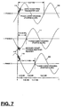
- Figure 7 shows the injection of a data packet 113 onto reference signal 109 (which is of Phase A in this example) at the Phase A positive-going-slope zero-cross-over.
- the receiver unit 103 detects the data packet 113 and starts timer. On detecting a positive-slope zero-cross-over, the timer is stopped and a reading the timer shows a value of 5.5.6 ms. If the receiver unit 103 were connected to a Phase C electrical outlet, for example, then a time of 11.11 ms from reception of the data packet 113 to detection of the positive-slope zero-cross-over of the Phase C signal would indicate that the reference signal was of Phase C.
- the transmitter unit 101 is connected to the reference electrical outlet 105 having a reference signal 109 with a reference phase.
- the receiver unit 103 is connected to a test electrical outlet 107 having a test signal 111 with an unknown phase.
- the transmitter unit 101 senses a point in time when the voltage of the reference signal 109 is approximately zero with positive slope (at Step 205), and at Step 207 inserts a data packet 113 into the reference signal 109.
- the receiver unit 101 receives the data packet 113 at Step 209, and upon such reception starts a timer at Step 211.
- the receiver unit 103 also senses a point in time when the voltage of the unknown phases 111 is approximately zero with positive slope (at Step 213), and stops the timer at that time as shown at Step 215.
- the receiver unit 103 then computes the difference between the start time and the stop time at Step 217.
- the receiver unit 103 determines the phase angle of the test phase relative to the reference phase based upon that computed difference.
- the circuitry of the transmitter unit 101 of the presently preferred embodiment is shown in Figure 9, and the circuitry of the receiver unit 103 of the presently preferred embodiment is shown in Figure 10.
- both units comprise the same hardware, and can be configured as transmitter unit 101 or as receiver unit 103 according to the "JP1" and "JP2" switches.
- the units 101, 103 can be configured as 60 Hz units or 50 Hz units, the latter being for operation in Europe, according to the "JP1" and "JP2" switches.
- the transmitter unit 101 is configured with the JP1 switch closed (transmitter mode) and with the JP2 switch open (60 Hz mode), and the receiver unit 103 is configured with the JP1 switch open (receiver mode) and with the JP2 switch open (60 Hz mode).
- the transmitter unit 101 of Figure 9 uses a time out indicator 115, which is a light emitting diode (LED).
- Receiver unit 103 uses 5 LEDs: a data packet detection indicator LED 117; an inverted phase indicator LED 119; a Phase A indicator LED 121; a Phase B indicator LED 123; and a Phase C indicator LED 125.
- the data packet detection indicator LED 117 when activated, indicates communication between the transmission unit 101 and the receiver unit 103. For instance, if the line connected to the transmission unit 101 is isolated from the line connected to the receiver unit 103 then LED 117 would not be lit, thus indicating that the receiver unit 103 is not receiving data packets.
- the inverted phase detector LED 119 indicates that the receiver unit 103 is detecting a packet that is 180 degrees out of phase.
- the time between the zero-crossing of the reference phase and the test phase will be 8.33 ms. The above shows that this invention will work equally well in two phase environments as well.
- the receiver unit 103 may find the reference phase to be: Phase A in which case the Phase A indicator LED 121 is activated; Phase B in which case the Phase B indicator LED 123 is activated; or Phase C in which case the Phase C indicator LED 125 is activated.
- the inverted phase detector LED 119 in the case where a phase line was wired incorrectly such that that phase is 180 degrees out of phase with what it should be, the inverted phase detector LED 119 is activated. For example, if an electrical outlet having a Phase A signal was incorrectly wired, then the positively sloped zero-cross-overs occur when the negatively sloped zero-cross-overs should occur and vice-versa. Two phase 180 degrees out of phase power wiring situations are quite common for private dwellings in the USA.
- the zero-cross detector 127 of Figures 9 and 10 identifies each phase positive-going zero-cross-over in order to start operations, such as when to send a data packet on the line in the case of the transmitter unit 101 configuration.
- the zero-cross detector 127 detects each zero-cross-over with positive slope so that the receiver unit 103 can stop a timer (which may be located within cell 129) to determine the time between the time that the data packet 113 is received and the zero-cross-over.
- the cell 129 of Figures 9 and 10 is the controlling processor and is application driven.
- the NEURON® Chip which is a product of the Assignee of the present invention, is implemented as cell 129.
- the cell 129 controls timing functions, drives the LED indicators, and handles communications with the power line modem 131 (also a product of the Assignee of the present invention) to send and receive data packets 113.
- the power line modem 131 In the transmitter unit 101 configuration of Figure 9, the power line modem 131, when instructed by cell 129, places a data packet on the line 133. Amplifier 140 amplifies the data packet signal. In the receiver unit 103 configuration of Figure 10, the power line modem 131 monitors the line 135 for incoming data packets 113, receives the data packets 113, and forwards the data packets 113 to the cell 129.
- the power line modem 131 has a transmitting section 139 and a receiving section 141.
- the power line coupling 137 of Figures 9 and 10 blocks the unwanted 60 Hz low frequency contents (50 Hz in the case of European operation) of the line.
- the power line coupling 137 in the case of the transmitter unit 101 configuration, couples the high frequency data carrier signal (data packet) to the line 133.
- the power line coupling 137 couples the data packet from the line 135 to the receiver section 141 of the power line modem 131.
- the frequency of the data packet is between 100 Khz and 450 KHz. Other frequencies, however, may be used.
- the information contained in the data packet can be any sequence of logical "0"s and "1"s recognizable by a receiver.
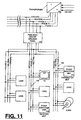
- FIG. 11 A block diagram showing the transmitter unit 101 and the receiver unit 103 operating in a typical three phase power distribution system is shown in Figure 11.
- Transformer 143 outputs a ground, neutral, Phase A, Phase B, and Phase C.
- the ground and neutral are shorted together at the transformer 143, and usually the power is defined between the neutral and the phase lines.
- the ground usually serves as a safety line.
- These five lines are fed through a circuit breaker panel 145 and then into a typical distribution in a building, for example.
- Single phase loads, such as television 147, are each connected between a single phase, such as Phase B and neutral.
- the transmitter unit 101 is shown connected to a Phase A line and the receiver unit 103 is shown connected to a Phase B line.
- the zero-cross detector 127 detects each positively sloped zero-cross-over and indicates to cell 129 that the crossover has occured which in turn instructs the power line modem 131 to put a small data packet 113 onto line 133.
- each data packet 113 is approximately 3 ms in duration .
- the data packet is amplified by amplifier 140 and then placed on line 133 via the power line coupling 137.
- the packet propagates on the line on the particular phase, in this case Phase A.
- the receiver unit 103 of Figure 10 may be on the same phase as the transmitter unit 101 or another phase, in this case Phase B.
- the data packet 113 passes through the power line coupling 137 and into the power line modem 131.
- the power line modem 131 distinguishes that the data packet 113 is not noise and is a valid packet.
- the power line modem 131 then sends the data packet 113 to cell 129.
- the zero-cross detector 127 monitors the line 135 and sends a pulse to the cell 129 when a positively sloped zero-cross-over occurs.
- the cell 129 associates the time that the data packet 113 was received with the time that the zero-cross-over on line 135 occurred. If the times of both the receipt of the data packet 113 and the zero-cross-over are the same, then the test phase on line 135 is the same phase as the reference phase. If the time difference is 5.56 ms or 11.11 ms then the cell 129 determines that the phase is Phase B or Phase C.
- the cell 129 determines the inverted phase as follows. If the phase on line 135 is Phase A, inverted, then the zero-cross-over would be detected 8.33 ms after reception of the data packet 113. If the phase on line 135 is Phase B, inverted, then the zero-cross-over would be detected 2.78 ms before reception of the data packet 113 (or 13.89 ms after reception of the data packet). If the phase on line 135 is Phase C, inverted, then the zero-cross-over would be detected 2.78 ms after reception of the data packet 113.
- the cell 129 of the receiver unit 103 performs the above procedure approximately fifty times in the presently preferred embodiment before indicating a result. After fifty valid data packets are received at the appropriate times, then the cell 129 of the receiver unit 103 indicates the appropriate LED indicator combinations. For example, if line 135 has an inverted Phase B signal, then LEDs 119 and 123 are activated. The receiving unit 103 continues the above procedure, gathering data beyond fifty samples, to eliminate false data.
- a user can repeat the above procedure, moving the receiving unit 103 from outlet to outlet, for example, until a desired representation of the wiring of a building is developed.
- the reference phase is arbitrarily labeled Phase A, even if this phase is actually Phase B or C.
- the relative phase differences among the phases in the building and inversions thereof are accurately determined with the present invention. Upon such mapping of the outlets in a building, retrofitting the building for networking may be performed effectively and efficiently.
- the circuits shown therein may be implemented without the power line modem 131 amplifier 140, and power line coupling 137.
- data packets may be generated and sent from cell 129 on some other medium, such as via an antenna over radio frequency (RF), for example.
- RF radio frequency
Landscapes
- Physics & Mathematics (AREA)
- General Physics & Mathematics (AREA)
- Cable Transmission Systems, Equalization Of Radio And Reduction Of Echo (AREA)
- Testing Of Short-Circuits, Discontinuities, Leakage, Or Incorrect Line Connections (AREA)
Claims (9)
- Dispositif pour identifier dans un réseau de distribution électrique polyphasé le déphasage et la phase de câblage (A ; B ; C) d'une tension de phase inconnue arbitraire (B ; C) par rapport à une tension de phase de référence (A), comprenant :un premier circuit (101) pour générer un paquet de données court ou signal horodateur (113) respectivement à un premier point dans le temps (T1) quand un premier point prédéterminé de la tension de phase de référence (A) est détecté,le premier circuit (101) comprenant des moyens d'injection (129, 131, 137, 139) pour injecter le paquet de données/signal horodateur (113) dans la tension de phase de référence (A) ; etun deuxième circuit (103) comprenant des moyens de réception (129, 131, 137, 141) pour recevoir de la tension de phase inconnue (B ; C) le paquet de données/signal horodateur (113) et des moyens (127) pour détecter un deuxième point dans le temps (T2) quand un deuxième point prédéterminé de la tension de phase inconnue (B ; C) se produit,le deuxième circuit (103) comprenant des moyens (129) pour mesurer l'intervalle de temps (T2-T1) entre la réception du paquet de données/signal horodateur (113) et le deuxième point dans le temps (T2) et des moyens (129) pour associer un déphasage relatif particulier à chacun des intervalles de temps mesurés (T2-T1).
- Dispositif selon la revendication 1, dans lequel les points prédéterminés des tensions de phase de référence et inconnue (A ; B ; C) sont définis par des valeurs de tension et des pentes des phases respectives (A ; B ; C) à ces valeurs de tension respectives.
- Dispositif selon la revendication 2, dans lequel la position relative du premier point sur la tension de phase de référence (A) est le même que la position relative du deuxième point de la tension de phase inconnue (B ; C), en particulier le point avec une tension nulle et une pente positive.
- Dispositif selon l'une quelconque des revendications 1 à 3, où la tension de phase inconnue (B ; C) et la tension de phase de référence (A) sont reliées par couplage parasite, dans lequel le premier circuit (101) injecte le paquet de données/signal horodateur (113) sur la tension de phase de référence (A) et le deuxième circuit (103) reçoit le paquet de données/signal horodateur (113) par l'intermédiaire du couplage parasite.
- Dispositif selon les revendications 3 et 4, dans lequelle premier circuit (101) comprenddes premiers moyens de détection (127) pour détecter chaque point dans le temps (T1) quand la tension de la tension de phase de référence (A) atteint le premier point prédéterminé etlesdits moyens d'injection (129, 131, 137, 139) pour injecter le paquet de données/signal horodateur (113) sur la tension de phase de référence (A) à chacun des points détectés dans le temps (T1) ; etle deuxième circuit (103) comprendlesdits moyens de réception (129, 131, 137, 141) pour recevoir chaque paquet de données/signal horodateur (113) ; etlesdits moyens (127) pour détecter chaque point dans le temps (T2) quand la tension de la tension de phase inconnue (B ; C) atteint le deuxième point prédéterminé.
- Procédé pour identifier dans un réseau de distribution électrique polyphasé le déphasage et la phase de câblage (A ; B ; C) d'une tension de phase inconnue arbitraire (B ; C) par rapport à une tension de phase de référence (A), comprenant les étapes suivantes consistant à :injecter un signal court (113) dans la tension de phase de référence (A) quand un premier point déterminé de la tension de phase de référence (A) est détecté ;recevoir de la tension de phase inconnue (B ; C) le signal (113) ;détecter quand un deuxième point prédéterminé de la tension de phase inconnue (B ; C) apparaít ; etassocier un déphasage particulier entre la tension de phase inconnue (B ; C) et la tension de phase de référence (A) à l'intervalle de temps (T2-T1) entre la réception du signal (113) et la détection de quand le point déterminé de la tension de phase inconnue (B ; C) apparaít.
- Procédé selon la revendication 6, dans lequel la position relative du premier point prédéterminé situé sur la tension de phase de référence (A) est le même que la position relative du deuxième point prédéterminé situé sur la tension de phase inconnue (B ; C), en particulier la position où la tension de phase (A ; B ; C) atteint zéro avec une pente positive.
- Procédé selon la revendication 6 ou 7, comprenant en outre les étapes suivantes consistant à :connecter un premier circuit (101) à une première prise de courant électrique (105) du réseau de distribution électrique, la première prise de courant électrique (105) ayant un signal de référence (109) avec une tension de phase de référence (A) ;connecter un deuxième circuit (103) à une deuxième prise de courant électrique (107) du réseau de distribution électrique, la deuxième prise de courant électrique (107) ayant un signal inconnu (111 ; 222) avec une tension de phase inconnue (B ; C) ;détecter chaque premier point dans le temps (T1) quand la tension du signal de référence (109) dans la première prise de courant électrique (105) atteint le premier point prédéterminé ;envoyer comme signal court (113) un paquet de données court ou signal horodateur respectivement du premier circuit (101) au deuxième circuit (103) à chacun des premiers points prédéterminés (T1) ;recevoir chaque paquet de données/signal horodateur (113) par le deuxième circuit (103) ;détecter chaque deuxième point dans le temps (T2) quand la tension du signal inconnu (111 ; 222) atteint le deuxième point prédéterminé ; etdéterminer l'intervalle de temps (T2-T1) mesuré entre la réception d'un paquet de données/signal horodateur (113) et la détection du deuxième point dans le temps (T2).
- Procédé selon la revendication 8, où la tension de phase inconnu (B ; C) est reliée par coulage parasite à la tension de phase de référence (A), dans lequel
un circuit émetteur est utilisé comme premier circuit (101) ;
un circuit récepteur est utilisé comme deuxième circuit (103) ;
le paquet de données/signal horodateur (113) est inséré dans le signal de référence (A) ;
le paquet de données/signal horodateur (113) est reçu par l'intermédiaire du couplage parasite avec le circuit récepteur ;
une minuterie (129) est déclenchée à un temps de départ (T1) à la réception du paquet de données/signal horodateur (113);
le deuxième point prédéterminé situé sur le signal inconnu (B ; C) est détecté ;
la minuterie (129) est arrêtée à un temps d'arrêt (T2) à la détection du deuxième point prédéterminé situé sur le signal inconnu (B ; C) ;
la différence de temps (T2-T1) entre le temps de départ (T1) et le temps d'arrêt (T2) est calculé ; et
un déphasage particulier de la tension de phase inconnue (B ; C) par rapport à la tension de phase de référence (A) est associé à la différence de temps calculée (T2-T1).
Applications Claiming Priority (3)
| Application Number | Priority Date | Filing Date | Title |
|---|---|---|---|
| US11115093A | 1993-08-23 | 1993-08-23 | |
| US111150 | 1993-08-23 | ||
| PCT/US1994/008616 WO1995006260A1 (fr) | 1993-08-23 | 1994-08-02 | Mesure de l'intervalle de temps d'une forme d'onde en salve/sinusoidale |
Publications (3)
| Publication Number | Publication Date |
|---|---|
| EP0715723A1 EP0715723A1 (fr) | 1996-06-12 |
| EP0715723A4 EP0715723A4 (fr) | 1997-04-23 |
| EP0715723B1 true EP0715723B1 (fr) | 2003-06-11 |
Family
ID=22336871
Family Applications (1)
| Application Number | Title | Priority Date | Filing Date |
|---|---|---|---|
| EP94924527A Revoked EP0715723B1 (fr) | 1993-08-23 | 1994-08-02 | Mesure de l'intervalle de temps d'une forme d'onde en salve/sinusoidale |
Country Status (5)
| Country | Link |
|---|---|
| US (1) | US5521491A (fr) |
| EP (1) | EP0715723B1 (fr) |
| AU (1) | AU7477494A (fr) |
| DE (1) | DE69432819T2 (fr) |
| WO (1) | WO1995006260A1 (fr) |
Families Citing this family (41)
| Publication number | Priority date | Publication date | Assignee | Title |
|---|---|---|---|---|
| CA2168941A1 (fr) * | 1996-02-06 | 1997-08-07 | Barna Szabados | Rheostat pour appareil d'eclairage fluorescent |
| DE19653323C2 (de) * | 1996-12-20 | 2001-07-12 | Beha C Gmbh | Vorrichtung zur Bestimmung des Vorzeichens einer Phasenverschiebung zweier elektrischer Signale |
| US5828293A (en) * | 1997-06-10 | 1998-10-27 | Northern Telecom Limited | Data transmission over a power line communications system |
| US6480510B1 (en) | 1998-07-28 | 2002-11-12 | Serconet Ltd. | Local area network of serial intelligent cells |
| US6549616B1 (en) | 2000-03-20 | 2003-04-15 | Serconet Ltd. | Telephone outlet for implementing a local area network over telephone lines and a local area network using such outlets |
| US6842459B1 (en) | 2000-04-19 | 2005-01-11 | Serconet Ltd. | Network combining wired and non-wired segments |
| JP3616324B2 (ja) * | 2000-11-27 | 2005-02-02 | 東京計装株式会社 | 伝播時間差方式による超音波流量計 |
| KR100835220B1 (ko) * | 2001-12-24 | 2008-06-05 | 재단법인 포항산업과학연구원 | Gps 수신기를 이용한 동시간 전력 측정 시스템 |
| US7031859B2 (en) * | 2002-03-11 | 2006-04-18 | Piesinger Gregory H | Apparatus and method for identifying cable phase in a three-phase power distribution network |
| US6667610B2 (en) * | 2002-03-11 | 2003-12-23 | Gregory Hubert Piesinger | Apparatus and method for identifying cable phase in a three-phase power distribution network |
| US6690151B2 (en) * | 2002-03-12 | 2004-02-10 | And Yet, Inc. | Phase detection circuit |
| US6642700B2 (en) | 2002-03-26 | 2003-11-04 | Avistar, Inc. | System, method, field unit, reference unit and computer program product for phase tracking of electrical conductors |
| FR2844600A1 (fr) * | 2002-09-13 | 2004-03-19 | Thomson Licensing Sa | Procede pour situer relativement deux appareils electriques |
| IL152824A (en) | 2002-11-13 | 2012-05-31 | Mosaid Technologies Inc | A socket that can be connected to and the network that uses it |
| US20040251921A1 (en) * | 2003-06-10 | 2004-12-16 | Sagab Electronic Ab | Method and device system for testing electrical components |
| WO2005039239A2 (fr) * | 2003-10-17 | 2005-04-28 | Power Control Technologies, Inc. | Dispositif de protection de ballast |
| IL160417A (en) | 2004-02-16 | 2011-04-28 | Mosaid Technologies Inc | Unit added to the outlet |
| US7088232B2 (en) * | 2004-03-03 | 2006-08-08 | Evans Wetmore | System and method for reducing radiation when distributing broadband communication signals over power lines |
| WO2005116668A1 (fr) * | 2004-05-25 | 2005-12-08 | Enel Distribuzione S.P.A. | Procede et appareil de detection d'une tension de phase inconnue par rapport a une tension de phase de reference |
| PL1779126T3 (pl) * | 2004-08-16 | 2010-08-31 | Enel Distribuzione Spa | Sposób oraz system do wykrywania fazy przewodu nieznanego napięcia fazowego względem napięcia fazowego odniesienia |
| US7873058B2 (en) | 2004-11-08 | 2011-01-18 | Mosaid Technologies Incorporated | Outlet with analog signal adapter, a method for use thereof and a network using said outlet |
| US20080164862A1 (en) * | 2005-03-21 | 2008-07-10 | Davide Tazzari | Method and Device For Determination of the Phases in a Multi-Phase Electrical System |
| DE602005023536D1 (de) * | 2005-04-06 | 2010-10-21 | Power One Italy Spa | Elektrizitätsverteilungsnetz mit streuspannungsüberwachung und verfahren zur übertragung von informationen in dem netz |
| US20070063664A1 (en) * | 2005-09-22 | 2007-03-22 | Avistar, Inc. | Phase identification apparatus having automatic gain control to prevent detector saturation |
| US7323968B2 (en) * | 2005-12-09 | 2008-01-29 | Sony Corporation | Cross-phase adapter for powerline communications (PLC) network |
| US7816903B2 (en) * | 2008-03-21 | 2010-10-19 | Smk Corporation | Single-phase 3-wire power line connection determination apparatus and connection determination method |
| US8315152B2 (en) | 2008-06-06 | 2012-11-20 | Maxim Integrated Products, Inc. | System and method for applying multi-tone OFDM based communications within a prescribed frequency range |
| US20100262393A1 (en) * | 2009-04-08 | 2010-10-14 | Manu Sharma | System and Method for Determining a Phase Conductor Supplying Power to a Device |
| US20100262395A1 (en) * | 2009-04-08 | 2010-10-14 | Manu Sharma | System and Method for Determining a Phase Conductor Supplying Power to a Device |
| US8320233B2 (en) * | 2009-06-12 | 2012-11-27 | Maxim Integrated Products, Inc. | Transmitter and method for applying multi-tone OFDM based communications within a lower frequency range |
| US8533121B1 (en) * | 2009-11-25 | 2013-09-10 | Gregory Hubert Piesinger | Method and apparatus for phase identification in a three-phase power distribution network |
| US20110285382A1 (en) * | 2010-05-18 | 2011-11-24 | General Electric Company | Power meter phase identification |
| US20120169322A1 (en) * | 2010-12-29 | 2012-07-05 | General Electric Company | Phase identification system and method |
| US8756449B2 (en) | 2011-03-08 | 2014-06-17 | Cisco Technology, Inc. | Phase-based operation of devices on a polyphase electric distribution system |
| US8810233B2 (en) | 2011-08-25 | 2014-08-19 | General Electric Company | Phase identification system and method |
| US9164135B2 (en) * | 2011-09-13 | 2015-10-20 | Honeywell International Inc. | System and method for measuring phase attributes of electrical grid system and equipment using a smart probe |
| TWI454713B (zh) * | 2012-01-19 | 2014-10-01 | Univ Ishou | Wireless measurement device, detection module |
| US9482709B2 (en) | 2012-05-22 | 2016-11-01 | Siemens Aktiengesellschaft | Method and device for assigning individual phase conductors in a polyphase energy distribution network |
| JP5879400B1 (ja) * | 2014-08-06 | 2016-03-08 | 志朗 白井 | 制御システム |
| JP6568744B2 (ja) * | 2015-08-18 | 2019-08-28 | 株式会社日本総合研究所 | 判定システム |
| JP7546923B2 (ja) | 2021-12-27 | 2024-09-09 | 共立電気計器株式会社 | 配線接続検査方法及び配線接続検査システム |
Family Cites Families (9)
| Publication number | Priority date | Publication date | Assignee | Title |
|---|---|---|---|---|
| US3469082A (en) * | 1966-04-29 | 1969-09-23 | Westinghouse Electric Corp | Phase measuring system for electric power networks |
| US4225966A (en) * | 1970-10-06 | 1980-09-30 | The United States Of America As Represented By The Secretary Of The Army | Power area collocation of transmitters |
| US3775676A (en) * | 1972-07-21 | 1973-11-27 | Westinghouse Electric Corp | Methods for locating partial discharges in electrical apparatus |
| US4011503A (en) * | 1975-10-16 | 1977-03-08 | Narco Scientific Industries, Inc. | Apparatus for measuring the phase relation of two alternating current signals |
| JPS5392155A (en) * | 1977-01-25 | 1978-08-12 | Tokyo Electric Power Co Inc:The | Method of detecting phase angle standard for phase pulse signal receiver |
| JPS5872067A (ja) * | 1981-10-26 | 1983-04-28 | Toko Denki Kk | 配電線の相判別方法 |
| CA1212416A (fr) * | 1983-11-15 | 1986-10-07 | Michel Bouvrette | Telephaseur pour l'identification des phases a distance de lignes de transport et/ou d'arteres dans un reseau electrique |
| CH668487A5 (de) * | 1985-05-21 | 1988-12-30 | Korona Messtechnik Gossau | Kontrollvorrichtung zur elektronischen detektion von energieverluste verursachenden fehlstellen bei wechselstrom-freileitungen. |
| US4680620A (en) * | 1986-03-06 | 1987-07-14 | Tektronix, Inc. | Measurement of SC/H phase using a subcarrier time mark generator and a calibrated phase shifter |
-
1994
- 1994-08-02 AU AU74774/94A patent/AU7477494A/en not_active Abandoned
- 1994-08-02 WO PCT/US1994/008616 patent/WO1995006260A1/fr not_active Ceased
- 1994-08-02 DE DE69432819T patent/DE69432819T2/de not_active Revoked
- 1994-08-02 EP EP94924527A patent/EP0715723B1/fr not_active Revoked
-
1995
- 1995-05-16 US US08/441,957 patent/US5521491A/en not_active Expired - Lifetime
Non-Patent Citations (1)
| Title |
|---|
| U. Tietze, Ch. Schenk, "Halbleiter-Schaltungstechnik", 5th edition, Springer Verlag Berlin, Heidelberg, NewYork, 1980, pages 709-711 * |
Also Published As
| Publication number | Publication date |
|---|---|
| DE69432819T2 (de) | 2004-05-06 |
| US5521491A (en) | 1996-05-28 |
| EP0715723A1 (fr) | 1996-06-12 |
| AU7477494A (en) | 1995-03-21 |
| EP0715723A4 (fr) | 1997-04-23 |
| WO1995006260A1 (fr) | 1995-03-02 |
| DE69432819D1 (de) | 2003-07-17 |
Similar Documents
| Publication | Publication Date | Title |
|---|---|---|
| US5521491A (en) | Phase detecting device for determining phase angle between two electrical signals | |
| CN1997900B (zh) | 用于检测任意未知相电压相对于参考相电压的相配线的方法和装置 | |
| KR101143024B1 (ko) | 누설전류검출장치와 방법 | |
| EP1505706A2 (fr) | Méthode et système de détermination en temps réel de l' énergie, l'emplacement et type d'un défaut d'arc | |
| US20030043027A1 (en) | Repeater amplifier with signal firewall protection for power line carrier communication networks | |
| US20020130768A1 (en) | Low voltage power line carrier communications at fundamental working frequency | |
| US20090045818A1 (en) | Power-over-ethernet isolation loss detector | |
| CA2068952A1 (fr) | Dispositif de mesure et de suivi de l'isolement dans un bloc d'alimentation electrique a neutre isole | |
| CA2333646C (fr) | Circuit electronique pour identifier un disjoncteur associe a un circuit derive | |
| US5754053A (en) | In service cable failure detector and method | |
| US7141960B2 (en) | Method and device system for testing electrical components | |
| JPH11204016A (ja) | 逆位相変圧器を利用した漏電警報/遮断装置 | |
| US7075310B2 (en) | Device and method for testing for a wiring fault condition | |
| AU2006219731B2 (en) | Method and apparatus for monitoring the earth loop impedance of an electrical installation | |
| US4532569A (en) | Method and apparatus for detecting improper polarity in a power distribution system | |
| KR101117870B1 (ko) | 누설전류검출장치와 방법 | |
| GB2635170A (en) | Fire Alarm System Testing | |
| JPS62233035A (ja) | 配電線遠方監視制御方式 | |
| JPH07119785B2 (ja) | 絶縁監視装置 | |
| JPS6171370A (ja) | 漏電警報装置 | |
| JPH01219999A (ja) | 電力線搬送制御インタフェースユニット | |
| JPS62181630A (ja) | 配電線位相差検出方法 | |
| JPH07134144A (ja) | 電灯線搬送機能付きロードサーベイメータ | |
| HK1116543B (en) | Leak current breaker and method | |
| JPS6218839A (ja) | 電力線搬送方式送受信回路 |
Legal Events
| Date | Code | Title | Description |
|---|---|---|---|
| PUAI | Public reference made under article 153(3) epc to a published international application that has entered the european phase |
Free format text: ORIGINAL CODE: 0009012 |
|
| 17P | Request for examination filed |
Effective date: 19960321 |
|
| AK | Designated contracting states |
Kind code of ref document: A1 Designated state(s): DE FR GB IE IT |
|
| A4 | Supplementary search report drawn up and despatched | ||
| AK | Designated contracting states |
Kind code of ref document: A4 Designated state(s): DE FR GB IE IT |
|
| 17Q | First examination report despatched |
Effective date: 19991216 |
|
| GRAH | Despatch of communication of intention to grant a patent |
Free format text: ORIGINAL CODE: EPIDOS IGRA |
|
| GRAH | Despatch of communication of intention to grant a patent |
Free format text: ORIGINAL CODE: EPIDOS IGRA |
|
| GRAA | (expected) grant |
Free format text: ORIGINAL CODE: 0009210 |
|
| AK | Designated contracting states |
Designated state(s): DE FR GB IE IT |
|
| REG | Reference to a national code |
Ref country code: GB Ref legal event code: FG4D |
|
| REG | Reference to a national code |
Ref country code: IE Ref legal event code: FG4D |
|
| REF | Corresponds to: |
Ref document number: 69432819 Country of ref document: DE Date of ref document: 20030717 Kind code of ref document: P |
|
| PLBQ | Unpublished change to opponent data |
Free format text: ORIGINAL CODE: EPIDOS OPPO |
|
| PLBI | Opposition filed |
Free format text: ORIGINAL CODE: 0009260 |
|
| ET | Fr: translation filed | ||
| PLAX | Notice of opposition and request to file observation + time limit sent |
Free format text: ORIGINAL CODE: EPIDOSNOBS2 |
|
| 26 | Opposition filed |
Opponent name: ENEL DISTRIBUZIONE S.P.A. Effective date: 20040311 |
|
| PLAX | Notice of opposition and request to file observation + time limit sent |
Free format text: ORIGINAL CODE: EPIDOSNOBS2 |
|
| PLAX | Notice of opposition and request to file observation + time limit sent |
Free format text: ORIGINAL CODE: EPIDOSNOBS2 |
|
| PLBB | Reply of patent proprietor to notice(s) of opposition received |
Free format text: ORIGINAL CODE: EPIDOSNOBS3 |
|
| RDAF | Communication despatched that patent is revoked |
Free format text: ORIGINAL CODE: EPIDOSNREV1 |
|
| RDAE | Information deleted related to despatch of communication that patent is revoked |
Free format text: ORIGINAL CODE: EPIDOSDREV1 |
|
| RDAF | Communication despatched that patent is revoked |
Free format text: ORIGINAL CODE: EPIDOSNREV1 |
|
| APBP | Date of receipt of notice of appeal recorded |
Free format text: ORIGINAL CODE: EPIDOSNNOA2O |
|
| APAH | Appeal reference modified |
Free format text: ORIGINAL CODE: EPIDOSCREFNO |
|
| APBQ | Date of receipt of statement of grounds of appeal recorded |
Free format text: ORIGINAL CODE: EPIDOSNNOA3O |
|
| PGFP | Annual fee paid to national office [announced via postgrant information from national office to epo] |
Ref country code: IE Payment date: 20090825 Year of fee payment: 16 Ref country code: FR Payment date: 20090817 Year of fee payment: 16 |
|
| PGFP | Annual fee paid to national office [announced via postgrant information from national office to epo] |
Ref country code: GB Payment date: 20090825 Year of fee payment: 16 |
|
| PGFP | Annual fee paid to national office [announced via postgrant information from national office to epo] |
Ref country code: DE Payment date: 20090827 Year of fee payment: 16 |
|
| APBU | Appeal procedure closed |
Free format text: ORIGINAL CODE: EPIDOSNNOA9O |
|
| RDAG | Patent revoked |
Free format text: ORIGINAL CODE: 0009271 |
|
| STAA | Information on the status of an ep patent application or granted ep patent |
Free format text: STATUS: PATENT REVOKED |
|
| 27W | Patent revoked |
Effective date: 20090930 |
|
| GBPR | Gb: patent revoked under art. 102 of the ep convention designating the uk as contracting state |
Effective date: 20090930 |
|
| PGFP | Annual fee paid to national office [announced via postgrant information from national office to epo] |
Ref country code: IT Payment date: 20130823 Year of fee payment: 20 |