EP0715896A2 - Atomatiseur rotatif à cloche - Google Patents
Atomatiseur rotatif à cloche Download PDFInfo
- Publication number
- EP0715896A2 EP0715896A2 EP95119236A EP95119236A EP0715896A2 EP 0715896 A2 EP0715896 A2 EP 0715896A2 EP 95119236 A EP95119236 A EP 95119236A EP 95119236 A EP95119236 A EP 95119236A EP 0715896 A2 EP0715896 A2 EP 0715896A2
- Authority
- EP
- European Patent Office
- Prior art keywords
- bell body
- rotary atomizer
- detergent
- bell
- edge
- Prior art date
- Legal status (The legal status is an assumption and is not a legal conclusion. Google has not performed a legal analysis and makes no representation as to the accuracy of the status listed.)
- Granted
Links
Images
Classifications
-
- B—PERFORMING OPERATIONS; TRANSPORTING
- B05—SPRAYING OR ATOMISING IN GENERAL; APPLYING FLUENT MATERIALS TO SURFACES, IN GENERAL
- B05B—SPRAYING APPARATUS; ATOMISING APPARATUS; NOZZLES
- B05B3/00—Spraying or sprinkling apparatus with moving outlet elements or moving deflecting elements
- B05B3/02—Spraying or sprinkling apparatus with moving outlet elements or moving deflecting elements with rotating elements
- B05B3/10—Spraying or sprinkling apparatus with moving outlet elements or moving deflecting elements with rotating elements discharging over substantially the whole periphery of the rotating member
- B05B3/1035—Driving means; Parts thereof, e.g. turbine, shaft, bearings
- B05B3/1042—Means for connecting, e.g. reversibly, the rotating spray member to its driving shaft
-
- B—PERFORMING OPERATIONS; TRANSPORTING
- B05—SPRAYING OR ATOMISING IN GENERAL; APPLYING FLUENT MATERIALS TO SURFACES, IN GENERAL
- B05B—SPRAYING APPARATUS; ATOMISING APPARATUS; NOZZLES
- B05B15/00—Details of spraying plant or spraying apparatus not otherwise provided for; Accessories
- B05B15/50—Arrangements for cleaning; Arrangements for preventing deposits, drying-out or blockage; Arrangements for detecting improper discharge caused by the presence of foreign matter
- B05B15/55—Arrangements for cleaning; Arrangements for preventing deposits, drying-out or blockage; Arrangements for detecting improper discharge caused by the presence of foreign matter using cleaning fluids
- B05B15/555—Arrangements for cleaning; Arrangements for preventing deposits, drying-out or blockage; Arrangements for detecting improper discharge caused by the presence of foreign matter using cleaning fluids discharged by cleaning nozzles
-
- B—PERFORMING OPERATIONS; TRANSPORTING
- B05—SPRAYING OR ATOMISING IN GENERAL; APPLYING FLUENT MATERIALS TO SURFACES, IN GENERAL
- B05B—SPRAYING APPARATUS; ATOMISING APPARATUS; NOZZLES
- B05B3/00—Spraying or sprinkling apparatus with moving outlet elements or moving deflecting elements
- B05B3/02—Spraying or sprinkling apparatus with moving outlet elements or moving deflecting elements with rotating elements
- B05B3/10—Spraying or sprinkling apparatus with moving outlet elements or moving deflecting elements with rotating elements discharging over substantially the whole periphery of the rotating member
- B05B3/1007—Spraying or sprinkling apparatus with moving outlet elements or moving deflecting elements with rotating elements discharging over substantially the whole periphery of the rotating member characterised by the rotating member
- B05B3/1014—Spraying or sprinkling apparatus with moving outlet elements or moving deflecting elements with rotating elements discharging over substantially the whole periphery of the rotating member characterised by the rotating member with a spraying edge, e.g. like a cup or a bell
-
- B—PERFORMING OPERATIONS; TRANSPORTING
- B05—SPRAYING OR ATOMISING IN GENERAL; APPLYING FLUENT MATERIALS TO SURFACES, IN GENERAL
- B05B—SPRAYING APPARATUS; ATOMISING APPARATUS; NOZZLES
- B05B3/00—Spraying or sprinkling apparatus with moving outlet elements or moving deflecting elements
- B05B3/02—Spraying or sprinkling apparatus with moving outlet elements or moving deflecting elements with rotating elements
- B05B3/10—Spraying or sprinkling apparatus with moving outlet elements or moving deflecting elements with rotating elements discharging over substantially the whole periphery of the rotating member
- B05B3/1064—Spraying or sprinkling apparatus with moving outlet elements or moving deflecting elements with rotating elements discharging over substantially the whole periphery of the rotating member the liquid or other fluent material to be sprayed being axially supplied to the rotating member through a hollow rotating shaft
-
- B—PERFORMING OPERATIONS; TRANSPORTING
- B05—SPRAYING OR ATOMISING IN GENERAL; APPLYING FLUENT MATERIALS TO SURFACES, IN GENERAL
- B05B—SPRAYING APPARATUS; ATOMISING APPARATUS; NOZZLES
- B05B3/00—Spraying or sprinkling apparatus with moving outlet elements or moving deflecting elements
- B05B3/02—Spraying or sprinkling apparatus with moving outlet elements or moving deflecting elements with rotating elements
- B05B3/10—Spraying or sprinkling apparatus with moving outlet elements or moving deflecting elements with rotating elements discharging over substantially the whole periphery of the rotating member
- B05B3/1092—Means for supplying shaping gas
Definitions
- the invention relates to a rotary atomizer with a bell body according to the preamble of claim 1.
- Such atomizers are known to be used in electrostatically operating color coating systems, for example for the serial painting of vehicle bodies.
- a rotary atomizer with a bell body which rotates around a fixed central tube construction inserted coaxially from behind into the bell body for the material supply, which contains a channel separate from the paint channel through which a detergent (especially a Color solvent is to be understood) enters the interior of the bell body. Due to the detergent channel of the central tube construction, which is separate from the paint channel, it is possible to rinse the bell cup and a distributor or deflection part inserted into the bell cup without the need to first remove the paint from the color channel and accept the loss thereof.
- the channels of the tubular construction separated from one another expediently open into an annular body fastened to the deflecting part, with which the deflecting part is removably inserted into the bell body, as is known from DE-GM G 93 19 555.9.
- a known solution from DE-GM G 86 07 841.0 of the problem mentioned is to provide a separate detergent channel, which is located away from the central paint tube in the radially outer region of the atomizer housing and is connected to an external detergent source and onto the conical outer surface of the bell body directed nozzles opens.
- Radially outside of the detergent nozzles is a ring of axially parallel steering air nozzles, the radial distance from the axis of rotation of which should correspond approximately to the largest radius of the outer surface of the spray bell, and the purpose of which is usually to control the shape of the coating material sprayed from the atomizer bell.
- a separate control system including valve, valve drive and program control is required for the detergent supplied from the outside.
- the invention is therefore based on the object of specifying a rotary atomizer which makes it possible to clean the lateral outer surface of the bell body without the usual spraying and preferably also with less effort than previously.
- the invention has the advantage that the generally more or less conically diverging outer surface of the bell body is effectively and reliably cleaned by the detergent flowing preferably from the interior of the bell body and flowing around the axially rear edge of this outer surface without the undesirable wetting of other atomizing areas becomes.
- a uniform, simultaneous and splash-free application of the bell plate outer surface is achieved.
- the cleaning can also be controlled with the same system that is required anyway in normal operation for regular short or intermediate rinsing of the bell cup and, if appropriate, the central distributor or deflection part, that is to say without its own valve and without additional control effort by branching off the conventional one Short flush valve.
- the invention is explained in more detail using an exemplary embodiment shown in the drawing.
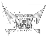
- the drawing shows the bell body of the rotary atomizer and schematically a steering air ring mounted on the rotary atomizer.
- the bell body 1 serves to spray coating material such as water-soluble or other colored lacquer, which flows over the overflow surface 2 to the spray edge 3, and is screwed with its hub part 4 in a known manner into the open end of a (not shown) hollow shaft of the drive motor of the rotary atomizer.
- This fastening construction enables a small, compact and light bell unit and a relatively short paint tube 7, around which the bell body 1 rotates.
- the coating material to be sprayed is passed into the bell body through the front end of the paint tube 7, which is arranged as a nozzle and coaxial with the axis of rotation. In the event of a color change, a washing-up liquid usually flows through the color channel of the color tube 7 instead.
- the paint tube 7 is part of a stationary tube body 8 through which additional axial bores 9 lead eccentrically parallel to the paint tube. Through these axial bores 9 outside the paint tube 7, the interior of the bell unit can be rinsed without using the paint tube 7 and e.g. Loss of color or larger amounts of detergent have to be accepted. This can be useful if regular cleaning is required not only when changing colors, but for other reasons.
- the paint tube 7 and the bores 9 open into the interior of an annular body 13 fastened to the deflection part 10, with which the deflection part is removably inserted into the bell body 1.
- the deflecting part 10 divides the coating material to be atomized into partial flows, of which one partial flow flows on the rear side of the deflecting part to the overflow surface 2, while the other partial flow reaches the front side of the deflecting part through a central opening and from there to the overflow surface 2.
- the bores 9 opening axially parallel in the ring body 13 of the deflection part 10 are fed by a flushing agent channel 9 'which is separate from the paint channel of the paint tube 7 in a radially widened part 8' of the tube body 8.
- a flushing agent channel 9 ' which is separate from the paint channel of the paint tube 7 in a radially widened part 8' of the tube body 8.
- an annular space 29 is formed which surrounds the tubular construction and is enlarged at its radially outer end into the inner wall of the bell body and trough-like at this point can be axially expanded.
- In this area on the outer circumference of the annular space 29 one or more connecting channels 20 open which connect the annular space 29 to the detergent channel 9 '.
- the one or more connecting channels 20 extend radially outwards from the detergent channel 9 'and / or as shown in the illustration incline forwards against the radial direction.
- the outer circumference of the bell body 1 is formed by a forwardly diverging, in the example considered steplessly conical outer surface 5 which extends between the spray edge 3 and a rear collar-like edge 6 facing away from the spray edge 3.
- a cross section for example, approximately U-shaped, axially open to the rear, that is to say part of the outer surface of the bell body forming annular space 15.
- outer rinsing channels 18 which are distributed at uniform angular intervals around the rotational axis and radially outward from the circumference of the annular space 29 and inclined forwardly against the axial direction through the hub part 4 of the bell body 1 to lead.
- the solvent or rinsing agent to be used can be removed from the rinsing agent channel 9 'of the central tube construction.
- the annular space 29 (on its outer circumference) has a larger diameter than that between the hub part 4 and the fixed one Pipe construction formed gap 25. This can prevent the washing liquid, which collects by centrifugal force on the outer circumference of the annular space 29, exits the bell body through the gap 25 and reaches, for example, rear bearings.
- a dynamic seal 26 which prevents the detergent from escaping can also be provided in the gap 25.
- the annular space 15 can also have a different shape, for example with an outer side wall that is inclined or curved radially outward.
- the shape of the annular space 15 can depend in particular on the number of external flushing channels 18 present. If only a single or only a few external rinsing channels are provided to simplify the design, it may be expedient, e.g. in the radially outer wall of the annular space 15 to form a relatively small annular collecting trough near its bottom (not shown) or to move the lower edge (at 6) radially inward for the detergent collection.
- a ring part 30 is expediently mounted on the rotary atomizer behind the rotating bell body 1 in the radially outer region and contains axially opening air nozzles 31 distributed around the circumference and connected to a compressed air source, which act on the flushing or solvent flowing through the outer surface 5 with steering air.
- these axial air nozzles have a radial distance from the axis of rotation which is approximately equal to half the diameter of the conical outer surface 5 in the vicinity of its rear end and thus is only slightly larger than half the diameter of the edge 6.
- a plurality of air nozzle rings with different diameters and / or outlet directions can also be provided.
- cleaning of the outer surface can also be achieved without the steering air effect described, since the solvent flowing over the edge 6 already adheres to the outer surface 5 due to the natural adhesive effect.
- This adhesive effect can be determined more clearly the larger the radius of curvature is selected at the edge 6.
- the degree of tapering of the conical outer surface 5 also influences how well the solvent is applied.
- the flushing agent or solvent does not necessarily have to be branched off from the central tube construction, but it can also be in another way into the interior of the bell body or to a location lying radially inside the outer surface to be cleaned or, if present, in an area corresponding to the annular space 15 Space or a corresponding axial depression are guided and flow from there in a laminar manner to the lateral outer surface on the bell circumference.
- a separate control valve can be provided with which the external rinsing process can be controlled separately.
Landscapes
- Nozzles (AREA)
- Vaporization, Distillation, Condensation, Sublimation, And Cold Traps (AREA)
- Details Or Accessories Of Spraying Plant Or Apparatus (AREA)
- Cleaning Or Drying Semiconductors (AREA)
Applications Claiming Priority (2)
| Application Number | Priority Date | Filing Date | Title |
|---|---|---|---|
| DE9419641U DE9419641U1 (de) | 1994-12-07 | 1994-12-07 | Rotationszerstäuber mit einem Glockenkörper |
| DE9419641U | 1994-12-07 |
Publications (3)
| Publication Number | Publication Date |
|---|---|
| EP0715896A2 true EP0715896A2 (fr) | 1996-06-12 |
| EP0715896A3 EP0715896A3 (fr) | 1997-04-23 |
| EP0715896B1 EP0715896B1 (fr) | 2001-04-04 |
Family
ID=6917120
Family Applications (1)
| Application Number | Title | Priority Date | Filing Date |
|---|---|---|---|
| EP95119236A Expired - Lifetime EP0715896B1 (fr) | 1994-12-07 | 1995-12-06 | Atomatiseur rotatif à cloche |
Country Status (10)
| Country | Link |
|---|---|
| US (1) | US5707009A (fr) |
| EP (1) | EP0715896B1 (fr) |
| JP (1) | JP3940445B2 (fr) |
| KR (1) | KR100384649B1 (fr) |
| AU (1) | AU4022995A (fr) |
| BR (1) | BR9505688A (fr) |
| CA (1) | CA2164564C (fr) |
| CZ (1) | CZ286837B6 (fr) |
| DE (2) | DE9419641U1 (fr) |
| ES (1) | ES2088776T3 (fr) |
Cited By (10)
| Publication number | Priority date | Publication date | Assignee | Title |
|---|---|---|---|---|
| DE19636159A1 (de) * | 1996-09-06 | 1998-03-12 | Abb Patent Gmbh | Rotationszerstäuber |
| US6050499A (en) * | 1996-12-03 | 2000-04-18 | Abb K. K. | Rotary spray head coater |
| EP0864367A4 (fr) * | 1996-10-01 | 2000-06-28 | Abb Kk | Tete de pulverisation rotative |
| WO2011018169A1 (fr) | 2009-08-14 | 2011-02-17 | Dürr Systems GmbH | Buse à peinture pour une cloche d'un pulvérisateur rotatif |
| WO2011035887A1 (fr) | 2009-09-24 | 2011-03-31 | Dürr Systems GmbH | Pulvérisateur rotatif et procédé de contrôle de son corps de pulvérisation |
| EP2529844A1 (fr) | 2004-12-21 | 2012-12-05 | Dürr Systems GmbH | Pulvérisateur rotatif avec corps de pulvérisation |
| US9126211B2 (en) | 2009-07-24 | 2015-09-08 | Durr Systems Gmbh | Rotary atomizer comprising an atomizer bell and a retainer |
| DE19938093B4 (de) * | 1999-08-12 | 2018-02-08 | Dürr Systems Ag | Verfahren und Rotationszerstäuber zum serienweisen Beschichten von Werkstücken |
| FR3087680A1 (fr) | 2018-10-30 | 2020-05-01 | Exel Industries | Bol de pulverisation de produit de revetement, projecteur rotatif incluant un tel bol et procede de nettoyage d'un tel projecteur |
| DE102021127163A1 (de) | 2021-10-20 | 2023-04-20 | Dürr Systems Ag | Glockenteller und Rotationszerstäuber mit einem solchen Glockenteller |
Families Citing this family (31)
| Publication number | Priority date | Publication date | Assignee | Title |
|---|---|---|---|---|
| JP2809170B2 (ja) * | 1996-01-19 | 1998-10-08 | トヨタ自動車株式会社 | 回転霧化静電塗装装置 |
| US8141797B2 (en) * | 2001-01-25 | 2012-03-27 | Durr Systems Inc. | Rotary atomizer for particulate paints |
| US6189804B1 (en) * | 1998-03-27 | 2001-02-20 | Behr Systems, Inc. | Rotary atomizer for particulate paints |
| WO2000053333A1 (fr) * | 1999-03-11 | 2000-09-14 | Apv Nordic A/S, Anhydro | Atomiseur centrifuge |
| US6578779B2 (en) | 2000-10-18 | 2003-06-17 | Behr Systems, Inc. | Rotary atomizer with bell element |
| US6341734B1 (en) | 2000-10-19 | 2002-01-29 | Efc Systems, Inc. | Rotary atomizer and bell cup and methods thereof |
| DE10101372A1 (de) | 2001-01-13 | 2002-08-01 | Itw Oberflaechentechnik Gmbh | Sprühverfahren und Sprühvorrichtung für Beschichtungsflüssigkeit |
| DE10101369A1 (de) * | 2001-01-13 | 2002-07-18 | Itw Oberflaechentechnik Gmbh | Sprühverfahren und Sprühvorrichtung für Beschichtungsflüssigkeit |
| DE10101367A1 (de) * | 2001-01-13 | 2002-08-01 | Itw Oberflaechentechnik Gmbh | Sprühverfahren und Sprühvorrichtung für Beschichtungsflüssigkeit |
| FR2836638B1 (fr) * | 2002-03-01 | 2004-12-10 | Sames Technologies | Dispositif de pulverisation de produit de revetement liquide |
| US20050040257A1 (en) * | 2003-08-19 | 2005-02-24 | Seitz David M. | Atomizer with dedicated cleaning fluid system |
| US7134611B2 (en) * | 2004-05-25 | 2006-11-14 | Sunmatch Industrial Co., Ltd. | Air nozzle for pneumatic tools |
| US7967552B2 (en) * | 2004-09-03 | 2011-06-28 | Neil Edward Brett | Drive spindles |
| DE102005015604B4 (de) * | 2005-04-05 | 2007-04-12 | Dürr Systems GmbH | Rotationszerstäuberbauteil |
| DE102005044154B4 (de) | 2005-09-15 | 2007-09-27 | Dürr Systems GmbH | Rotationszerstäuberbauteil |
| US20060219816A1 (en) | 2005-04-05 | 2006-10-05 | Durr Systems | Rotary atomizer component |
| FR2887472B1 (fr) | 2005-06-23 | 2007-09-28 | Sames Technologies Soc Par Act | Bol de pulverisation, dispositif de projection equipe d'un tel bol, installation comprenant un tel dispositif et procede de montage d'un tel bol |
| JP2007007507A (ja) * | 2005-06-28 | 2007-01-18 | Trinity Ind Corp | 塗装機とその回転霧化頭 |
| JP4750803B2 (ja) * | 2006-01-19 | 2011-08-17 | Abb株式会社 | 回転霧化頭型塗装装置 |
| US20080047591A1 (en) * | 2006-08-25 | 2008-02-28 | Seitz David M | Bell cup cleaning system and method |
| DE102007004156A1 (de) | 2007-01-22 | 2008-07-24 | Rüter, Rudi | Glocke für einen Rotationszerstäuber |
| US8662416B2 (en) * | 2007-05-02 | 2014-03-04 | Ransburg Industrial Finishing K.K. | Rotary atomizer |
| US8602326B2 (en) * | 2007-07-03 | 2013-12-10 | David M. Seitz | Spray device having a parabolic flow surface |
| DE202009004682U1 (de) | 2009-04-07 | 2009-10-01 | Rüter, Rudi | Glockenanordnung für einen Rotationszerstäuber |
| DE102009051254A1 (de) | 2009-10-29 | 2010-06-17 | Daimler Ag | Rotationszerstäuber mit Lackablauf-Hemmvorrichtung |
| DE102009052656A1 (de) | 2009-11-11 | 2011-05-12 | Dürr Systems GmbH | Applikationsvorrichtung zum Applizieren und Bestrahlen eines durch Strahlung härtbaren Beschichtungsmittels |
| US9022361B2 (en) | 2012-01-05 | 2015-05-05 | Ledebuhr Industries, Inc. | Rotary atomizer drip control method and apparatus |
| US9433963B2 (en) * | 2012-11-06 | 2016-09-06 | Precision Valve & Automation, Inc. | Adhesive dispensing assembly having a mechanism for cleaning the dispensing nozzle |
| US8851397B1 (en) | 2013-11-14 | 2014-10-07 | Efc Systems, Inc. | Bell cup atomizer having improved cleaning capability |
| CN106457278B (zh) * | 2015-04-08 | 2019-02-15 | Abb株式会社 | 旋转雾化头型涂装机 |
| DE102018129964B4 (de) * | 2018-11-27 | 2023-11-16 | Dürr Systems Ag | Rotationszerstäuber und dessen Betriebsverfahren sowie Beschichtungsroboter mit Rotationszerstäuber |
Citations (3)
| Publication number | Priority date | Publication date | Assignee | Title |
|---|---|---|---|---|
| DE8607841U1 (de) | 1986-03-21 | 1986-05-15 | Behr-Industrieanlagen GmbH & Co, 7121 Ingersheim | Vorrichtung zum Vernebeln flüssiger Farbe, insbesondere Lackzerstäuber |
| DE9319555U1 (de) | 1992-12-21 | 1994-04-07 | Dürr GmbH, 70435 Stuttgart | Rotationszerstäuber mit einem Glockenkörper |
| DE4306799A1 (de) | 1993-03-04 | 1994-09-08 | Duerr Gmbh & Co | Rotationszerstäuber für eine Beschichtungsvorrichtung |
Family Cites Families (13)
| Publication number | Priority date | Publication date | Assignee | Title |
|---|---|---|---|---|
| US3224680A (en) * | 1964-06-11 | 1965-12-21 | Ford Motor Co | Atomizing apparatus having a liquid accumulation cavity |
| US4275838A (en) * | 1977-09-12 | 1981-06-30 | Ransburg Corporation | Rotating atomizing device |
| US4380321A (en) * | 1981-01-26 | 1983-04-19 | Binks Manufacturing Company | Color change valve structure for rotary head electrostatic spray coating systems |
| DE3135721C3 (de) * | 1981-09-09 | 1991-04-18 | Ransburg Gmbh | Verfahren und anlage zum verspruehen von farben |
| DE8224329U1 (de) * | 1982-08-28 | 1983-01-05 | Hermann Behr & Sohn Gmbh & Co, 7121 Ingersheim | Einrichtung zum vernebeln fluessiger farbe |
| JPH0121011Y2 (fr) * | 1984-12-13 | 1989-06-23 | ||
| DE8708312U1 (de) * | 1987-06-12 | 1987-07-30 | Behr Industrieanlagen GmbH & Co, 74379 Ingersheim | Einrichtung zum Vernebeln flüssiger Farbe |
| DE3912700C1 (en) * | 1989-04-18 | 1990-10-11 | Ransburg-Gema Gmbh, 6056 Heusenstamm, De | Rotary spray coater - has atomiser ring with solvent channels, and includes annular air inlets |
| FR2652518B1 (fr) * | 1989-10-03 | 1994-04-08 | Sames Sa | Dispositif de projection de produit de revetement a organe rotatif de pulverisation. |
| FR2661115B1 (fr) * | 1990-04-24 | 1992-07-31 | Sames Sa | Dispositif de pulverisation centrifuge d'un produit de revetement, notamment pour application par projection electrostatique. |
| DE4201379A1 (de) * | 1992-01-20 | 1993-07-22 | Baral Karl Heinz | Reinigungseinrichtung zur reinigung von duesenbohrungen |
| FR2692501B1 (fr) * | 1992-06-22 | 1995-08-04 | Sames Sa | Dispositif de projection electrostatique de produit de revetement liquide a tete de pulverisation rotative. |
| JP2830683B2 (ja) * | 1992-09-11 | 1998-12-02 | トヨタ自動車株式会社 | 回転霧化静電塗装装置 |
-
1994
- 1994-12-07 DE DE9419641U patent/DE9419641U1/de not_active Expired - Lifetime
-
1995
- 1995-11-22 CZ CZ19953082A patent/CZ286837B6/cs not_active IP Right Cessation
- 1995-11-22 US US08/561,714 patent/US5707009A/en not_active Expired - Lifetime
- 1995-12-04 KR KR1019950046297A patent/KR100384649B1/ko not_active Expired - Lifetime
- 1995-12-04 AU AU40229/95A patent/AU4022995A/en not_active Abandoned
- 1995-12-06 BR BR9505688A patent/BR9505688A/pt not_active IP Right Cessation
- 1995-12-06 CA CA2164564A patent/CA2164564C/fr not_active Expired - Lifetime
- 1995-12-06 ES ES95119236T patent/ES2088776T3/es not_active Expired - Lifetime
- 1995-12-06 EP EP95119236A patent/EP0715896B1/fr not_active Expired - Lifetime
- 1995-12-06 DE DE59509156T patent/DE59509156D1/de not_active Expired - Lifetime
- 1995-12-07 JP JP34583495A patent/JP3940445B2/ja not_active Expired - Lifetime
Patent Citations (3)
| Publication number | Priority date | Publication date | Assignee | Title |
|---|---|---|---|---|
| DE8607841U1 (de) | 1986-03-21 | 1986-05-15 | Behr-Industrieanlagen GmbH & Co, 7121 Ingersheim | Vorrichtung zum Vernebeln flüssiger Farbe, insbesondere Lackzerstäuber |
| DE9319555U1 (de) | 1992-12-21 | 1994-04-07 | Dürr GmbH, 70435 Stuttgart | Rotationszerstäuber mit einem Glockenkörper |
| DE4306799A1 (de) | 1993-03-04 | 1994-09-08 | Duerr Gmbh & Co | Rotationszerstäuber für eine Beschichtungsvorrichtung |
Cited By (20)
| Publication number | Priority date | Publication date | Assignee | Title |
|---|---|---|---|---|
| DE19636159A1 (de) * | 1996-09-06 | 1998-03-12 | Abb Patent Gmbh | Rotationszerstäuber |
| EP0864367A4 (fr) * | 1996-10-01 | 2000-06-28 | Abb Kk | Tete de pulverisation rotative |
| US6050499A (en) * | 1996-12-03 | 2000-04-18 | Abb K. K. | Rotary spray head coater |
| DE19938093B4 (de) * | 1999-08-12 | 2018-02-08 | Dürr Systems Ag | Verfahren und Rotationszerstäuber zum serienweisen Beschichten von Werkstücken |
| EP2529844A1 (fr) | 2004-12-21 | 2012-12-05 | Dürr Systems GmbH | Pulvérisateur rotatif avec corps de pulvérisation |
| US9126211B2 (en) | 2009-07-24 | 2015-09-08 | Durr Systems Gmbh | Rotary atomizer comprising an atomizer bell and a retainer |
| CN102574136B (zh) * | 2009-08-14 | 2015-10-07 | 杜尔系统有限责任公司 | 用于旋转喷雾器的钟形盘的涂料喷嘴 |
| WO2011018169A1 (fr) | 2009-08-14 | 2011-02-17 | Dürr Systems GmbH | Buse à peinture pour une cloche d'un pulvérisateur rotatif |
| DE102009037604A1 (de) | 2009-08-14 | 2011-02-24 | Dürr Systems GmbH | Farbdüse für einen Glockenteller eines Rotationszerstäubers |
| CN102574136A (zh) * | 2009-08-14 | 2012-07-11 | 杜尔系统有限责任公司 | 用于旋转喷雾器的钟形盘的涂料喷嘴 |
| US9126217B2 (en) | 2009-08-14 | 2015-09-08 | Durr Systems Gmbh | Ink jet for a bell plate of a rotary atomizer |
| WO2011035887A1 (fr) | 2009-09-24 | 2011-03-31 | Dürr Systems GmbH | Pulvérisateur rotatif et procédé de contrôle de son corps de pulvérisation |
| US9180469B2 (en) | 2009-09-24 | 2015-11-10 | Durr Systems Gmbh | Rotary atomizer and method for the control of the spraying body of said rotary atomizer |
| DE102009042956A1 (de) | 2009-09-24 | 2011-04-07 | Dürr Systems GmbH | Rotationszerstäuber und Verfahren zur Kontrolle seines Absprühkörpers |
| FR3087680A1 (fr) | 2018-10-30 | 2020-05-01 | Exel Industries | Bol de pulverisation de produit de revetement, projecteur rotatif incluant un tel bol et procede de nettoyage d'un tel projecteur |
| WO2020089242A1 (fr) | 2018-10-30 | 2020-05-07 | Exel Industries | Bol de pulvérisation de produit de revêtement, projecteur rotatif incluant un tel bol et procédé de nettoyage d'un tel projecteur |
| US11998940B2 (en) | 2018-10-30 | 2024-06-04 | Exel Industries | Bowl for spraying a coating product, rotary spraying apparatus including such a bowl, and method for cleaning such a spraying apparatus |
| DE102021127163A1 (de) | 2021-10-20 | 2023-04-20 | Dürr Systems Ag | Glockenteller und Rotationszerstäuber mit einem solchen Glockenteller |
| WO2023066673A1 (fr) | 2021-10-20 | 2023-04-27 | Dürr Systems Ag | Projecteur rotatif et pulvérisateur centrifuge équipé d'un tel projecteur rotatif |
| WO2023066996A1 (fr) | 2021-10-20 | 2023-04-27 | Dürr Systems Ag | Projecteur rotatif et pulvérisateur centrifuge équipé d'un tel projecteur rotatif |
Also Published As
| Publication number | Publication date |
|---|---|
| KR960021162A (ko) | 1996-07-18 |
| CA2164564C (fr) | 2010-03-16 |
| EP0715896B1 (fr) | 2001-04-04 |
| CA2164564A1 (fr) | 1996-06-08 |
| KR100384649B1 (ko) | 2003-08-21 |
| ES2088776T1 (es) | 1996-09-16 |
| US5707009A (en) | 1998-01-13 |
| EP0715896A3 (fr) | 1997-04-23 |
| CZ286837B6 (en) | 2000-07-12 |
| DE59509156D1 (de) | 2001-05-10 |
| CZ308295A3 (en) | 1997-09-17 |
| JP3940445B2 (ja) | 2007-07-04 |
| JPH08332415A (ja) | 1996-12-17 |
| AU4022995A (en) | 1996-06-13 |
| ES2088776T3 (es) | 2001-08-16 |
| BR9505688A (pt) | 1997-11-11 |
| MX9505093A (es) | 1998-10-31 |
| DE9419641U1 (de) | 1995-02-02 |
Similar Documents
| Publication | Publication Date | Title |
|---|---|---|
| EP0715896B1 (fr) | Atomatiseur rotatif à cloche | |
| DE4330602C2 (de) | Drehzerstäubervorrichtung | |
| EP0032391B1 (fr) | Dispositif de pulvérisation de peinture liquide | |
| DE69306975T2 (de) | Farbspritzvorrichtung mit rotierendem zerstäubungselement und werkzeug zum montieren und demontieren dieses elements | |
| DE69722155T2 (de) | Farbspritzvorrichtung | |
| EP2643096B1 (fr) | Dispositif de nettoyage et brosse de nettoyage et méthode de nettoyage correspondante | |
| DE69717416T2 (de) | Rotationszerstäubungskopf | |
| DE69104761T2 (de) | Rotationszerstäuber mit integrierter Farbwechselvorrichtung und Fluiddruckregler. | |
| EP2099570A1 (fr) | Anneau pour guider l'air comprenant une cavité annulaire et cloche correspondante | |
| EP0104394B1 (fr) | Appareil pour la pulvérisation de la peinture liquide | |
| DE3912700C1 (en) | Rotary spray coater - has atomiser ring with solvent channels, and includes annular air inlets | |
| EP1242190B1 (fr) | Atomiseur rotatif a grande vitesse pour application de peinture en poudre | |
| WO2020108930A1 (fr) | Pulvérisateur rotatif | |
| DE8607841U1 (de) | Vorrichtung zum Vernebeln flüssiger Farbe, insbesondere Lackzerstäuber | |
| EP3890894B1 (fr) | Dispositif de collecte de fluide de nettoyage de pulvérisateur | |
| DE3720200A1 (de) | Spruehbeschichtungseinrichtung mit einem rotationsspruehorgan | |
| EP1685909B1 (fr) | Pulvérisateur rotatif pour économiser l'agent de rinçage | |
| DE3505619C2 (de) | Verfahren zum Beschichten von Gegenständen und Vorrichtung zur Durchführung des Verfahrens | |
| DE19517477A1 (de) | Rotationszerstaueber | |
| EP0827781B1 (fr) | Pulvérisateur rotatif | |
| DE3816417C2 (fr) | ||
| DE19938093A1 (de) | Verfahren und Rotationszerstäuber zum serienweisen Beschichten von Werkstücken | |
| EP1452235B1 (fr) | Bol de pulvérisation et pulvérisateur rotatif | |
| EP0625377B1 (fr) | Tête de pulvérisation pour la projection de peintures liquides | |
| DE19831887A1 (de) | Spritzvorrichtung |
Legal Events
| Date | Code | Title | Description |
|---|---|---|---|
| PUAI | Public reference made under article 153(3) epc to a published international application that has entered the european phase |
Free format text: ORIGINAL CODE: 0009012 |
|
| AK | Designated contracting states |
Kind code of ref document: A2 Designated state(s): BE DE ES FR GB IT NL SE |
|
| REG | Reference to a national code |
Ref country code: ES Ref legal event code: BA2A Ref document number: 2088776 Country of ref document: ES Kind code of ref document: T1 |
|
| GBC | Gb: translation of claims filed (gb section 78(7)/1977) | ||
| TCNL | Nl: translation of patent claims filed | ||
| EL | Fr: translation of claims filed | ||
| REG | Reference to a national code |
Ref country code: ES Ref legal event code: BA2A Ref document number: 2088776 Country of ref document: ES Kind code of ref document: T1 |
|
| PUAL | Search report despatched |
Free format text: ORIGINAL CODE: 0009013 |
|
| AK | Designated contracting states |
Kind code of ref document: A3 Designated state(s): BE DE ES FR GB IT NL SE |
|
| 17P | Request for examination filed |
Effective date: 19970429 |
|
| RAP1 | Party data changed (applicant data changed or rights of an application transferred) |
Owner name: DUERR SYSTEMS GMBH |
|
| 17Q | First examination report despatched |
Effective date: 19990720 |
|
| GRAG | Despatch of communication of intention to grant |
Free format text: ORIGINAL CODE: EPIDOS AGRA |
|
| GRAG | Despatch of communication of intention to grant |
Free format text: ORIGINAL CODE: EPIDOS AGRA |
|
| GRAH | Despatch of communication of intention to grant a patent |
Free format text: ORIGINAL CODE: EPIDOS IGRA |
|
| GRAH | Despatch of communication of intention to grant a patent |
Free format text: ORIGINAL CODE: EPIDOS IGRA |
|
| GRAA | (expected) grant |
Free format text: ORIGINAL CODE: 0009210 |
|
| AK | Designated contracting states |
Kind code of ref document: B1 Designated state(s): BE DE ES FR GB IT NL SE |
|
| GBT | Gb: translation of ep patent filed (gb section 77(6)(a)/1977) |
Effective date: 20010404 |
|
| ITF | It: translation for a ep patent filed | ||
| REF | Corresponds to: |
Ref document number: 59509156 Country of ref document: DE Date of ref document: 20010510 |
|
| ET | Fr: translation filed | ||
| REG | Reference to a national code |
Ref country code: ES Ref legal event code: FG2A Ref document number: 2088776 Country of ref document: ES Kind code of ref document: T3 |
|
| REG | Reference to a national code |
Ref country code: GB Ref legal event code: IF02 |
|
| PLBE | No opposition filed within time limit |
Free format text: ORIGINAL CODE: 0009261 |
|
| STAA | Information on the status of an ep patent application or granted ep patent |
Free format text: STATUS: NO OPPOSITION FILED WITHIN TIME LIMIT |
|
| 26N | No opposition filed | ||
| PGFP | Annual fee paid to national office [announced via postgrant information from national office to epo] |
Ref country code: ES Payment date: 20141226 Year of fee payment: 20 Ref country code: SE Payment date: 20141219 Year of fee payment: 20 Ref country code: GB Payment date: 20141219 Year of fee payment: 20 Ref country code: DE Payment date: 20141211 Year of fee payment: 20 |
|
| PGFP | Annual fee paid to national office [announced via postgrant information from national office to epo] |
Ref country code: NL Payment date: 20141219 Year of fee payment: 20 Ref country code: FR Payment date: 20141219 Year of fee payment: 20 |
|
| PGFP | Annual fee paid to national office [announced via postgrant information from national office to epo] |
Ref country code: IT Payment date: 20141222 Year of fee payment: 20 |
|
| PGFP | Annual fee paid to national office [announced via postgrant information from national office to epo] |
Ref country code: BE Payment date: 20141219 Year of fee payment: 20 |
|
| REG | Reference to a national code |
Ref country code: DE Ref legal event code: R071 Ref document number: 59509156 Country of ref document: DE |
|
| REG | Reference to a national code |
Ref country code: NL Ref legal event code: MK Effective date: 20151205 |
|
| REG | Reference to a national code |
Ref country code: GB Ref legal event code: PE20 Expiry date: 20151205 |
|
| PG25 | Lapsed in a contracting state [announced via postgrant information from national office to epo] |
Ref country code: GB Free format text: LAPSE BECAUSE OF EXPIRATION OF PROTECTION Effective date: 20151205 |
|
| REG | Reference to a national code |
Ref country code: SE Ref legal event code: EUG |
|
| REG | Reference to a national code |
Ref country code: ES Ref legal event code: FD2A Effective date: 20160329 |
|
| PG25 | Lapsed in a contracting state [announced via postgrant information from national office to epo] |
Ref country code: ES Free format text: LAPSE BECAUSE OF EXPIRATION OF PROTECTION Effective date: 20151207 |