EP0715902A1 - Procédé et installation pour la séparation thermique de polluants d'une matière contaminée - Google Patents
Procédé et installation pour la séparation thermique de polluants d'une matière contaminée Download PDFInfo
- Publication number
- EP0715902A1 EP0715902A1 EP94116974A EP94116974A EP0715902A1 EP 0715902 A1 EP0715902 A1 EP 0715902A1 EP 94116974 A EP94116974 A EP 94116974A EP 94116974 A EP94116974 A EP 94116974A EP 0715902 A1 EP0715902 A1 EP 0715902A1
- Authority
- EP
- European Patent Office
- Prior art keywords
- steam
- treated
- treatment
- unit
- conveyor belt
- Prior art date
- Legal status (The legal status is an assumption and is not a legal conclusion. Google has not performed a legal analysis and makes no representation as to the accuracy of the status listed.)
- Withdrawn
Links
Images


Classifications
-
- C—CHEMISTRY; METALLURGY
- C02—TREATMENT OF WATER, WASTE WATER, SEWAGE, OR SLUDGE
- C02F—TREATMENT OF WATER, WASTE WATER, SEWAGE, OR SLUDGE
- C02F1/00—Treatment of water, waste water, or sewage
- C02F1/44—Treatment of water, waste water, or sewage by dialysis, osmosis or reverse osmosis
-
- B—PERFORMING OPERATIONS; TRANSPORTING
- B09—DISPOSAL OF SOLID WASTE; RECLAMATION OF CONTAMINATED SOIL
- B09B—DISPOSAL OF SOLID WASTE NOT OTHERWISE PROVIDED FOR
- B09B3/00—Destroying solid waste or transforming solid waste into something useful or harmless
- B09B3/30—Destroying solid waste or transforming solid waste into something useful or harmless involving mechanical treatment
- B09B3/35—Shredding, crushing or cutting
-
- B—PERFORMING OPERATIONS; TRANSPORTING
- B09—DISPOSAL OF SOLID WASTE; RECLAMATION OF CONTAMINATED SOIL
- B09C—RECLAMATION OF CONTAMINATED SOIL
- B09C1/00—Reclamation of contaminated soil
- B09C1/06—Reclamation of contaminated soil thermally
-
- C—CHEMISTRY; METALLURGY
- C02—TREATMENT OF WATER, WASTE WATER, SEWAGE, OR SLUDGE
- C02F—TREATMENT OF WATER, WASTE WATER, SEWAGE, OR SLUDGE
- C02F1/00—Treatment of water, waste water, or sewage
- C02F1/44—Treatment of water, waste water, or sewage by dialysis, osmosis or reverse osmosis
- C02F1/441—Treatment of water, waste water, or sewage by dialysis, osmosis or reverse osmosis by reverse osmosis
-
- C—CHEMISTRY; METALLURGY
- C02—TREATMENT OF WATER, WASTE WATER, SEWAGE, OR SLUDGE
- C02F—TREATMENT OF WATER, WASTE WATER, SEWAGE, OR SLUDGE
- C02F1/00—Treatment of water, waste water, or sewage
- C02F1/44—Treatment of water, waste water, or sewage by dialysis, osmosis or reverse osmosis
- C02F1/444—Treatment of water, waste water, or sewage by dialysis, osmosis or reverse osmosis by ultrafiltration or microfiltration
-
- C—CHEMISTRY; METALLURGY
- C02—TREATMENT OF WATER, WASTE WATER, SEWAGE, OR SLUDGE
- C02F—TREATMENT OF WATER, WASTE WATER, SEWAGE, OR SLUDGE
- C02F1/00—Treatment of water, waste water, or sewage
- C02F1/44—Treatment of water, waste water, or sewage by dialysis, osmosis or reverse osmosis
- C02F1/447—Treatment of water, waste water, or sewage by dialysis, osmosis or reverse osmosis by membrane distillation
Definitions
- the invention relates to a process for the thermal separation of organic and / or inorganic pollutants from contaminated material to be treated, such as soils, sludges, mill scale and the like, with hot gases, which are then dedusted, condensed and subjected to condensate cleaning. Furthermore, the invention relates to a plant for performing the method.
- the known method does not allow continuous operation, since the furnace has to be loaded with the material to be treated and emptied later.
- complex equipment such as chain scraper conveyors are required.
- the return of 80 to 90% of the water vapor-containing contaminated treatment gases into the furnace causes high corrosion risks due to the introduced steam-air / pollutant mixture, which represents an aggressive furnace atmosphere.
- the invention is based on the object of improving a process for the thermal separation of organic and / or inorganic pollutants from contaminated material to be treated in such a way that, in the context of a continuous process without an oven, avoiding a high excess of air, all organic and inorganic contaminations Nature can be removed from the material to be treated in an economical manner.
- the object is achieved according to the invention in that the material to be treated is spread over a gas-permeable substrate continuously or stepwise forward from a feed zone to a removal zone in a predetermined layer thickness, such that only superheated steam at a temperature of ⁇ 700 ° C.
- the heat content of the superheated steam is initially exploited in the continuous process to dry the material to be treated in the application zone of the reaction chamber, and the now dry material to be treated is heated by the superheated steam at a temperature of ⁇ 700 ° C. in order to avoid the contamination to evaporate.
- the boiling points are approximately between 400 ° C. and 500 ° C., as is also the case with inorganic pollutants, such as mercury, chlorine, fluorine and sulfur, in dissolved form or crystalline form. Even easily releasable cyanides can be evaporated by the hot steam treatment. A separate heating is not necessary.
- the treatment is preferably carried out with superheated steam at 700 ° C. and a pressure of 1.5 bar, the layer thickness advantageously being set to between 200 mm and 500 mm.
- the treated goods are freed from pollutants, for example a clean floor.
- the hot vapor vapors now contaminated are removed, dedusted and condensed in a manner known per se, the dust obtained advantageously being returned to the process in front of the feed zone, possibly after granulating, pelleting or coagulating.
- the condensate from the condensation is preferably processed in a three-phase separator, the aqueous phase being used as boiler feed water for the production of superheated steam.
- the vacuum air generated during the condensation is fed to an adsorber, wherein activated carbon can advantageously be used for the adsorption.
- activated carbon can advantageously be used for the adsorption.
- Pollutants such as chlorine and sulfur are removed from the air, so that a considerable part of the air can be fed to the burner of the boiler system as combustion air.
- the material to be treated which has been cleaned by thermal treatment, subsequently be subjected to post-treatment by means of process media in a reactor column.
- the reactor column can be operated in a parallel steam cycle.
- the method according to the invention can be carried out with little economic outlay and a high quality of the pollutant separation is achieved by thermal means.
- the high quality of cleaning with the simple steam flow method through the moving layer of the material to be treated is surprising. Compared to conventional methods, good mixing of the material to be treated and steam is achieved and the individual contaminants can be separated in a simple manner with little effort. Large quantities of exhaust air are avoided, as are complex exhaust gas purification processes.
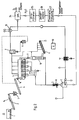
- a system which consists of a loading unit, a steaming unit, a dispensing unit for the material to be treated, a steam generator and a vapor cleaning device, the steaming unit comprising an essentially gas-tight housing with a feed lock and a discharge lock between which is arranged a gas-permeable conveyor belt for the material to be treated, under which are arranged supply nozzles for superheated steam distributed over the entire surface.
- a second conveyor belt can be arranged below the conveyor belt for the material to be treated, with the opposite direction of conveyance for collecting and discharging the very fine materials, which can again be fed to the application zone of the steaming unit by means of an elevator.
- the steaming device consists of a vapor-permeable conveyor belt 5, which is fed with material via an access lock 16.
- the layer thickness can be regulated by the feed speed of the belt 5.
- a further conveyor belt is arranged beneath the belt 5, by means of which fine material falling through the belt 5 is fed out of the steaming device to an elevator 15, by means of which the material is returned to the circuit.
- the elevator 15 conveys the fine material back onto the conveyor belt 4.
- the cleaned material is fed via an exit lock 17 to a conveyor belt 6, which in the exemplary embodiment shown is a cooling belt. Residual steam is drawn off via a steam outlet and also returned to the circuit. After the cooling belt, the cleaned goods are made available for recycling.
- boiler feed water is heated to about 145 ° C. at a pressure of preferably 1.5 bar by means of a burner which operates in a range of 1250 ° C.
- a superheater 8 steam with a temperature of preferably 700 ° C is generated, which is fed to a steam distributor at a substantially constant pressure of between 0.5 and 1.5 bar.
- the steam is introduced into the steaming system 5 via the steam distributor and is guided there into the area between the upper run and the lower run of the steam-permeable conveyor belt, covering the entire surface. This ensures that steam flows through the layer on the conveyor belt to be cleaned evenly.
- the goods are cleaned from KW, CKW, PAK, CI, S and Hg, among others.
- the vaporization is continued over a predetermined period of time. Since the steaming device, which is also referred to as a distillation reactor, is essentially gas-tight, a corresponding pressure of, for example, 1.5 bar can be maintained.
- the steam is fed from the distillation reactor via lines to a fine particle dust filter 9, in which the vapors are dedusted, for example, ⁇ 10 mg / Ncbm.
- the fine particle dust is granulated, pelleted, coagulated or the like in a mixer 11.
- a mixture with H2O can optionally be carried out with the addition of binders or other additives.
- the mixture product can then be returned to the circuit, for example on the conveyor belt 4.
- the dedusted vapors are fed to a condenser 10.
- the condensate is treated in a three-phase separator 24, in which oils and solids (sludge) and water are separated from one another.
- oils and solids can be discarded while the water after a further processing is used as boiler feed water in the boiler 7 for hot steam generation and thus remains in the circuit. It is pointed out that a purifier with a downstream clarifier can also be used instead of the three-phase separator
- a water treatment system consisting of ultrafiltration 25, reverse osmosis 26 and thermal degassing 27 is used to treat the separated water, which produces salt-free feed water in mixed bed quality.
- this means a conductivity of 0.2 ⁇ S / cm and the greatest possible freedom from silicate in the make-up water.
- the water in the boiler is salted up to 50 ⁇ S / cm, so that a conductivity of 0.2 ⁇ S / cm and a silicate content of 0.02mg / l are maintained in the steam.
- the treatment used with reverse osmosis device 26 represents an ideal method for setting the desired water quality.
- the gases drawn off from the condenser 10 by means of a vacuum pump are fed to an adsorber 12.
- this adsorber which carries out exhaust air purification using activated carbon, for example, volatile inorganic components such as sulfur, chlorides, mercury, arsenic, etc. are produced.
- the volatile organic substances After mixing with fresh air in the burner and the upstream combustion chamber on the steam boiler, the volatile organic substances are fully burned out at temperatures around 1200 ° C or 1250 ° C.
- the exemplary embodiment shown in FIG. 2 is a modified system compared to the system shown in FIG. 1.
- the same elements are provided with the same reference symbols.
- the screen 23 was omitted, so that the magnetic tape 14 in the area of the Conveyor belt 2 is formed.
- An elevator 15 was also dispensed with.
- the main difference from the exemplary embodiment shown in FIG. 1 is that the distillation reactor 5 is followed by a further reactor column 18.
- the reactor column which essentially consists of a reactor housing, in which a harmful gas pipe is arranged, further and / or post-treatment of the material to be cleaned takes place.
- Dome-like sheets are arranged around the harmful gas pipe, so that the material to be cleaned trickles over sheets to the discharge arranged below, while a material to be treated flows through it in countercurrent.
- This gas collects with the other substances extracted from the items to be cleaned, inside the hoods and is discharged via the harmful gas pipe.
- the plant shown in FIG. 2 corresponds to the plant shown in FIG. 1 in terms of the process sequence.
- a distillation reactor 5 is shown schematically.
- the distillation reactor 5 is essentially arranged in a gas-tight housing, preferably made of stainless steel.
- An input lock 16 is formed on the loading side and an output lock 17 on the discharge side.
- a distillation belt 20, which is permeable to steam, is arranged within the housing. This is, for example, a perforated stainless steel band or a metal grid.
- the steam leaves the housing upwards.
- a part of the vaporization system is shown schematically enlarged in FIG. 4. The steam is supplied from the side via a channel 21 between the upper run and lower run of the belt 20.
- the treatment time of a layer within the distillation reactor can be up to 60 minutes.
- the steam preferably has a temperature of 700 ° C at a flow pressure of 0.5 and 1.5 bar.
Landscapes
- Engineering & Computer Science (AREA)
- Environmental & Geological Engineering (AREA)
- Life Sciences & Earth Sciences (AREA)
- Hydrology & Water Resources (AREA)
- Water Supply & Treatment (AREA)
- Chemical & Material Sciences (AREA)
- Organic Chemistry (AREA)
- Physics & Mathematics (AREA)
- Thermal Sciences (AREA)
- Soil Sciences (AREA)
- Processing Of Solid Wastes (AREA)
Priority Applications (1)
| Application Number | Priority Date | Filing Date | Title |
|---|---|---|---|
| EP94116974A EP0715902A1 (fr) | 1994-10-27 | 1994-10-27 | Procédé et installation pour la séparation thermique de polluants d'une matière contaminée |
Applications Claiming Priority (1)
| Application Number | Priority Date | Filing Date | Title |
|---|---|---|---|
| EP94116974A EP0715902A1 (fr) | 1994-10-27 | 1994-10-27 | Procédé et installation pour la séparation thermique de polluants d'une matière contaminée |
Publications (1)
| Publication Number | Publication Date |
|---|---|
| EP0715902A1 true EP0715902A1 (fr) | 1996-06-12 |
Family
ID=8216414
Family Applications (1)
| Application Number | Title | Priority Date | Filing Date |
|---|---|---|---|
| EP94116974A Withdrawn EP0715902A1 (fr) | 1994-10-27 | 1994-10-27 | Procédé et installation pour la séparation thermique de polluants d'une matière contaminée |
Country Status (1)
| Country | Link |
|---|---|
| EP (1) | EP0715902A1 (fr) |
Cited By (6)
| Publication number | Priority date | Publication date | Assignee | Title |
|---|---|---|---|---|
| WO1999003609A1 (fr) * | 1997-07-18 | 1999-01-28 | Mellin, Monica | Procede permettant de separer une substance contaminante d'une matiere contaminee par cette substance |
| DE10160566B4 (de) * | 2001-02-12 | 2010-04-22 | Parsons Corp., Pasadena | Verbessertes Verfahren zur verbrennungslosen Dekontamination von Materialien, die gefährliche Bestandteile enthalten |
| US8257461B2 (en) | 2007-04-19 | 2012-09-04 | Savaterra Oy | Method of producing fertilizer out of sludge |
| DE102013211252A1 (de) | 2013-06-17 | 2014-12-31 | Robert Bosch Gmbh | Anlage und Verfahren zur Behandlung von verunreinigtem Abwasser |
| CN110986065A (zh) * | 2019-11-18 | 2020-04-10 | 国网河北省电力有限公司电力科学研究院 | 利用干渣机的冷却空气加热烟气的系统及消除烟羽的方法 |
| CN113426820A (zh) * | 2021-08-02 | 2021-09-24 | 安徽省通源环境节能股份有限公司 | 一种过热式蒸汽直接热脱附装置 |
Citations (4)
| Publication number | Priority date | Publication date | Assignee | Title |
|---|---|---|---|---|
| EP0405067A2 (fr) * | 1989-06-30 | 1991-01-02 | LEONHARD WEISS GmbH & Co. NIEDERLASSUNG CRAILSHEIM | Dispositif pour éliminer des contaminants volatils du sol ou analogue |
| EP0432812A1 (fr) * | 1989-11-15 | 1991-06-19 | METALLGESELLSCHAFT Aktiengesellschaft | Procédé de nettoyage de terres contaminées |
| EP0469443A2 (fr) * | 1990-07-30 | 1992-02-05 | HEINRICH DERNBACH GmbH, ÖKOLOGISCH-LANDSCHAFTSBEZOGENE SYSTEMBERATUNG | Procédé de traitement de déchets |
| DE4303722C1 (de) * | 1993-02-10 | 1994-05-05 | Metallgesellschaft Ag | Verfahren zur thermischen Abtrennung von organischen und/oder anorganischen Stoffen aus kontaminiertem Material |
-
1994
- 1994-10-27 EP EP94116974A patent/EP0715902A1/fr not_active Withdrawn
Patent Citations (4)
| Publication number | Priority date | Publication date | Assignee | Title |
|---|---|---|---|---|
| EP0405067A2 (fr) * | 1989-06-30 | 1991-01-02 | LEONHARD WEISS GmbH & Co. NIEDERLASSUNG CRAILSHEIM | Dispositif pour éliminer des contaminants volatils du sol ou analogue |
| EP0432812A1 (fr) * | 1989-11-15 | 1991-06-19 | METALLGESELLSCHAFT Aktiengesellschaft | Procédé de nettoyage de terres contaminées |
| EP0469443A2 (fr) * | 1990-07-30 | 1992-02-05 | HEINRICH DERNBACH GmbH, ÖKOLOGISCH-LANDSCHAFTSBEZOGENE SYSTEMBERATUNG | Procédé de traitement de déchets |
| DE4303722C1 (de) * | 1993-02-10 | 1994-05-05 | Metallgesellschaft Ag | Verfahren zur thermischen Abtrennung von organischen und/oder anorganischen Stoffen aus kontaminiertem Material |
Cited By (8)
| Publication number | Priority date | Publication date | Assignee | Title |
|---|---|---|---|---|
| WO1999003609A1 (fr) * | 1997-07-18 | 1999-01-28 | Mellin, Monica | Procede permettant de separer une substance contaminante d'une matiere contaminee par cette substance |
| DE10160566B4 (de) * | 2001-02-12 | 2010-04-22 | Parsons Corp., Pasadena | Verbessertes Verfahren zur verbrennungslosen Dekontamination von Materialien, die gefährliche Bestandteile enthalten |
| US8257461B2 (en) | 2007-04-19 | 2012-09-04 | Savaterra Oy | Method of producing fertilizer out of sludge |
| DE102013211252A1 (de) | 2013-06-17 | 2014-12-31 | Robert Bosch Gmbh | Anlage und Verfahren zur Behandlung von verunreinigtem Abwasser |
| US10112849B2 (en) | 2013-06-17 | 2018-10-30 | Robert Bosch Gmbh | System and method for treating contaminated wastewater |
| CN110986065A (zh) * | 2019-11-18 | 2020-04-10 | 国网河北省电力有限公司电力科学研究院 | 利用干渣机的冷却空气加热烟气的系统及消除烟羽的方法 |
| CN110986065B (zh) * | 2019-11-18 | 2021-08-17 | 国网河北省电力有限公司电力科学研究院 | 利用干渣机的冷却空气加热烟气的系统及消除烟羽的方法 |
| CN113426820A (zh) * | 2021-08-02 | 2021-09-24 | 安徽省通源环境节能股份有限公司 | 一种过热式蒸汽直接热脱附装置 |
Similar Documents
| Publication | Publication Date | Title |
|---|---|---|
| DE69131623T2 (de) | Verfahren zur entseuchung kontaminierten bodens | |
| DE3706684C2 (fr) | ||
| DE69704270T2 (de) | Verfahren und Vorrichtung zum Behandeln von Prozeßströmen aus einem System zum Trennen von Bestandteilen aus kontaminiertem Material | |
| EP1289893B1 (fr) | Dispositif et procede pour traiter des dechets contenant des hydrocarbures | |
| EP0432812B1 (fr) | Procédé de nettoyage de terres contaminées | |
| DE4112593A1 (de) | Verfahren und anlage zum thermischen aufbereiten von mit organischen komponenten verunreinigten abfaellen, insbesondere von metallschrott | |
| WO1990012756A1 (fr) | Procede et dispositif pour traiter des saumures ainsi que des sels mineraux ou melanges de sels mineraux contamines | |
| DE3902611C2 (de) | Verfahren und Vorrichtung zum Desodorieren und Reinigen von von der Verbrennung von nassem Abfallschlamm herrührenden nassen Abgasen bei mittelmäßiger Temperatur | |
| DE69218177T2 (de) | Methode und einrichtung zur behandlung von abgas | |
| DE3612259A1 (de) | Loesemittel-eliminationsverfahren zur reinigung von luft von loesemitteldaempfen | |
| EP0715902A1 (fr) | Procédé et installation pour la séparation thermique de polluants d'une matière contaminée | |
| EP0701491B1 (fr) | Procede et dispositif pour le nettoyage de terres polluees | |
| EP0498017B1 (fr) | Procédé d'élimination d'éléments polluants de matériaux contaminés, notamment de sols et de gravats contaminés | |
| DE3023670C2 (de) | Verfahren und Vorrichtung zum Schwelen von Ölschiefer | |
| DE19715839B4 (de) | Verfahren und Vorrichtung zur Reinigung von öl- und wasserhaltigen Walzzunderschlämmen | |
| EP0341580B1 (fr) | Procédé de purification par distillation de matériaux contenant du mercure ou bien de matériaux mixtes | |
| DE1257117B (de) | Vorrichtung zum Erzielen chemischer bzw. physikalischer Wirkungen zwischen einem schuettbaren Feststoff und wenigstens einem stroemungsfaehigen Medium | |
| WO1993018866A1 (fr) | Procede de nettoyage d'une terre contaminee | |
| DE69204420T2 (de) | Verfahren zum Entfernen von Schadstoffen aus Substrattrocknungsgas. | |
| DE69817588T2 (de) | Behandlung von verunreinigten böden | |
| DE3805435A1 (de) | Verfahren und vorrichtung zur thermischen reinigung von beschichteten werkstuecken | |
| EP0509315B1 (fr) | Procédé et dispositif pour le traitement et l'élimination de matières polluantes solides | |
| DE2715607A1 (de) | Verfahren und vorrichtung zur behandlung eines verunreinigten abgases | |
| DE3925399A1 (de) | Verfahren zum aufarbeiten von mit schwermetall beladenen aktivkohlen | |
| DE19528708A1 (de) | Verfahren zum Abtrennen von flüchtigen Bestandteilen aus Feststoffgemischen, insbesondere aus Bauschutt, Bodenmaterial und Schlämmen |
Legal Events
| Date | Code | Title | Description |
|---|---|---|---|
| PUAI | Public reference made under article 153(3) epc to a published international application that has entered the european phase |
Free format text: ORIGINAL CODE: 0009012 |
|
| 17P | Request for examination filed |
Effective date: 19950519 |
|
| AK | Designated contracting states |
Kind code of ref document: A1 Designated state(s): AT BE DE ES FR IT LU NL |
|
| STAA | Information on the status of an ep patent application or granted ep patent |
Free format text: STATUS: THE APPLICATION HAS BEEN WITHDRAWN |
|
| 18W | Application withdrawn |
Withdrawal date: 19960531 |