EP0715933B1 - Stanzmesser - Google Patents
Stanzmesser Download PDFInfo
- Publication number
- EP0715933B1 EP0715933B1 EP95117933A EP95117933A EP0715933B1 EP 0715933 B1 EP0715933 B1 EP 0715933B1 EP 95117933 A EP95117933 A EP 95117933A EP 95117933 A EP95117933 A EP 95117933A EP 0715933 B1 EP0715933 B1 EP 0715933B1
- Authority
- EP
- European Patent Office
- Prior art keywords
- cutting edge
- punching
- cutting
- punch
- knife
- Prior art date
- Legal status (The legal status is an assumption and is not a legal conclusion. Google has not performed a legal analysis and makes no representation as to the accuracy of the status listed.)
- Expired - Lifetime
Links
Images
Classifications
-
- B—PERFORMING OPERATIONS; TRANSPORTING
- B26—HAND CUTTING TOOLS; CUTTING; SEVERING
- B26D—CUTTING; DETAILS COMMON TO MACHINES FOR PERFORATING, PUNCHING, CUTTING-OUT, STAMPING-OUT OR SEVERING
- B26D1/00—Cutting through work characterised by the nature or movement of the cutting member or particular materials not otherwise provided for; Apparatus or machines therefor; Cutting members therefor
- B26D1/0006—Cutting members therefor
-
- B—PERFORMING OPERATIONS; TRANSPORTING
- B26—HAND CUTTING TOOLS; CUTTING; SEVERING
- B26F—PERFORATING; PUNCHING; CUTTING-OUT; STAMPING-OUT; SEVERING BY MEANS OTHER THAN CUTTING
- B26F1/00—Perforating; Punching; Cutting-out; Stamping-out; Apparatus therefor
- B26F1/38—Cutting-out; Stamping-out
- B26F1/44—Cutters therefor; Dies therefor
-
- B—PERFORMING OPERATIONS; TRANSPORTING
- B26—HAND CUTTING TOOLS; CUTTING; SEVERING
- B26D—CUTTING; DETAILS COMMON TO MACHINES FOR PERFORATING, PUNCHING, CUTTING-OUT, STAMPING-OUT OR SEVERING
- B26D1/00—Cutting through work characterised by the nature or movement of the cutting member or particular materials not otherwise provided for; Apparatus or machines therefor; Cutting members therefor
- B26D1/0006—Cutting members therefor
- B26D2001/0053—Cutting members therefor having a special cutting edge section or blade section
-
- B—PERFORMING OPERATIONS; TRANSPORTING
- B26—HAND CUTTING TOOLS; CUTTING; SEVERING
- B26D—CUTTING; DETAILS COMMON TO MACHINES FOR PERFORATING, PUNCHING, CUTTING-OUT, STAMPING-OUT OR SEVERING
- B26D1/00—Cutting through work characterised by the nature or movement of the cutting member or particular materials not otherwise provided for; Apparatus or machines therefor; Cutting members therefor
- B26D1/0006—Cutting members therefor
- B26D2001/0086—Cutting members therefor having a radiussed blunt cutting edge
-
- B—PERFORMING OPERATIONS; TRANSPORTING
- B26—HAND CUTTING TOOLS; CUTTING; SEVERING
- B26F—PERFORATING; PUNCHING; CUTTING-OUT; STAMPING-OUT; SEVERING BY MEANS OTHER THAN CUTTING
- B26F1/00—Perforating; Punching; Cutting-out; Stamping-out; Apparatus therefor
- B26F1/38—Cutting-out; Stamping-out
- B26F1/384—Cutting-out; Stamping-out using rotating drums
-
- B—PERFORMING OPERATIONS; TRANSPORTING
- B26—HAND CUTTING TOOLS; CUTTING; SEVERING
- B26F—PERFORATING; PUNCHING; CUTTING-OUT; STAMPING-OUT; SEVERING BY MEANS OTHER THAN CUTTING
- B26F1/00—Perforating; Punching; Cutting-out; Stamping-out; Apparatus therefor
- B26F1/38—Cutting-out; Stamping-out
- B26F1/40—Cutting-out; Stamping-out using a press, e.g. of the ram type
-
- B—PERFORMING OPERATIONS; TRANSPORTING
- B26—HAND CUTTING TOOLS; CUTTING; SEVERING
- B26F—PERFORATING; PUNCHING; CUTTING-OUT; STAMPING-OUT; SEVERING BY MEANS OTHER THAN CUTTING
- B26F1/00—Perforating; Punching; Cutting-out; Stamping-out; Apparatus therefor
- B26F1/38—Cutting-out; Stamping-out
- B26F1/44—Cutters therefor; Dies therefor
- B26F2001/4472—Cutting edge section features
-
- Y—GENERAL TAGGING OF NEW TECHNOLOGICAL DEVELOPMENTS; GENERAL TAGGING OF CROSS-SECTIONAL TECHNOLOGIES SPANNING OVER SEVERAL SECTIONS OF THE IPC; TECHNICAL SUBJECTS COVERED BY FORMER USPC CROSS-REFERENCE ART COLLECTIONS [XRACs] AND DIGESTS
- Y10—TECHNICAL SUBJECTS COVERED BY FORMER USPC
- Y10T—TECHNICAL SUBJECTS COVERED BY FORMER US CLASSIFICATION
- Y10T83/00—Cutting
- Y10T83/929—Tool or tool with support
- Y10T83/9411—Cutting couple type
- Y10T83/9423—Punching tool
-
- Y—GENERAL TAGGING OF NEW TECHNOLOGICAL DEVELOPMENTS; GENERAL TAGGING OF CROSS-SECTIONAL TECHNOLOGIES SPANNING OVER SEVERAL SECTIONS OF THE IPC; TECHNICAL SUBJECTS COVERED BY FORMER USPC CROSS-REFERENCE ART COLLECTIONS [XRACs] AND DIGESTS
- Y10—TECHNICAL SUBJECTS COVERED BY FORMER USPC
- Y10T—TECHNICAL SUBJECTS COVERED BY FORMER US CLASSIFICATION
- Y10T83/00—Cutting
- Y10T83/929—Tool or tool with support
- Y10T83/9411—Cutting couple type
- Y10T83/9423—Punching tool
- Y10T83/9428—Shear-type male tool
-
- Y—GENERAL TAGGING OF NEW TECHNOLOGICAL DEVELOPMENTS; GENERAL TAGGING OF CROSS-SECTIONAL TECHNOLOGIES SPANNING OVER SEVERAL SECTIONS OF THE IPC; TECHNICAL SUBJECTS COVERED BY FORMER USPC CROSS-REFERENCE ART COLLECTIONS [XRACs] AND DIGESTS
- Y10—TECHNICAL SUBJECTS COVERED BY FORMER USPC
- Y10T—TECHNICAL SUBJECTS COVERED BY FORMER US CLASSIFICATION
- Y10T83/00—Cutting
- Y10T83/929—Tool or tool with support
- Y10T83/9454—Reciprocable type
Definitions
- the invention relates to a punch knife for punching out Parts of any shape made of paper, cardboard, cardboard, plastic films, Leather, rubber and the like, the cutting edge being a, rounding with a radius.
- Punch knives e.g. from DE-PS 33 17 777 C1 are known, are preferred in steel strip punching tools for Punching out parts of any shape from flat materials in particular folding box blanks used. she are also increasingly used in rotary punching tools for the same purposes.
- the punch knives have three requirements: 1. that the material reliably and over the entire punching area must be completely separate so that in the subsequent work stages no production disruptions occur, 2. that the cut impeccably low in dust and fibers with smooth cut edges fails and 3. that the cutting edge wear is as low as possible should be what is expressed in the number of good die cuts. These three requirements are current Cutting inadequate to achieve.
- the cutting edges of the well-known punch knives are usually by grinding, scraping partly generated by lapping, starting from the idea that the cutting edge is as sharp as possible should be.
- Cutting edges are clearly below 0.010 mm, but an uneven microsaw-like contour own and the smallest whiskers due to the manufacturing process cling to. These cutting edges must first interact equalize with the material to be cut, smooth out, and then afterwards the best possible cut quality can be achieved. Depending on To do this, several thousand punching strokes are required.
- the punching lines Due to the manufacturing process, the punching lines have height differences of +/- 0.02 mm. There are also additional height tolerances from the Punching machines, tool manufacturing and handling the punching processes.
- the procedure is such that the punch is pressed drives until at least 50% of all interfaces are cut are. Then stick it with suitable tapes the remaining height differences of varying strength balanced.
- the box cut are in a steel strip die up to 100 meters of punching lines, from which follows that the compensation of the height differences, in the technical language Called "dressing", a lot of care, experience and takes many hours to complete Punching machine stands. These dressing times are in some Cases longer than the subsequent actual production time. These machine dead times cause unproductive additional costs. This often leads to the punch being brought together so far to drive that the majority of the punching lines separate around the Price that most of the cutting edges are damaged up to gets destroyed. The cutting edge is undefined under the excess pressure deformed. This results in an unclean cut, in which dust and punch hair form increasingly, bursting Cardboard covers and cardboard backs. The service life of such Punching knife is significantly reduced, so the tools must be replaced prematurely, i.e. corresponding additional costs cause.
- the cutting edges can increase the service life be coated to reduce wear and friction.
- Such coatings have a generally ceramic character extremely high hardness, but are correspondingly brittle. Own Studies have shown that these reduce wear Layers due to cutting edge damage also be destroyed to ineffectiveness.
- a cutting knife for cutting is known from US Pat. No. 2,349,336 a moving cardboard web known, the cutting edge a fillet with a radius of 0.05 to 0.1 mm and has a cutting edge angle of 55 ° to 80 °. Through this Cutting edge shape is to be achieved under tension standing cardboard web is cut before the The cutting edge has moved completely through the cardboard web. A Punching stroke is not carried out with this cutting knife.
- US-A-2,361,288 discloses a punch knife whose cutting edge a fillet with a radius of 1/1000 inch (0.0254 mm) or more.
- the cutting angle is at the Cutting edge 85 ° and then looks at a cutting angle of 60 ° about.
- a cutting edge angle of 85 ° requires a portion of the Punching force due to friction at cutting line lengths of up to 100 meters and approx. 80 meters grooved line the punching force Limits the punching machines. A cut with this mener also shows strong cuts.
- the invention has for its object to a punch knife create, the cutting edge of which is optimal from the start Cut quality generated.
- the punch knife an optimal cut quality right from the start.
- the punch knife can also be used for dressing and Stamping can be subjected to high loads without getting under the punching pressure Plastically defective when hitting the steel punching plate to deform.
- the preparation time is short.
- a wear-reducing cutting edge coating to increase the service life.
- the rounded cutting edge is preferably additional hardened or surface finished.
- the cutting edge meets the punching plate during the punching process. With this line contact, a mutual flattening takes place in the plane of contact, which can be estimated using Hertz's equations and thus the resulting stresses in the cutting edge.
- the punching knife is subject to a swelling continuous pressure load and has a limit load of approx. 1160 N / mm 2 for a typical steel strip, e.g. Ck 55.
- Ideal cutting conditions for example with a folding boxboard of 300 g / m 2, stress the steel in the cutting edge with a cutting edge radius of 0.010 mm with only approx. 350 N / mm 2 .
- the Cutting edge at least 0.015 mm and in the event of an overload the cutting edge becomes 0.050 to 0.060 mm wide by 0.200 mm and flattened unevenly over the cutting length, i.e. not rounded. The cut quality is severely affected.
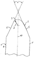
- An embodiment of the invention is based on the attached Figure showing the cross section of the cutting area shows a punch knife, explained in more detail.
- the punch knife 1 shown in the figure essentially corresponds a punch knife such as that in DE 39 28 916 C1 is shown.
- a number of such punch knives are used in usually together with crease lines at the bottom of one Carrier plate of a punching tool attached to a punching machine.
- the punching knives are used for punching out, for example of folding boxes from one lying on a counter punching plate Carton.
- the carrier plate pressurized and towards the counter-punching plate moves until the punching knife touches the counter punching plate and the box is cut. Then the carrier plate moved away from the counter punch plate.
- the punch knife 1 is elongated and has on its the counter-punching plate (not shown) facing end a symmetrical, in its longitudinal direction running cutting edge 2.
- the cutting edge 2 has two symmetrical to the longitudinal center plane 10 of the punching knife 1 extending oblique flanks 5, 6 on that at an angle of preferably 30 to 60 ° to each other run and into the side flanks 7, 8 of the punch knife 1 pass over.
- At the outer end of the punch knife 1 go Sloping flanks 5, 6 into a rounding 9 connecting them, which is also symmetrical to the longitudinal center plane 10 of the punch knife 1 is.
- the fillet 9 has a radius of 0.005 to 0.020 mm.
- the rounded cutting edge 2 can additionally be hardened or be surface finished.
- the rounded die cutters with the increased surface area reduce the fact that the cutting edge when punching does not dig the impression so deeply into the stamping plate, so that the print on the impression is not so big. This is more sensitive The surface to be cut is gentle.
- the reduced footprint due to the increased contact area between the cutting edge and stamping plate reduces the notch stresses in the area of Burial and thus the premature occurrence of fatigue fractures in the punching plate.
- the punch knives lose in connection with wear Height. There can therefore be a compromise between increased resilience the cutting edge and wear.
- a cutting radius of 0.020 mm is considered special viewed favorably.
- the rounding of the cutting edge can be created mechanically, by remelting e.g. using a laser with the appropriate Heat conduction on normal and cutting-hardened punch knives, the as strip steel lines or from the full machined punching lines as flat flat tools or as curved ones for rotary tools attack.
Landscapes
- Life Sciences & Earth Sciences (AREA)
- Forests & Forestry (AREA)
- Engineering & Computer Science (AREA)
- Mechanical Engineering (AREA)
- Perforating, Stamping-Out Or Severing By Means Other Than Cutting (AREA)
- Nonmetal Cutting Devices (AREA)
- Polishing Bodies And Polishing Tools (AREA)
- Heat Treatment Of Articles (AREA)
- Making Paper Articles (AREA)
Description
Claims (3)
- Stanzmesser zum Ausstanzen von Teilen beliebiger Form aus Papier, Karton, Pappe, Kunststoffolien, Leder, Gummi und dgl., wobei die Schneidenkannte eine Verrundung mit einem Radius aufweist gekennzeichnet durch eine Schneidenkante (2), die eine Verrundung (9) mit einem Radius (3) von 0,005 bis 0,020 mm aufweist, wobei der Schneidenwinkel (4) der Schneidenkante (2) 30 bis 60° beträgt.
- Stanzmesser nach Anspruch 1, dadurch gekennzeichnet, daß die verrundete Schneidenkante (2) zusätzlich gehärtet ist.
- Stanzmesser nach Anspruch 1, dadurch gekennzeichnet, daß die verrundete Schneidenkante (2) oberflächenveredelt ist.
Applications Claiming Priority (2)
| Application Number | Priority Date | Filing Date | Title |
|---|---|---|---|
| DE4443613 | 1994-12-07 | ||
| DE4443613A DE4443613C1 (de) | 1994-12-07 | 1994-12-07 | Stanzmesser mit verrundeter Schneide |
Publications (2)
| Publication Number | Publication Date |
|---|---|
| EP0715933A1 EP0715933A1 (de) | 1996-06-12 |
| EP0715933B1 true EP0715933B1 (de) | 1999-06-16 |
Family
ID=6535200
Family Applications (1)
| Application Number | Title | Priority Date | Filing Date |
|---|---|---|---|
| EP95117933A Expired - Lifetime EP0715933B1 (de) | 1994-12-07 | 1995-11-14 | Stanzmesser |
Country Status (7)
| Country | Link |
|---|---|
| US (1) | US5967015A (de) |
| EP (1) | EP0715933B1 (de) |
| JP (1) | JPH08216098A (de) |
| CN (1) | CN1129631A (de) |
| AT (1) | ATE181274T1 (de) |
| CZ (1) | CZ322095A3 (de) |
| DE (2) | DE4443613C1 (de) |
Cited By (2)
| Publication number | Priority date | Publication date | Assignee | Title |
|---|---|---|---|---|
| DE102011014858A1 (de) | 2010-04-20 | 2011-10-20 | Heidelberger Druckmaschinen Ag | Stanzstation mit Zurichtvorrichtung |
| DE102010061991B4 (de) * | 2010-11-25 | 2016-06-09 | Bayerische Motoren Werke Aktiengesellschaft | Verfahren zum Stanzen einer aus Fasermaterial bestehenden Fasermatte |
Families Citing this family (21)
| Publication number | Priority date | Publication date | Assignee | Title |
|---|---|---|---|---|
| DE29809958U1 (de) | 1998-06-04 | 1998-08-27 | Essmann + Schaefer GmbH + Co. KG, 42369 Wuppertal | Schneid- und Ritzwerkzeug |
| DE29922281U1 (de) * | 1999-12-20 | 2001-04-26 | Essmann + Schaefer GmbH + Co. KG, 42369 Wuppertal | Schneid- und Ritzwerkzeug |
| JP2007075938A (ja) * | 2005-09-13 | 2007-03-29 | Carl Manufacturing Co Ltd | パンチ刃 |
| JP4826227B2 (ja) * | 2005-11-21 | 2011-11-30 | 三菱マテリアル株式会社 | ロータリーダイ |
| JP4831318B2 (ja) * | 2006-02-27 | 2011-12-07 | 大日本印刷株式会社 | シート打抜型設計方法 |
| SE530194C2 (sv) * | 2006-07-10 | 2008-03-25 | Sandvik Intellectual Property | En egg hos ett knivorgan för en knivvals |
| US7909902B2 (en) | 2008-06-12 | 2011-03-22 | International Business Machines Corporation | Modified hexagonal perforated pattern |
| AT508551B1 (de) * | 2010-01-26 | 2011-02-15 | Boehler Uddeholm Prec Strip Gmbh | Stanzwerkzeug |
| SE534677C2 (sv) * | 2010-03-23 | 2011-11-15 | Sandvik Intellectual Property | Stålstanskniv |
| US9102818B2 (en) | 2010-05-17 | 2015-08-11 | Highcon Systems Ltd. | Method and system for surface adhesive rule technology |
| US8777828B2 (en) | 2010-05-17 | 2014-07-15 | Highcon Systems Ltd. | Method and system for creating co-layer surface adhesive rule |
| JP5146591B1 (ja) * | 2011-12-22 | 2013-02-20 | 横浜ゴム株式会社 | 空気入りタイヤの製造方法 |
| JP5766886B2 (ja) * | 2012-09-28 | 2015-08-19 | 株式会社アライドマテリアル | 平刃状切断刃およびグリーンシート切断刃 |
| CN107249836B (zh) * | 2015-01-26 | 2020-06-16 | 理研科技株式会社 | 树脂制面板的生产方法 |
| JP6495959B2 (ja) * | 2017-02-14 | 2019-04-03 | 株式会社東北田村工機 | 打抜き刃 |
| CN109702781A (zh) * | 2018-08-29 | 2019-05-03 | 深圳市宝明科技股份有限公司 | 一种导光板冲切刀具及冲切方法 |
| KR102030057B1 (ko) * | 2019-08-13 | 2019-10-08 | 이준범 | 칼날을 오래 사용하고 음식물이 달라붙지 않는 칼 |
| FR3100475B1 (fr) * | 2019-09-06 | 2021-08-06 | Safran Nacelles | Procédé et machine de découpe d’éléments de drapage |
| EP3835018A1 (de) * | 2019-12-12 | 2021-06-16 | Ceratizit Luxembourg Sàrl | Schneidelement und verwendung davon |
| DE102020120576A1 (de) * | 2020-08-04 | 2022-02-10 | Hauni Maschinenbau Gmbh | Hartmetallmesser für Strangschnitt und Messerhalter |
| JP2024112328A (ja) * | 2021-06-17 | 2024-08-21 | 株式会社ファインテック | 刃物および刃物の製造方法 |
Family Cites Families (8)
| Publication number | Priority date | Publication date | Assignee | Title |
|---|---|---|---|---|
| US2349336A (en) * | 1940-04-23 | 1944-05-23 | Fred Goat Co Inc | Cutting blade and method of cutting therewith |
| US2361288A (en) * | 1944-04-17 | 1944-10-24 | Simonds Saw & Steel Co | Cutting rule |
| BE790308A (fr) * | 1971-10-22 | 1973-02-15 | Boehler & Co Ag Geb | Lampe d'etampe a tranchant dentele |
| DE3135980C1 (de) * | 1981-09-11 | 1983-06-01 | Karl Marbach Gmbh & Co, 7100 Heilbronn | Bandstahlstanzwerkzeug mit mindestens einem eine Schneide aufweisenden bandförmigen Stanzmesser |
| DE3317777C1 (de) * | 1983-05-16 | 1984-09-13 | R + S Stanzformen GmbH, 6000 Frankfurt | Bandstahlstanzwerkzeug fuer Zuschnitte aus Karton od.dgl. |
| US4526077A (en) * | 1983-07-21 | 1985-07-02 | Detroit Punch & Retainer Corporation | Heavy duty punch |
| AT394680B (de) * | 1988-02-03 | 1992-05-25 | Boehler Gmbh | Linien- schneidmesser fuer die bearbeitung von flaechigem material |
| DE3928916C1 (de) * | 1989-08-31 | 1991-01-24 | Karl Marbach Gmbh & Co, 7100 Heilbronn, De |
-
1994
- 1994-12-07 DE DE4443613A patent/DE4443613C1/de not_active Expired - Lifetime
-
1995
- 1995-11-14 AT AT95117933T patent/ATE181274T1/de active
- 1995-11-14 EP EP95117933A patent/EP0715933B1/de not_active Expired - Lifetime
- 1995-11-14 DE DE59506228T patent/DE59506228D1/de not_active Expired - Fee Related
- 1995-12-05 CZ CZ953220A patent/CZ322095A3/cs unknown
- 1995-12-07 JP JP7319407A patent/JPH08216098A/ja active Pending
- 1995-12-07 CN CN95117597A patent/CN1129631A/zh active Pending
-
1997
- 1997-08-29 US US08/921,403 patent/US5967015A/en not_active Expired - Lifetime
Cited By (2)
| Publication number | Priority date | Publication date | Assignee | Title |
|---|---|---|---|---|
| DE102011014858A1 (de) | 2010-04-20 | 2011-10-20 | Heidelberger Druckmaschinen Ag | Stanzstation mit Zurichtvorrichtung |
| DE102010061991B4 (de) * | 2010-11-25 | 2016-06-09 | Bayerische Motoren Werke Aktiengesellschaft | Verfahren zum Stanzen einer aus Fasermaterial bestehenden Fasermatte |
Also Published As
| Publication number | Publication date |
|---|---|
| CZ322095A3 (en) | 1996-06-12 |
| JPH08216098A (ja) | 1996-08-27 |
| DE4443613C1 (de) | 1996-04-25 |
| EP0715933A1 (de) | 1996-06-12 |
| DE59506228D1 (de) | 1999-07-22 |
| CN1129631A (zh) | 1996-08-28 |
| US5967015A (en) | 1999-10-19 |
| ATE181274T1 (de) | 1999-07-15 |
Similar Documents
| Publication | Publication Date | Title |
|---|---|---|
| DE4443613C1 (de) | Stanzmesser mit verrundeter Schneide | |
| EP0321590B1 (de) | Verfahren und Vorrichtung zum Herstellen eines eine scharfe Schneidkante aufweisenden Stanzwerkzeugs | |
| DE3928916C1 (de) | ||
| DE69819476T2 (de) | Rotationsstanzwerkzeug | |
| DE102013223854A1 (de) | Vorrichtung und Verfahren zum Rillen von Wellpappe und Vollpappe | |
| EP0418768B1 (de) | Stanzblech und Verfahren zu seiner Herstellung | |
| DE3108691A1 (de) | Schneide- und/oder rillmaschine fuer papier-, pappen- oder schichtpressstoffrollen | |
| DE202013100883U1 (de) | Zurichtebogen für ein Bandstahl-Stanzwerkzeug | |
| EP3756842B1 (de) | Kiss-cut-ziehmesser | |
| DE60300938T2 (de) | Maschine zum ausstanzen von zuschnitten aus einer wellpappenbahn und ausbilden von falzlinien in den zuschnitten | |
| EP3168016B1 (de) | Schneidwerkzeug zum trennen von flachmaterialien | |
| DE2520346A1 (de) | Rotationsstanzwerkzeug und verfahren zu seiner herstellung | |
| DE1452590C3 (de) | Verfahren zum Herstellen von Trockenrasietapparat-Scherfolien | |
| DE2953739T1 (de) | ||
| EP1990152B1 (de) | Kantenanleimaggregat und Verfahren zum Anleimen von Kantenmaterial | |
| DE2708739C3 (de) | Bandstahlmesser für Holzzerspanungsmaschinen | |
| DE1291188B (de) | Schneidmesser fuer eine Perforationsmaschine | |
| DE102016123374A1 (de) | Vorrichtung und Verfahren zum Rillen von Wellpappe und Vollpappe | |
| DE29922281U1 (de) | Schneid- und Ritzwerkzeug | |
| DE3206681A1 (de) | Hydraulisch angetriebene schneidemaschine fuer papierbogen od. dgl. | |
| AT390753B (de) | Fuehrung von flaechenmaterial in anlagen mit rundmessern | |
| EP0044550A1 (de) | Verfahren und Vorrichtung zum Aufteilen einer Platte aus Spanplattenmaterial | |
| DE102014102552B4 (de) | Stanzvorrichtung und Verfahren zum Stanzen von Wellpappe | |
| CH662089A5 (en) | Device for bevelling edges of a mount of a punching backing plate | |
| DE3301199A1 (de) | Schneidwerkzeuge mit zementiertem carbid und verfahren zur herstellung und verwendung |
Legal Events
| Date | Code | Title | Description |
|---|---|---|---|
| PUAI | Public reference made under article 153(3) epc to a published international application that has entered the european phase |
Free format text: ORIGINAL CODE: 0009012 |
|
| AK | Designated contracting states |
Kind code of ref document: A1 Designated state(s): AT DE FR GB IT SE |
|
| 17P | Request for examination filed |
Effective date: 19960802 |
|
| 17Q | First examination report despatched |
Effective date: 19980401 |
|
| GRAG | Despatch of communication of intention to grant |
Free format text: ORIGINAL CODE: EPIDOS AGRA |
|
| GRAG | Despatch of communication of intention to grant |
Free format text: ORIGINAL CODE: EPIDOS AGRA |
|
| GRAH | Despatch of communication of intention to grant a patent |
Free format text: ORIGINAL CODE: EPIDOS IGRA |
|
| GRAH | Despatch of communication of intention to grant a patent |
Free format text: ORIGINAL CODE: EPIDOS IGRA |
|
| GRAA | (expected) grant |
Free format text: ORIGINAL CODE: 0009210 |
|
| AK | Designated contracting states |
Kind code of ref document: B1 Designated state(s): AT DE FR GB IT SE |
|
| PG25 | Lapsed in a contracting state [announced via postgrant information from national office to epo] |
Ref country code: FR Free format text: LAPSE BECAUSE OF FAILURE TO SUBMIT A TRANSLATION OF THE DESCRIPTION OR TO PAY THE FEE WITHIN THE PRESCRIBED TIME-LIMIT Effective date: 19990616 |
|
| REF | Corresponds to: |
Ref document number: 181274 Country of ref document: AT Date of ref document: 19990715 Kind code of ref document: T |
|
| REF | Corresponds to: |
Ref document number: 59506228 Country of ref document: DE Date of ref document: 19990722 |
|
| ITF | It: translation for a ep patent filed | ||
| GBT | Gb: translation of ep patent filed (gb section 77(6)(a)/1977) |
Effective date: 19990917 |
|
| EN | Fr: translation not filed | ||
| PLBQ | Unpublished change to opponent data |
Free format text: ORIGINAL CODE: EPIDOS OPPO |
|
| PLBI | Opposition filed |
Free format text: ORIGINAL CODE: 0009260 |
|
| PLBF | Reply of patent proprietor to notice(s) of opposition |
Free format text: ORIGINAL CODE: EPIDOS OBSO |
|
| 26 | Opposition filed |
Opponent name: BOEHLER-YBBSTAL BAND GMBH & CO KG Effective date: 20000315 |
|
| PG25 | Lapsed in a contracting state [announced via postgrant information from national office to epo] |
Ref country code: DE Free format text: LAPSE BECAUSE OF NON-PAYMENT OF DUE FEES Effective date: 20000901 |
|
| PLBF | Reply of patent proprietor to notice(s) of opposition |
Free format text: ORIGINAL CODE: EPIDOS OBSO |
|
| PLBL | Opposition procedure terminated |
Free format text: ORIGINAL CODE: EPIDOS OPPC |
|
| PLBM | Termination of opposition procedure: date of legal effect published |
Free format text: ORIGINAL CODE: 0009276 |
|
| STAA | Information on the status of an ep patent application or granted ep patent |
Free format text: STATUS: OPPOSITION PROCEDURE CLOSED |
|
| 27C | Opposition proceedings terminated |
Effective date: 20000923 |
|
| REG | Reference to a national code |
Ref country code: GB Ref legal event code: IF02 |
|
| PLAB | Opposition data, opponent's data or that of the opponent's representative modified |
Free format text: ORIGINAL CODE: 0009299OPPO |
|
| PGFP | Annual fee paid to national office [announced via postgrant information from national office to epo] |
Ref country code: GB Payment date: 20141121 Year of fee payment: 20 Ref country code: SE Payment date: 20141120 Year of fee payment: 20 |
|
| PGFP | Annual fee paid to national office [announced via postgrant information from national office to epo] |
Ref country code: AT Payment date: 20141126 Year of fee payment: 20 |
|
| PGFP | Annual fee paid to national office [announced via postgrant information from national office to epo] |
Ref country code: IT Payment date: 20141122 Year of fee payment: 20 |
|
| REG | Reference to a national code |
Ref country code: GB Ref legal event code: PE20 Expiry date: 20151113 |
|
| REG | Reference to a national code |
Ref country code: AT Ref legal event code: MK07 Ref document number: 181274 Country of ref document: AT Kind code of ref document: T Effective date: 20151114 |
|
| PG25 | Lapsed in a contracting state [announced via postgrant information from national office to epo] |
Ref country code: GB Free format text: LAPSE BECAUSE OF EXPIRATION OF PROTECTION Effective date: 20151113 |