EP0715947A2 - Noyau pour la confection de pneumatiques - Google Patents
Noyau pour la confection de pneumatiques Download PDFInfo
- Publication number
- EP0715947A2 EP0715947A2 EP95118997A EP95118997A EP0715947A2 EP 0715947 A2 EP0715947 A2 EP 0715947A2 EP 95118997 A EP95118997 A EP 95118997A EP 95118997 A EP95118997 A EP 95118997A EP 0715947 A2 EP0715947 A2 EP 0715947A2
- Authority
- EP
- European Patent Office
- Prior art keywords
- core
- tire
- features
- core according
- shell
- Prior art date
- Legal status (The legal status is an assumption and is not a legal conclusion. Google has not performed a legal analysis and makes no representation as to the accuracy of the status listed.)
- Granted
Links
- 238000004073 vulcanization Methods 0.000 claims abstract description 32
- 238000010438 heat treatment Methods 0.000 claims abstract description 13
- 238000010276 construction Methods 0.000 claims abstract description 8
- 229920001169 thermoplastic Polymers 0.000 claims abstract description 8
- 239000004416 thermosoftening plastic Substances 0.000 claims abstract description 8
- 238000012856 packing Methods 0.000 claims description 9
- 239000000463 material Substances 0.000 claims description 5
- 230000009477 glass transition Effects 0.000 claims description 3
- 238000007493 shaping process Methods 0.000 claims description 3
- 238000007664 blowing Methods 0.000 claims 2
- 238000004804 winding Methods 0.000 abstract description 20
- 238000000034 method Methods 0.000 abstract description 8
- 230000002093 peripheral effect Effects 0.000 description 7
- 238000004519 manufacturing process Methods 0.000 description 6
- 238000007789 sealing Methods 0.000 description 6
- 239000011324 bead Substances 0.000 description 4
- 238000001746 injection moulding Methods 0.000 description 4
- 239000007787 solid Substances 0.000 description 4
- 238000013459 approach Methods 0.000 description 3
- 230000015572 biosynthetic process Effects 0.000 description 3
- 238000000748 compression moulding Methods 0.000 description 3
- 239000000945 filler Substances 0.000 description 3
- 238000003780 insertion Methods 0.000 description 3
- 230000037431 insertion Effects 0.000 description 3
- 238000012432 intermediate storage Methods 0.000 description 3
- 239000004033 plastic Substances 0.000 description 3
- 238000003860 storage Methods 0.000 description 3
- 208000002197 Ehlers-Danlos syndrome Diseases 0.000 description 2
- QXJJQWWVWRCVQT-UHFFFAOYSA-K calcium;sodium;phosphate Chemical compound [Na+].[Ca+2].[O-]P([O-])([O-])=O QXJJQWWVWRCVQT-UHFFFAOYSA-K 0.000 description 2
- 238000005520 cutting process Methods 0.000 description 2
- 238000013461 design Methods 0.000 description 2
- 238000005516 engineering process Methods 0.000 description 2
- 239000011521 glass Substances 0.000 description 2
- 229920001643 poly(ether ketone) Polymers 0.000 description 2
- 239000004417 polycarbonate Substances 0.000 description 2
- 229920000515 polycarbonate Polymers 0.000 description 2
- 239000007795 chemical reaction product Substances 0.000 description 1
- 239000011258 core-shell material Substances 0.000 description 1
- 230000000694 effects Effects 0.000 description 1
- 230000008020 evaporation Effects 0.000 description 1
- 238000001704 evaporation Methods 0.000 description 1
- 230000008018 melting Effects 0.000 description 1
- 238000002844 melting Methods 0.000 description 1
- 239000002184 metal Substances 0.000 description 1
- 238000000465 moulding Methods 0.000 description 1
- 238000000926 separation method Methods 0.000 description 1
- 239000012815 thermoplastic material Substances 0.000 description 1
- 230000007704 transition Effects 0.000 description 1
Images



Classifications
-
- B—PERFORMING OPERATIONS; TRANSPORTING
- B29—WORKING OF PLASTICS; WORKING OF SUBSTANCES IN A PLASTIC STATE IN GENERAL
- B29C—SHAPING OR JOINING OF PLASTICS; SHAPING OF MATERIAL IN A PLASTIC STATE, NOT OTHERWISE PROVIDED FOR; AFTER-TREATMENT OF THE SHAPED PRODUCTS, e.g. REPAIRING
- B29C66/00—General aspects of processes or apparatus for joining preformed parts
- B29C66/50—General aspects of joining tubular articles; General aspects of joining long products, i.e. bars or profiled elements; General aspects of joining single elements to tubular articles, hollow articles or bars; General aspects of joining several hollow-preforms to form hollow or tubular articles
- B29C66/51—Joining tubular articles, profiled elements or bars; Joining single elements to tubular articles, hollow articles or bars; Joining several hollow-preforms to form hollow or tubular articles
- B29C66/54—Joining several hollow-preforms, e.g. half-shells, to form hollow articles, e.g. for making balls, containers; Joining several hollow-preforms, e.g. half-cylinders, to form tubular articles
-
- B—PERFORMING OPERATIONS; TRANSPORTING
- B29—WORKING OF PLASTICS; WORKING OF SUBSTANCES IN A PLASTIC STATE IN GENERAL
- B29C—SHAPING OR JOINING OF PLASTICS; SHAPING OF MATERIAL IN A PLASTIC STATE, NOT OTHERWISE PROVIDED FOR; AFTER-TREATMENT OF THE SHAPED PRODUCTS, e.g. REPAIRING
- B29C33/00—Moulds or cores; Details thereof or accessories therefor
- B29C33/44—Moulds or cores; Details thereof or accessories therefor with means for, or specially constructed to facilitate, the removal of articles, e.g. of undercut articles
- B29C33/48—Moulds or cores; Details thereof or accessories therefor with means for, or specially constructed to facilitate, the removal of articles, e.g. of undercut articles with means for collapsing or disassembling
- B29C33/50—Moulds or cores; Details thereof or accessories therefor with means for, or specially constructed to facilitate, the removal of articles, e.g. of undercut articles with means for collapsing or disassembling elastic or flexible
- B29C33/505—Moulds or cores; Details thereof or accessories therefor with means for, or specially constructed to facilitate, the removal of articles, e.g. of undercut articles with means for collapsing or disassembling elastic or flexible cores or mandrels, e.g. inflatable
-
- B—PERFORMING OPERATIONS; TRANSPORTING
- B29—WORKING OF PLASTICS; WORKING OF SUBSTANCES IN A PLASTIC STATE IN GENERAL
- B29C—SHAPING OR JOINING OF PLASTICS; SHAPING OF MATERIAL IN A PLASTIC STATE, NOT OTHERWISE PROVIDED FOR; AFTER-TREATMENT OF THE SHAPED PRODUCTS, e.g. REPAIRING
- B29C43/00—Compression moulding, i.e. applying external pressure to flow the moulding material; Apparatus therefor
- B29C43/02—Compression moulding, i.e. applying external pressure to flow the moulding material; Apparatus therefor of articles of definite length, i.e. discrete articles
- B29C43/10—Isostatic pressing, i.e. using non-rigid pressure-exerting members against rigid parts or dies
- B29C43/102—Isostatic pressing, i.e. using non-rigid pressure-exerting members against rigid parts or dies using rigid mould parts specially adapted for moulding articles having an axis of symmetry
- B29C43/104—Isostatic pressing, i.e. using non-rigid pressure-exerting members against rigid parts or dies using rigid mould parts specially adapted for moulding articles having an axis of symmetry the mould cavity lying totally outside the axis of symmetry, e.g. toroidal moulds
-
- B—PERFORMING OPERATIONS; TRANSPORTING
- B29—WORKING OF PLASTICS; WORKING OF SUBSTANCES IN A PLASTIC STATE IN GENERAL
- B29C—SHAPING OR JOINING OF PLASTICS; SHAPING OF MATERIAL IN A PLASTIC STATE, NOT OTHERWISE PROVIDED FOR; AFTER-TREATMENT OF THE SHAPED PRODUCTS, e.g. REPAIRING
- B29C43/00—Compression moulding, i.e. applying external pressure to flow the moulding material; Apparatus therefor
- B29C43/32—Component parts, details or accessories; Auxiliary operations
- B29C43/36—Moulds for making articles of definite length, i.e. discrete articles
- B29C43/3642—Bags, bleeder sheets or cauls for isostatic pressing
-
- B—PERFORMING OPERATIONS; TRANSPORTING
- B29—WORKING OF PLASTICS; WORKING OF SUBSTANCES IN A PLASTIC STATE IN GENERAL
- B29C—SHAPING OR JOINING OF PLASTICS; SHAPING OF MATERIAL IN A PLASTIC STATE, NOT OTHERWISE PROVIDED FOR; AFTER-TREATMENT OF THE SHAPED PRODUCTS, e.g. REPAIRING
- B29C53/00—Shaping by bending, folding, twisting, straightening or flattening; Apparatus therefor
- B29C53/56—Winding and joining, e.g. winding spirally
- B29C53/58—Winding and joining, e.g. winding spirally helically
- B29C53/583—Winding and joining, e.g. winding spirally helically for making tubular articles with particular features
- B29C53/588—Winding and joining, e.g. winding spirally helically for making tubular articles with particular features having a non-linear axis, e.g. elbows, toroids
-
- B—PERFORMING OPERATIONS; TRANSPORTING
- B29—WORKING OF PLASTICS; WORKING OF SUBSTANCES IN A PLASTIC STATE IN GENERAL
- B29C—SHAPING OR JOINING OF PLASTICS; SHAPING OF MATERIAL IN A PLASTIC STATE, NOT OTHERWISE PROVIDED FOR; AFTER-TREATMENT OF THE SHAPED PRODUCTS, e.g. REPAIRING
- B29C65/00—Joining or sealing of preformed parts, e.g. welding of plastics materials; Apparatus therefor
- B29C65/02—Joining or sealing of preformed parts, e.g. welding of plastics materials; Apparatus therefor by heating, with or without pressure
-
- B—PERFORMING OPERATIONS; TRANSPORTING
- B29—WORKING OF PLASTICS; WORKING OF SUBSTANCES IN A PLASTIC STATE IN GENERAL
- B29C—SHAPING OR JOINING OF PLASTICS; SHAPING OF MATERIAL IN A PLASTIC STATE, NOT OTHERWISE PROVIDED FOR; AFTER-TREATMENT OF THE SHAPED PRODUCTS, e.g. REPAIRING
- B29C66/00—General aspects of processes or apparatus for joining preformed parts
- B29C66/50—General aspects of joining tubular articles; General aspects of joining long products, i.e. bars or profiled elements; General aspects of joining single elements to tubular articles, hollow articles or bars; General aspects of joining several hollow-preforms to form hollow or tubular articles
- B29C66/63—Internally supporting the article during joining
-
- B—PERFORMING OPERATIONS; TRANSPORTING
- B29—WORKING OF PLASTICS; WORKING OF SUBSTANCES IN A PLASTIC STATE IN GENERAL
- B29D—PRODUCING PARTICULAR ARTICLES FROM PLASTICS OR FROM SUBSTANCES IN A PLASTIC STATE
- B29D30/00—Producing pneumatic or solid tyres or parts thereof
- B29D30/06—Pneumatic tyres or parts thereof (e.g. produced by casting, moulding, compression moulding, injection moulding, centrifugal casting)
- B29D30/0601—Vulcanising tyres; Vulcanising presses for tyres
- B29D30/0661—Rigid cores therefor, e.g. annular or substantially toroidal cores
-
- B—PERFORMING OPERATIONS; TRANSPORTING
- B29—WORKING OF PLASTICS; WORKING OF SUBSTANCES IN A PLASTIC STATE IN GENERAL
- B29D—PRODUCING PARTICULAR ARTICLES FROM PLASTICS OR FROM SUBSTANCES IN A PLASTIC STATE
- B29D30/00—Producing pneumatic or solid tyres or parts thereof
- B29D30/06—Pneumatic tyres or parts thereof (e.g. produced by casting, moulding, compression moulding, injection moulding, centrifugal casting)
- B29D30/08—Building tyres
- B29D30/10—Building tyres on round cores, i.e. the shape of the core is approximately identical with the shape of the completed tyre
- B29D30/12—Cores
-
- B—PERFORMING OPERATIONS; TRANSPORTING
- B29—WORKING OF PLASTICS; WORKING OF SUBSTANCES IN A PLASTIC STATE IN GENERAL
- B29C—SHAPING OR JOINING OF PLASTICS; SHAPING OF MATERIAL IN A PLASTIC STATE, NOT OTHERWISE PROVIDED FOR; AFTER-TREATMENT OF THE SHAPED PRODUCTS, e.g. REPAIRING
- B29C33/00—Moulds or cores; Details thereof or accessories therefor
- B29C33/02—Moulds or cores; Details thereof or accessories therefor with incorporated heating or cooling means
-
- B—PERFORMING OPERATIONS; TRANSPORTING
- B29—WORKING OF PLASTICS; WORKING OF SUBSTANCES IN A PLASTIC STATE IN GENERAL
- B29C—SHAPING OR JOINING OF PLASTICS; SHAPING OF MATERIAL IN A PLASTIC STATE, NOT OTHERWISE PROVIDED FOR; AFTER-TREATMENT OF THE SHAPED PRODUCTS, e.g. REPAIRING
- B29C33/00—Moulds or cores; Details thereof or accessories therefor
- B29C33/44—Moulds or cores; Details thereof or accessories therefor with means for, or specially constructed to facilitate, the removal of articles, e.g. of undercut articles
- B29C33/48—Moulds or cores; Details thereof or accessories therefor with means for, or specially constructed to facilitate, the removal of articles, e.g. of undercut articles with means for collapsing or disassembling
- B29C33/50—Moulds or cores; Details thereof or accessories therefor with means for, or specially constructed to facilitate, the removal of articles, e.g. of undercut articles with means for collapsing or disassembling elastic or flexible
-
- B—PERFORMING OPERATIONS; TRANSPORTING
- B29—WORKING OF PLASTICS; WORKING OF SUBSTANCES IN A PLASTIC STATE IN GENERAL
- B29C—SHAPING OR JOINING OF PLASTICS; SHAPING OF MATERIAL IN A PLASTIC STATE, NOT OTHERWISE PROVIDED FOR; AFTER-TREATMENT OF THE SHAPED PRODUCTS, e.g. REPAIRING
- B29C66/00—General aspects of processes or apparatus for joining preformed parts
- B29C66/70—General aspects of processes or apparatus for joining preformed parts characterised by the composition, physical properties or the structure of the material of the parts to be joined; Joining with non-plastics material
- B29C66/73—General aspects of processes or apparatus for joining preformed parts characterised by the composition, physical properties or the structure of the material of the parts to be joined; Joining with non-plastics material characterised by the intensive physical properties of the material of the parts to be joined, by the optical properties of the material of the parts to be joined, by the extensive physical properties of the parts to be joined, by the state of the material of the parts to be joined or by the material of the parts to be joined being a thermoplastic or a thermoset
- B29C66/731—General aspects of processes or apparatus for joining preformed parts characterised by the composition, physical properties or the structure of the material of the parts to be joined; Joining with non-plastics material characterised by the intensive physical properties of the material of the parts to be joined, by the optical properties of the material of the parts to be joined, by the extensive physical properties of the parts to be joined, by the state of the material of the parts to be joined or by the material of the parts to be joined being a thermoplastic or a thermoset characterised by the intensive physical properties of the material of the parts to be joined
- B29C66/7311—Thermal properties
- B29C66/73117—Tg, i.e. glass transition temperature
Definitions
- the invention relates to a core for building a pneumatic vehicle tire with side walls and tread. It is known to produce the carcass of a pneumatic vehicle tire by wrapping an annular core around it and then separating the carcass layer formed radially below the core by cutting in the circumferential direction over the entire circumference and then folding over the edges created by the separation in order to produce a tire bead around the tire cores .
- Such tires are known for example from DE-OS 1934018.
- Such cores are usually removed from the tire in succession after the tire has been built up, for example by folding in (DE-OS 1934018) or by removing the individual segments of an annular core EP 0481805 A2 which is divided into peripheral segments.
- the tires are temporarily stored and, after a predetermined storage time, inserted into the vulcanization press without being centered.
- the bellows of the vulcanization press are filled with superheated steam from the inside, causing the desired elevation to securely press the outer contour of the tire into the profiled inner contour of the recess.
- This conventional production requires a series of individual steps by completely removing the tire from the mold, then intermediate storage without a mold, a core and an additional bladder in the vulcanization press, on which the tire is placed more or less precisely without being centered.
- the insertion accuracy left to chance in the heating press poses problems with regard to the concentricity (uniformity) of the tire produced.
- the associated dangers can only be at least partially reduced with additional effort and corresponding experience of the operating personnel.
- EP 0481805 indicates the possibility of removing the tire from the rigid, segmented core only after vulcanization has taken place.
- a rigid core With such a rigid core, however, the elevation generated in conventional vulcanization presses by the bladder from the radial inside, which reliably presses the green tire into the inner contour of the shape surrounding the tire, is not readily possible. Reliable shaping of the profile, especially in the tread pattern, does not seem to be guaranteed without additional measures with such a stiff core.
- the reliable heating that is generated in conventional vulcanization presses via the bladder from the radial inside by the superheated steam is also not guaranteed.
- the many circumferential segments result in a series of gaps between the individual segments, which favors the formation of circumferentially distributed burrs of rubber material which pushes into the gaps. Since such occurrences are distributed at certain points in the circumferential direction and these burrs are not necessarily formed uniformly, this can also result in additional uniformity problems.
- the invention is therefore based on the object of providing a core for the construction of a pneumatic vehicle tire for use on conventional rims by winding technology, by means of which the structure and vulcanization of the tire is improved by simple means.
- the object is achieved according to the invention by a core according to the features of claim 1.
- the manufacturing simplifications and cost advantages of the winding technology for producing a conventional tubeless tire that is open radially towards the rim and can be mounted with its bead cores on conventional rims is considerably simplified by the design of the core as a bellows for vulcanization.
- a tire of this type in the state built up on the core, can be inserted together with the core into the vulcanization press.
- the bladder in the Vulcanization press filled with heating steam in accordance with the controlled processes already known from conventional vulcanization systems.
- the core expands due to the superheated steam and provides for the necessary elevation of the tire, so that the blank is reliably pressed into the inner profile of the outer shape surrounding the tire.
- the desired profile of the tire is formed safely and without loss of quality compared to conventional vulcanizing devices.
- the temperature profile inside the tire can also be guaranteed on the basis of the known control processes. Additional canting, deformation, the uniformity problems, which can lead to uniformity problems due to canting, deformation or damage during the dismantling of the blank from the core or when inserting the blank, which is not supported from the inside, into a vulcanization press in conventional tire production, are largely eliminated.
- thermoplastic shell enables a rigid, solid core which favors a very precise construction of the carcass.
- the tire can be built exactly on the outer contour of the shell, which corresponds to the desired inner contour of the tire. Uniformity problems due to possible deformations of the winding core during assembly are thus minimized.
- the shell is plasticized in the vulcanization press due to the increasing temperature, so that it is still before the vulcanization temperature is reached due to the Heat from inside with internal pressure expands and the desired elevation of the tire for optimal treading takes place.
- the core is preferably designed to be fastened on a centering element.
- a centering element With the aid of the centering element, a centered core structure is ensured and the centering element can be fastened in the vulcanizing device without great effort, which also ensures centering of the core and thus of the tire in the vulcanizing device. Without the additional effort of more or less inaccurate adjustment, as is usual with conventional insertion, the tire can be vulcanized precisely in the centered position built up. This further reduces the uniformity problems.
- thermoplastic shell is preferably constructed from two concentric half shells that extend over the circumference. These are simple to produce, for example by compression molding or injection molding, and produce a maximum of one circumferential gap in the assembled state. This reduces the problems of uniformity due to the formation of burrs.
- the winding core is preferably constructed from thermoplastic, polymeric material, the glass transition temperature of which is above RT (room temperature) and which is thermally stable up to 200 ° C.
- This material gives the shell the necessary hardness and changes to a thermoplastic state at temperatures above room temperature. These temperatures are below the usual vulcanization temperatures up to 200 °.
- Polycarbonate or polyether ketone is particularly easy to process further using suitable standard processes, for example compression molding or injection molding.
- the core according to the features of claim 6 represents a further preferred embodiment.
- a firm core is produced.
- the tightly packed fillers give the surrounding elastic shell sufficient strength to build up the tire.
- the internal pressure is increased in the vulcanizing device, so that the elastic shell expands and thus ensures the necessary elevation of the tire for reliable tread generation.
- the core is solidified in a particularly dimensionally stable manner.
- the packing elements can be reliably fed in before the tire structure to produce the desired contour and removed again after the vulcanization process or after insertion into the vulcanization trough before the vulcanization process become.
- the elastic shell can be compressed to a minimum volume after the packing has been removed, which makes it particularly easy to remove the core from the vulcanized tire.
- the setting of the internal pressure is particularly simple with the aid of controlled means for setting the internal pressure.
- the internal pressure is preferably generated by changing the gas volume from the vacuum state to the internal pressure.
- Conventional devices for filling or emptying heating bellows in vulcanizing devices can be used here.
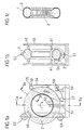
- Figures 1 to 3 show the wrapping of a ring-shaped body core, the outer contour of which corresponds to the inner contour of a tire, in a known manner with carcass threads 2.
- a winding core 1 is shown in a schematic cross-sectional view according to section IV-IV of Figure 1 in Figure 4.
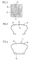
- the winding core 1 consists of two annular half-shells 12 and 13 formed concentrically with the winding core with cooperating annular clamping closure lugs 14 and 15.
- the half-shells, as shown in FIG. 2 are pressed in a known manner between an upper mold part 10 and a lower mold part 11 and then attached to it in a sealing manner on a centering ring 16, as shown in FIG. 4.
- the half-shell elements are fastened to one another in a sealing manner with their ring-shaped corresponding closure elements 14 and 15, respectively, with a positive fit.
- the outer contour of the shells of the core 1 formed by the two half-shells 12 and 13 corresponds to the inner contour of the tire to be manufactured.
- the half-shells are made of a thermoplastic material, the limit temperature for which the ins Plastic lies in the range between the operating temperature for the structure of the tire and the vulcanizing temperature.
- the half-shells are made from a thermoplastic, polymeric material whose glass transition temperature is above RT (room temperature) and which is thermally stable up to 200 ° C and can be processed by compression molding or injection molding or another suitable standard process.
- RT room temperature
- the centering ring is made of metal and has a circumferential centering surface on its radial inside.
- an inner layer is first placed in a known manner before the winding core is wound with a circumferential carcass thread 2 in the known manner shown in FIGS. 1a to 1c.
- the core is stored in a three-point bearing between the bearing disks 52 and 53 and a bearing belt 54, which is guided in a rotating manner via deflection rollers 55, 57 and a drive roller 58.
- a winding ring 51 is then built up around the cross-section of the core of Figure 4, as shown in Figures 1 a and b.
- the winding ring 51 is rotatably mounted between the bearing disks 61 about the cross section of the core 1.
- a coil 56 with a carcass thread 2 is fastened to the winding ring 51 in a known manner.
- the winding ring 51 is rotated in a known manner with a constant direction of rotation around the cross section of the core.
- the core 1 is slowly rotated about its axis via the bearing belt 54 at a speed which is precisely matched to the rotational speed of the winding ring 51.
- the carcass thread 2 is spiraled around with a precisely adjusted step size the structural core is wound, as shown in Figure 1c. In this way, several layers of carcass can be wound one above the other.
- cruciform arrangements of the carcass threads of different layers relative to one another are possible.
- a tire core 8 with a core profile 9 is placed concentrically on both sides of the core 1 outside the carcass.
- the carcass 2 is cut in a known manner in the middle of its axial extent in the radially lower region over the circumference and its ends are folded over radially outwards with the tire core 8 and the tire core profile 9. It is also conceivable to put the tire core 8 on before wrapping the carcass and after the carcass has been opened, to fold the carcass inwards around the core.
- the tire is covered in a known manner with belt 6, side stripes 5 and tread 7 and in the state built up on the core 1, together with the centering ring, temporarily stored until vulcanization.
- the centering ring can be used in a manner not shown to secure the tire by fastening in the storage area during intermediate storage to protect the tire.
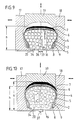
- the tire not previously removed from the core and from the centering ring is placed in a vulcanization press of a known type, consisting of conventional movable vulcanizing mold side parts 17 and 18 and radially movable profile segments distributed over the circumference between the side parts 19 of the mold trough centripedal design inserted.
- a vulcanization press of a known type, consisting of conventional movable vulcanizing mold side parts 17 and 18 and radially movable profile segments distributed over the circumference between the side parts 19 of the mold trough centripedal design inserted.
- the profile segments 19 form a closed circumferential ring.
- the centering ring 16 is opened an annular centering edge 20 of the one vulcanizing mold side part 17 is attached.
- the outer diameter of the centering edge 20 is precisely matched to the inner diameter of the centering ring 16.
- the side parts 18 and 17 move axially inwards relative to one another, the profile segments 19 are displaced radially inwards to produce the desired shape circle for the outer diameter of the tire.
- the molded parts 17, 18, the profile segments 19 and the centering ring 16 form a closed shape.
- a valve 21 in the centering ring 16 hot steam is introduced into the interior 22 of the tire core at a precisely predetermined pressure in a known manner, as in the case of conventional bellows for vulcanizing presses.
- the shell of the core 1 reaches a temperature which corresponds to the temperature for the transition to the plastic state, the shell becomes plastic.
- the shell expands due to the internal pressure in the interior 22 and thereby raises the assembled tire outwards into the molds 17, 18, 19.
- the area of the tread of the tire is raised from a height h from the lower centering ring edge of FIG. 5 to a height h 'raised. In this way, the tread is securely pressed into the profile contours of the profile segments 19.
- the tire is vulcanized in a conventional manner. After vulcanization, the superheated steam is drawn off either through the valve 21 or through one or more additional valves through the centering ring 16. Additional suction devices can be used for this. After opening the vulcanizing press, the tire with the centering ring is removed, the centering ring is detached from the half-shells 12 and 13 and the half-shells 12 and 13 are pulled out.
- centering ring 16 from two coaxial halves 16 ′, 16 ′′, which, as shown in FIG. 4a, are arranged axially next to one another for the core structure and are fastened to one another in a sealing manner.
- the halves 16 ', 16 are released and pulled out of the side of the tire.
- the centering ring halves of FIG. 4a are designed, for example, with an axially delimiting peripheral edge 63, against each of which a lip 62 of the elastic shell 13 or the shell 12 lies axially tight.
- the peripheral edge 63 is formed with its outer diameter so that it can be led out below the bead rubber 64.
- centering surfaces 16 are formed for centering the shells 12, 13.
- the core assembly shell halves 30 and 31 form with their inner contours the desired outer contour for the core 1 and thus for the inner contour of the desired tire.
- suitable filling bodies for example solid spheres made of glass, with a maximum diameter of 8 mm and with an average diameter of 0.5 to 5 mm, are produced to produce a particularly uniform, smooth Shell surface, preferably up to 2 mm, filled.
- the air in the core can escape through additional evacuation openings 35, the opening diameter of which is smaller than the diameter of the glass balls. If necessary, it can also be suctioned off with suitable known suction devices.
- the spheres 34 shown in greatly enlarged form in the figures, fill the entire interior 22 of the stretched sheath 32, so that a solid core is formed from the glass spheres 34 and the elastically stretched sheath 32 which holds the glass spheres 34 in the shape corresponding to the inner contour of the molds 30, 31 .
- the molds 30 and 31 are removed, and the tire in the manner already described for executing FIG. 4, as shown in FIG. 1, by placing an inner layer and by wrapping the carcass layers all round, by applying the tire cores and cutting open the carcass built up in the radially inner area, folding around the cores and by applying the side parts of the belt and the tread.
- the tire After appropriate intermediate storage, the tire, as shown in FIG. 9, is centered in a vulcanizing press of a known type. After the molds have been closed, hot steam at a predetermined pressure and temperature is additionally blown into the interior 22 of the core through valve openings 37 in the centering ring. Due to the resulting overpressure, the elastic sleeve 32 is stretched further outward and presses the built-up tire into the molded parts 17, 18, 19. As a result, the predetermined profile of the molded parts 19 is reliably transferred into the tread. When the internal and external temperature for the vulcanization is reached, the tire is vulcanized in a known manner.
- the superheated steam is first removed from the interior through valve opening 37. After opening the closure 36 of the filling openings 33, the balls are sucked out of the interior with the aid of suction pumps.
- the elastic cover collapses. The centering ring and the elastic cover can be easily pulled axially out of the tire.
Landscapes
- Engineering & Computer Science (AREA)
- Mechanical Engineering (AREA)
- Physics & Mathematics (AREA)
- Nonlinear Science (AREA)
- Moulds For Moulding Plastics Or The Like (AREA)
- Heating, Cooling, Or Curing Plastics Or The Like In General (AREA)
Applications Claiming Priority (2)
| Application Number | Priority Date | Filing Date | Title |
|---|---|---|---|
| DE4443049A DE4443049A1 (de) | 1994-12-05 | 1994-12-05 | Kern zum Aufbau eines Fahrzeugluftreifens |
| DE4443049 | 1994-12-05 |
Publications (3)
| Publication Number | Publication Date |
|---|---|
| EP0715947A2 true EP0715947A2 (fr) | 1996-06-12 |
| EP0715947A3 EP0715947A3 (fr) | 1996-12-27 |
| EP0715947B1 EP0715947B1 (fr) | 2001-05-23 |
Family
ID=6534814
Family Applications (1)
| Application Number | Title | Priority Date | Filing Date |
|---|---|---|---|
| EP95118997A Expired - Lifetime EP0715947B1 (fr) | 1994-12-05 | 1995-12-02 | Noyau pour la confection de pneumatiques |
Country Status (2)
| Country | Link |
|---|---|
| EP (1) | EP0715947B1 (fr) |
| DE (2) | DE4443049A1 (fr) |
Cited By (6)
| Publication number | Priority date | Publication date | Assignee | Title |
|---|---|---|---|---|
| EP0822047A1 (fr) * | 1996-08-01 | 1998-02-04 | Conception et Développement Michelin | Noyau destructible, utilisable notamment pour l'assemblage d'un pneu |
| EP0894614A1 (fr) * | 1997-07-31 | 1999-02-03 | PIRELLI COORDINAMENTO PNEUMATICI S.p.A. | Procédé pour la fabrication d'un bandage pneumatique pour roue de véhicule |
| US6336985B1 (en) | 1997-07-31 | 2002-01-08 | Pirelli Coordinamento Pneumatici S.P.A. | Method for making a tire for vehicle wheels |
| WO2007072511A1 (fr) | 2005-12-19 | 2007-06-28 | Pirelli Tyre S.P.A. | Procede et appareil permettant de fabriquer des pneus |
| FR2917326A1 (fr) * | 2007-06-15 | 2008-12-19 | Trelleborg Prodyn Soc Par Acti | Element de moulage d'une piece et procede de moulage correspondant |
| WO2018178586A1 (fr) * | 2017-03-30 | 2018-10-04 | Compagnie Generale Des Etablissements Michelin | Membrane et procédé de cuisson de pneumatique |
Citations (2)
| Publication number | Priority date | Publication date | Assignee | Title |
|---|---|---|---|---|
| DE1934018A1 (de) | 1969-07-04 | 1971-01-14 | Continental Gummi Werke Ag | Verfahren zum Aufbauen von Luftreifenkarkassen |
| EP0481805A2 (fr) | 1990-10-18 | 1992-04-22 | Bridgestone Corporation | Procédé de fabrication d'ébauches de carcasses et de pneus et pneus produits par ce procédé |
Family Cites Families (10)
| Publication number | Priority date | Publication date | Assignee | Title |
|---|---|---|---|---|
| US1687945A (en) * | 1925-05-08 | 1928-10-16 | Fisk Rubber Co | Tire building |
| DE598839C (de) * | 1932-01-15 | 1934-06-20 | Pirelli | Verfahren zur Herstellung von Kautschukhohlkoerpern mit Hilfe zerfliessbarer Kerne |
| US3183134A (en) * | 1962-04-03 | 1965-05-11 | Fairchild Hiller Corp | Tire building apparatus and method |
| NL6413789A (fr) * | 1964-11-27 | 1966-05-31 | ||
| DE1604528A1 (de) * | 1966-06-16 | 1970-11-12 | Bayer Ag | Formkern zur Herstellung von Hohlkoerpern aller Art |
| DE1934465A1 (de) * | 1969-07-08 | 1971-01-21 | Continental Gummi Werke Ag | Trommel oder Dorn zum Aufbauen von Luftreifen |
| DE2832566A1 (de) * | 1978-07-25 | 1980-02-07 | Bayer Ag | Verfahren zur herstellung von hohlkoerpern |
| JPS5675846A (en) * | 1979-11-24 | 1981-06-23 | Kobe Steel Ltd | Manufacture of beadless pneumatic tyre |
| US4474633A (en) * | 1982-06-03 | 1984-10-02 | The Goodyear Tire & Rubber Company | Method of manufacturing radial tires |
| FR2720326A1 (fr) * | 1994-05-27 | 1995-12-01 | Sedepro | Assemblage et vulcanisation de pneumatique. |
-
1994
- 1994-12-05 DE DE4443049A patent/DE4443049A1/de not_active Withdrawn
-
1995
- 1995-12-02 EP EP95118997A patent/EP0715947B1/fr not_active Expired - Lifetime
- 1995-12-02 DE DE59509284T patent/DE59509284D1/de not_active Expired - Fee Related
Patent Citations (2)
| Publication number | Priority date | Publication date | Assignee | Title |
|---|---|---|---|---|
| DE1934018A1 (de) | 1969-07-04 | 1971-01-14 | Continental Gummi Werke Ag | Verfahren zum Aufbauen von Luftreifenkarkassen |
| EP0481805A2 (fr) | 1990-10-18 | 1992-04-22 | Bridgestone Corporation | Procédé de fabrication d'ébauches de carcasses et de pneus et pneus produits par ce procédé |
Cited By (11)
| Publication number | Priority date | Publication date | Assignee | Title |
|---|---|---|---|---|
| EP0822047A1 (fr) * | 1996-08-01 | 1998-02-04 | Conception et Développement Michelin | Noyau destructible, utilisable notamment pour l'assemblage d'un pneu |
| AU720587B2 (en) * | 1996-08-01 | 2000-06-08 | Conception Et Developpement Michelin, S.A. | Destructible core for use, in particular, in the assembling of a tire |
| US6224808B1 (en) | 1996-08-01 | 2001-05-01 | Conception Et Developpement Michelin S.A. | Destructible core for use, in particular, in the assembling of a tire |
| EP0894614A1 (fr) * | 1997-07-31 | 1999-02-03 | PIRELLI COORDINAMENTO PNEUMATICI S.p.A. | Procédé pour la fabrication d'un bandage pneumatique pour roue de véhicule |
| US6336985B1 (en) | 1997-07-31 | 2002-01-08 | Pirelli Coordinamento Pneumatici S.P.A. | Method for making a tire for vehicle wheels |
| WO2007072511A1 (fr) | 2005-12-19 | 2007-06-28 | Pirelli Tyre S.P.A. | Procede et appareil permettant de fabriquer des pneus |
| US20100032873A1 (en) * | 2005-12-19 | 2010-02-11 | Maurizio Marchini | Method and Apparatus for Manufacturing Pneumatic Tyres |
| US8609007B2 (en) | 2005-12-19 | 2013-12-17 | Pirelli Tyre S.P.A. | Method and apparatus for manufacturing pneumatic tyres |
| FR2917326A1 (fr) * | 2007-06-15 | 2008-12-19 | Trelleborg Prodyn Soc Par Acti | Element de moulage d'une piece et procede de moulage correspondant |
| WO2018178586A1 (fr) * | 2017-03-30 | 2018-10-04 | Compagnie Generale Des Etablissements Michelin | Membrane et procédé de cuisson de pneumatique |
| FR3064526A1 (fr) * | 2017-03-30 | 2018-10-05 | Compagnie Generale Des Etablissements Michelin | Membrane et procede de cuisson de pneumatique |
Also Published As
| Publication number | Publication date |
|---|---|
| EP0715947A3 (fr) | 1996-12-27 |
| DE59509284D1 (de) | 2001-06-28 |
| EP0715947B1 (fr) | 2001-05-23 |
| DE4443049A1 (de) | 1996-06-13 |
Similar Documents
| Publication | Publication Date | Title |
|---|---|---|
| KR920003078B1 (ko) | 블래더리스 타이어 성형장치 | |
| EP4225567B1 (fr) | Presse chauffante et procédé de vulcanisation d'un pneu de véhicule dans ladite presse chauffante sous vide | |
| EP4225564B1 (fr) | Presse chauffante et procédé de vulcanisation d'un pneu de véhicule dans ladite presse chauffante sous vide | |
| DE68912960T2 (de) | Vorrichtung zum Reifenaufbau. | |
| DE1071325B (de) | Verfahren zum befestigen von metallkappen an luftfederbälgen | |
| EP4225566B1 (fr) | Presse chauffante et procédé de vulcanisation d'un pneu de véhicule dans ladite presse chauffante sous vide | |
| WO2021223822A1 (fr) | Presse chauffante et procédé de vulcanisation d'un pneumatique de véhicule dans ladite presse chauffante sous vide | |
| EP0715947B1 (fr) | Noyau pour la confection de pneumatiques | |
| EP2214880B1 (fr) | Appareil et procédé de vulcanisation et moulage de pneumatiques | |
| EP0182026B1 (fr) | Procédé et dispositif de vulcanisation de pneus | |
| DE19800289C2 (de) | Verfahren zur Herstellung von Luftreifen | |
| DE1579266B2 (de) | Vorrichtung zum bombieren einer auf einer hochschultertrommel aufgebauten reifenkarkasse | |
| EP1993819A1 (fr) | Tambour de confection de pneu | |
| US3674899A (en) | Process for curing pneumatic tires | |
| DE69402071T2 (de) | Verfahren zur herstellung eines reifens mit einer aus mindenstens einem fadengewebe oder seilgewebe hergestellten karkasse | |
| DE2644515C3 (de) | Verfahren zum Formen und Vulkanisieren eines Gürtel-Radial-Reifens | |
| DE10208613C1 (de) | Fahrzeugrad mit einem Notlaufstützkörper | |
| EP3869081B1 (fr) | Réservoir haute pression | |
| EP3939776B1 (fr) | Procédé de détermination d'un modèle de broche pour un enroulement de bande de roulement et système de production de pneumatiques | |
| WO2017220227A1 (fr) | Procédé de fabrication d'un bandage plein en caoutchouc, et bandage plein en caoutchouc fabriqué selon ledit procédé | |
| EP3957462A1 (fr) | Procédé de fabrication d'une demi-coquille | |
| DE10036999C2 (de) | Vulkanisiervorrichtung zum Vulkanisieren eines Kautschukartikels sowie Verfahren zum Formen und Vulkanisieren eines Kautschukartikels, insbesondere eines Fahrzeugreifens in einer Vulkanisiereinrichtung | |
| EP4417406B1 (fr) | Moule de chauffage de pneu | |
| DE19624766A1 (de) | Fahrzeugrad, Verfahren zur Herstellung eines Fahrzeugrades und Verwendung einer Felge eines Fahrzeugrads | |
| DE10359563A1 (de) | Vorrichtung und Verfahren zum Thermoformen von thermoplastischen, vorzugsweise folienartigen Halbzeugen |
Legal Events
| Date | Code | Title | Description |
|---|---|---|---|
| PUAI | Public reference made under article 153(3) epc to a published international application that has entered the european phase |
Free format text: ORIGINAL CODE: 0009012 |
|
| AK | Designated contracting states |
Kind code of ref document: A2 Designated state(s): DE FR GB IT |
|
| PUAL | Search report despatched |
Free format text: ORIGINAL CODE: 0009013 |
|
| AK | Designated contracting states |
Kind code of ref document: A3 Designated state(s): DE FR GB IT |
|
| 17P | Request for examination filed |
Effective date: 19970627 |
|
| 17Q | First examination report despatched |
Effective date: 19990427 |
|
| GRAG | Despatch of communication of intention to grant |
Free format text: ORIGINAL CODE: EPIDOS AGRA |
|
| GRAG | Despatch of communication of intention to grant |
Free format text: ORIGINAL CODE: EPIDOS AGRA |
|
| GRAH | Despatch of communication of intention to grant a patent |
Free format text: ORIGINAL CODE: EPIDOS IGRA |
|
| GRAH | Despatch of communication of intention to grant a patent |
Free format text: ORIGINAL CODE: EPIDOS IGRA |
|
| GRAA | (expected) grant |
Free format text: ORIGINAL CODE: 0009210 |
|
| AK | Designated contracting states |
Kind code of ref document: B1 Designated state(s): DE FR GB IT |
|
| REF | Corresponds to: |
Ref document number: 59509284 Country of ref document: DE Date of ref document: 20010628 |
|
| ITF | It: translation for a ep patent filed | ||
| GBT | Gb: translation of ep patent filed (gb section 77(6)(a)/1977) |
Effective date: 20010814 |
|
| ET | Fr: translation filed | ||
| REG | Reference to a national code |
Ref country code: GB Ref legal event code: IF02 |
|
| PLBE | No opposition filed within time limit |
Free format text: ORIGINAL CODE: 0009261 |
|
| STAA | Information on the status of an ep patent application or granted ep patent |
Free format text: STATUS: NO OPPOSITION FILED WITHIN TIME LIMIT |
|
| 26N | No opposition filed | ||
| PGFP | Annual fee paid to national office [announced via postgrant information from national office to epo] |
Ref country code: GB Payment date: 20041122 Year of fee payment: 10 |
|
| PG25 | Lapsed in a contracting state [announced via postgrant information from national office to epo] |
Ref country code: GB Free format text: LAPSE BECAUSE OF NON-PAYMENT OF DUE FEES Effective date: 20051202 |
|
| GBPC | Gb: european patent ceased through non-payment of renewal fee |
Effective date: 20051202 |
|
| PGFP | Annual fee paid to national office [announced via postgrant information from national office to epo] |
Ref country code: IT Payment date: 20081223 Year of fee payment: 14 |
|
| PGFP | Annual fee paid to national office [announced via postgrant information from national office to epo] |
Ref country code: FR Payment date: 20081212 Year of fee payment: 14 |
|
| PGFP | Annual fee paid to national office [announced via postgrant information from national office to epo] |
Ref country code: DE Payment date: 20081121 Year of fee payment: 14 |
|
| REG | Reference to a national code |
Ref country code: FR Ref legal event code: ST Effective date: 20100831 |
|
| PG25 | Lapsed in a contracting state [announced via postgrant information from national office to epo] |
Ref country code: FR Free format text: LAPSE BECAUSE OF NON-PAYMENT OF DUE FEES Effective date: 20091231 |
|
| PG25 | Lapsed in a contracting state [announced via postgrant information from national office to epo] |
Ref country code: DE Free format text: LAPSE BECAUSE OF NON-PAYMENT OF DUE FEES Effective date: 20100701 |
|
| PG25 | Lapsed in a contracting state [announced via postgrant information from national office to epo] |
Ref country code: IT Free format text: LAPSE BECAUSE OF NON-PAYMENT OF DUE FEES Effective date: 20091202 |