EP0716000A2 - Procédé pour déterminer la pente de la chaussée - Google Patents
Procédé pour déterminer la pente de la chaussée Download PDFInfo
- Publication number
- EP0716000A2 EP0716000A2 EP95118211A EP95118211A EP0716000A2 EP 0716000 A2 EP0716000 A2 EP 0716000A2 EP 95118211 A EP95118211 A EP 95118211A EP 95118211 A EP95118211 A EP 95118211A EP 0716000 A2 EP0716000 A2 EP 0716000A2
- Authority
- EP
- European Patent Office
- Prior art keywords
- determined
- driven axle
- value
- inclination
- hsp
- Prior art date
- Legal status (The legal status is an assumption and is not a legal conclusion. Google has not performed a legal analysis and makes no representation as to the accuracy of the status listed.)
- Granted
Links
Images


Classifications
-
- B—PERFORMING OPERATIONS; TRANSPORTING
- B60—VEHICLES IN GENERAL
- B60T—VEHICLE BRAKE CONTROL SYSTEMS OR PARTS THEREOF; BRAKE CONTROL SYSTEMS OR PARTS THEREOF, IN GENERAL; ARRANGEMENT OF BRAKING ELEMENTS ON VEHICLES IN GENERAL; PORTABLE DEVICES FOR PREVENTING UNWANTED MOVEMENT OF VEHICLES; VEHICLE MODIFICATIONS TO FACILITATE COOLING OF BRAKES
- B60T8/00—Arrangements for adjusting wheel-braking force to meet varying vehicular or ground-surface conditions, e.g. limiting or varying distribution of braking force
- B60T8/17—Using electrical or electronic regulation means to control braking
- B60T8/172—Determining control parameters used in the regulation, e.g. by calculations involving measured or detected parameters
-
- B—PERFORMING OPERATIONS; TRANSPORTING
- B60—VEHICLES IN GENERAL
- B60T—VEHICLE BRAKE CONTROL SYSTEMS OR PARTS THEREOF; BRAKE CONTROL SYSTEMS OR PARTS THEREOF, IN GENERAL; ARRANGEMENT OF BRAKING ELEMENTS ON VEHICLES IN GENERAL; PORTABLE DEVICES FOR PREVENTING UNWANTED MOVEMENT OF VEHICLES; VEHICLE MODIFICATIONS TO FACILITATE COOLING OF BRAKES
- B60T2210/00—Detection or estimation of road or environment conditions; Detection or estimation of road shapes
- B60T2210/20—Road shapes
- B60T2210/22—Banked curves
Definitions
- the invention relates to a method for determining the road inclination according to the preamble of claim 1, as it is known for example from the patent US 43 52 405.
- an inclination of the road is detected by an inclination sensor and evaluated in an evaluation unit.
- the detection of the inclination of the carriageway in the direction of travel serves to select the operating position of a braking system of the vehicle in such a way that the downhill forces are compensated for by a corresponding braking torque of the braking system.
- This device requires complex sensors to determine the inclination angle of the road in the direction of travel. Furthermore, this sensor system is subject to the ongoing fluctuations in the vehicle body and the vibrations of the vehicle, as a result of which the measuring accuracy is impaired. Except for vehicles with air suspension, an inclination sensor system also does not take into account the changing inclination of the bodywork with respect to the roadway due to the different loading of the vehicle.
- the object of the invention is to determine the inclination of the road in the direction of travel of the vehicle without additional sensors, from signals recorded in the vehicle for other purposes.
- a free-rolling state of the at least one driven axle of the vehicle is recognized at least once.
- the wheels of the driven axle also roll without slipping.
- the difference in speed between the wheel speed of a driven axle and the wheel speed of a non-driven axle is determined.
- the value of the deceleration i.e. the vehicle deceleration, is determined.
- a drive state of the driven axle recognized as stationary is then detected at least once.
- the differential speed between the driven axle and the non-driven axle as well as the braking of the vehicle is determined.
- the braking value is usually negative, which means that the vehicle is accelerated.
- the difference in the differential speeds that were determined during these two driving conditions is a measure of the driving force.
- the specific time interval between the detection when the drive wheels are in a free-rolling state and the stationary drive state of the drive wheels ensures that the inclination of the road has not changed significantly.
- the value of an inclination constant is determined from the determined values of the differential speeds and the decelerations. As soon as a steady state of the driven axle is ascertained, the inclination constant can be used to determine the road inclination from the values of the differential speed and braking that are then determined.
- the state of freely rolling drive wheels usually occurs when a gear change takes place and for this purpose the Clutch is actuated. The frictional connection between the motor and the driven axle is then interrupted. Since the upshift breaks, ie the gear changes at which a higher gear is engaged, are particularly suitable for evaluation, the state of freely rolling drive wheels is also referred to as upshift breaks below. Most of the upshift breaks are followed by an acceleration phase, so that a stationary drive state often arises immediately after an upshift break.
- the braking is determined from the change in time of the wheel speeds. According to this embodiment of the invention, the detection of the wheel speeds is sufficient as the only measured variables for carrying out the invention.
- a value for the inclination constant is first determined for each journey before the inclination of the roadway can be determined.
- a new value for the inclination constant is determined at every possible opportunity to determine the inclination constant.
- the mean value from the values of the inclination constant determined during a journey is used as the inclination constant.
- a pressure base value is determined on the basis of the last determined value for the inclination of the roadway if a predetermined holding time has not been exceeded between the time of determining the value for the inclination and the actuation.
- the Pressure base value which may also have a negative amount, is added to the brake pressure setpoint resulting from the position of the brake pedal at least when the inclination represents a gradient of the road.
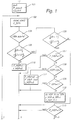
- An initialization is carried out in step 101.
- the values of all pointers F_ are reset to zero.
- the value of the road inclination in the direction of travel p is reset to zero.
- the value is read from a memory.
- This value can either be predefined as a fixed value or can be selected as a function of vehicle parameters and variables representing the driving state.
- the drag coefficient of the vehicle is known and its speed can be derived, for example, from the wheel speeds, so that the share of drag in driving resistance can be determined at least approximately. The same applies to the influences of the rotating masses. It can also be determined experimentally on a calibration route with a known lane inclination, for example one level. This initialization takes place at the beginning of each journey, since essential factors on the vehicle can change, for example the loading.
- step 102 impermissible driving conditions are filtered out. From the wheel speed signals, cornering is recognized, for example on the basis of a vehicle-side comparison of the wheel speeds, and is excluded from the further method. It is checked whether the values of the differential speed ds and the braking z determined in this cycle can be assigned to a steady state. In this case, the pointer F_SPh is set to "1". Otherwise it is set to "0".
- the actuation of the brake can also be regarded as an impermissible driving state. This is necessary if the braking torques resulting from the actuation of the brake and thus the braking torques resulting therefrom cannot be determined with sufficient accuracy. However, if the deceleration resulting from the actuation of the brake is known with sufficient accuracy, then the method can also be carried out when the brake is applied.
- step 104 it is checked whether the time that has elapsed after the end of the last brake application is greater than one second. This serves to exclude signals influenced by braking processes.
- steps 105 to 115 the upshifts and the stationary states are determined and the corresponding values of the required size are determined.
- steps 116 to 121 the value of the inclination constant mk is determined from this by averaging with previously determined values of the inclination constant.
- Steps 122 to 124 serve to determine the inclination of the roadway as soon as a value for the inclination constant is available.
- step 105 it is checked whether there is a rapid increase in the differential speed ds and at the same time a rapid increase in the deceleration dz.
- the time derivative of these two quantities must therefore be determined numerically. For this purpose, for example, the difference between the current value of the differential speed ds and the value of the differential speed ds' is calculated in the previous determination and the quotient of the difference is formed with the time elapsed between the two determinations of the differential speed. The same procedure can be used for braking z. The values obtained are compared with predetermined upper threshold values. For the time derivative of the differential speed - which is present in the form of a dimensionless variable in the description of FIG.
- the time derivative of which is therefore in the unit 1 / s - the threshold is, for example, 0.02 * 1 / s.
- the threshold value for the time derivative of the braking has the unit m / s3 and, for example, a value of 1.5 m / s3. It should be noted that both the deceleration and differential speed parameters have a relevant sign and therefore the reduction in the amount of a value with a negative sign is referred to as an increase.
- step 110 If the upper threshold values for both the increase in the differential speed and the increase in the braking are exceeded, the possible start of an upshift pause is inferred and, in accordance with step 110, the pointer F_HSP which indicates an upshift pause is set, that is, it takes the value "1" at.
- the time counter t_HSP for the duration of the upshift pause or the freely rolling state of the drive axis is also reset to "0". The process then jumps to step 116.
- step 106 If it is determined in step 105 that the threshold values have not been exceeded, it is checked in step 106 whether there is a rapid reduction (a steep drop) in the braking and the differential speed. For this purpose, it is checked whether the time derivative of the differential speed ds and the time derivative of the deceleration z fall below predetermined lower threshold values. It should be noted that because of the sign, a rapid decrease corresponds to an increase in the amount, provided the lower threshold values have a negative sign.
- the lower threshold value for the time derivative of the differential speed ds is, for example, -0.01 1 / s, the lower threshold value for the deceleration z, for example, -1 m / s3.
- step 113 There it is checked whether the start of an upshift pause was determined by checking whether the pointer F_HSP has the value 1. Only if a start of an upshift pause has been determined before the end can the steep drop in the braking z and the differential speed ds be the end of an upshift pause. If the pointer F_HSP does not have the value "1", the process jumps to step 116. Otherwise there is actually a usable upshift pause and in step 115 the calculation of the differential speed ds_HSP for the freely rolling state of the driven axis determined.
- ds_HSP_V (ds_HSP * [n_HSP-1] + ds_HSP) / n_HSP, where N_HSP is the number of usable upshift pauses determined during the current trip, which is also incremented in this step before the calculation.
- the pointer F_HSP_V is reset to "0"
- the pointer F_mk for determining the inclination constant mk is set to "1”
- the counter t_mk is reset to "0”. The process then jumps to step 116.
- the speed difference ds_HSP determined in this way is a measure of the speed differences between the non-driven axis and the driven axis. It can be used as the basis for speed adjustment, for example for tire pressure determination or an anti-lock braking system. It is continuously updated and, since it is based only on measured values recorded during freely rolling conditions, is a very good measure of the speed difference due to different wheel circumferences.
- step 106 If it is determined in step 106 that there is no steep drop in the braking z and the differential speed ds, a plausibility check is started in steps 107 to 109 and 111 to 112. For this purpose, step 107 checks whether the pointer F_HSP was set to "1" in a previous cycle, that is to say whether the start of an upshift pause was determined. If this is not the case, the process jumps to step 116. Otherwise it is checked in step 108 whether the time counter t_HSP has exceeded a limit value of, for example, 2s for the duration of the upshift pause since the pointer F_HSP was set.
- step 111 the pointers F_HSP and F_HSP_V and the time counter t_HSP are reset to "0" in step 111, since such a long duration of an upshift pause or a freely rolling state of the wheels is not plausible. After step 111, a jump is made to step 116.
- step 109 checks whether there is a steady state, that is to say whether the pointer F_SPh is set to "1". If this is not the case, the process jumps to step 116.
- the deceleration z_SPh and the differential speed ds_SPh were determined in step 102 for the same point in time. The process then jumps to step 116.
- step 116 it is checked whether the pointer F_mk for the calculation of the inclination constant is set to "1". If this is not the case, the process jumps to step 122. Otherwise, it is checked in step 117 whether the time counter t_mk has not yet exceeded the predetermined time interval dt_max, for example 7 s. Instead of a fixed time threshold, it can also be specified as a travel threshold or as a function of the speed.
- step 118 the pointer F_mk and the time counter t_mk are therefore reset to "0" and the system jumps to step 122.
- the inclination constant mk can be determined if there is a steady state. For this purpose, it is checked in step 119 whether the pointer F_SPh is set to "1". If this is not the case, then there is currently no steady state and it has jumped to step 122. Otherwise, a check of the measured values of the steady state takes place in step 120 in order to rule out inadmissible values or values which impair the measuring accuracy. The cases of insufficient drive forces and the cases of excessive deceleration z or excessive differential speed ds_SPh are excluded. The last two criteria serve to rule out conditions in which the hypothesis of linear tire characteristics can no longer be justified.
- a new value for the inclination constant mk is obtained in step 121 by averaging with values of the inclination constants that may have already been determined during the present journey mk calculated.
- the value of the inclination constant mk_a from the current values of the deceleration z and the differential speed ds according to the equation mk_a [ds_SPh - ds_HSP] / [z_SPh - z_HSP] determined.
- the braking values are then limited to an interval of, for example, 0.005 to 0.12 for reasons of plausibility.
- the pointer F_p is set to "1", that is, the determination of the inclination p of the road in the direction of travel is made possible. Step 122 follows.
- the inclination p is a dimensionless quantity and corresponds to the tangent of the inclination angle of the road.
- a negative slope corresponds to a slope and a positive slope corresponds to a slope of the road.
- the system then jumps to step 102 and a new cycle begins.
- the value of the inclination determined last can be used, for example, to determine a pressure base value, which has a negative sign on an incline, which is added to the pressure setpoint specified by the position of the accelerator pedal. This is the controlled one Brake pressure better adapted to a target deceleration predetermined by the position of the brake pedal.
- a current value of the road inclination p can subsequently be determined during the journey after each stationary phase that has been detected.
- the stationary phases occur at driving intervals of approximately 0.5 to a few seconds.
- a stationary phase is recognized for the last time when the driver switches his foot from the accelerator pedal to the brake pedal, i.e. immediately before the brake is applied. So there is always a current value for the road gradient.
- Fig. 2 shows the course of the three curves vehicle speed in km / h, differential speed (dimensionless) and braking in m / s2 for a starting process from a standing position on the plane over time t.
- the curve shown at the top shows the course of the braking z
- the curve for the differential speed ds is shown in the middle
- the curve for the vehicle speed v is shown below.
- the differential speed is defined as a dimensionless quantity so that it is independent of the vehicle speed.
- the wheel speed ⁇ is determined for a driven axle, for example the wheel speed ⁇ _HA of the rear axle, and for a non-driven axle, for example the wheel speed ⁇ _VA of the front axle.
- the first upshift pause due to the strongly fluctuating values of the speed difference ds cannot be used to determine the Inclination constants are used.
- the start of the upshift pauses can be easily recognized by the steep increase A1 or A2 of the braking z.
- Ab1 or Ab2 the end of the upshift breaks HSP_1 and HSP_2.
- HSP_2 a freely rolling state of the drive axle during which the differential speed ds and deceleration z have a stationary phase is determined at time S1, so that these values are used as differential speed ds_HSP and deceleration z_HSP to calculate the inclination constant mk.
- a stationary drive state is determined at time S2 with the differential speed ds_SPH and the deceleration z_SPh.
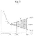
- a value of a quantity is associated with a steady state over time is described below with the aid of the deceleration z and is shown in FIG. 4.
- the slope of the straight line is, for example, 0.5 m / s3
- FIG. 3 shows how the inclination constant results from the measured values obtained during the upshift pause HSP_2 and the steady state S2.
- the deceleration z is plotted as the abscissa and the differential speed ds as the ordinate.
- the inclination constant corresponds to the slope of the straight line which connects the points measured at times S1 and S2 with the coordinates (z_HSP, ds_HSP) or (z_SPh, ds_SPh).
Landscapes
- Engineering & Computer Science (AREA)
- Transportation (AREA)
- Mechanical Engineering (AREA)
- Regulating Braking Force (AREA)
- Control Of Transmission Device (AREA)
Applications Claiming Priority (2)
| Application Number | Priority Date | Filing Date | Title |
|---|---|---|---|
| DE4443522 | 1994-12-07 | ||
| DE4443522A DE4443522C2 (de) | 1994-12-07 | 1994-12-07 | Verfahren zur Bestimmung der Fahrbahnneigung |
Publications (3)
| Publication Number | Publication Date |
|---|---|
| EP0716000A2 true EP0716000A2 (fr) | 1996-06-12 |
| EP0716000A3 EP0716000A3 (fr) | 1998-11-04 |
| EP0716000B1 EP0716000B1 (fr) | 2002-01-09 |
Family
ID=6535136
Family Applications (1)
| Application Number | Title | Priority Date | Filing Date |
|---|---|---|---|
| EP95118211A Expired - Lifetime EP0716000B1 (fr) | 1994-12-07 | 1995-11-20 | Procédé pour déterminer la pente de la chaussée |
Country Status (4)
| Country | Link |
|---|---|
| US (1) | US5797109A (fr) |
| EP (1) | EP0716000B1 (fr) |
| JP (1) | JP2676687B2 (fr) |
| DE (1) | DE4443522C2 (fr) |
Cited By (4)
| Publication number | Priority date | Publication date | Assignee | Title |
|---|---|---|---|---|
| WO1999001321A1 (fr) * | 1997-07-02 | 1999-01-14 | Robert Bosch Gmbh | Procede et dispositif pour le reglage d'une grandeur representative du mouvement d'un vehicule |
| WO2000048882A1 (fr) * | 1999-02-18 | 2000-08-24 | Continental Teves Ag & Co. Ohg | Procede et dispositif pour la surveillance de plusieurs capteurs detectant un processus, en particulier pour un systeme de programme electronique de stabilite pour vehicules |
| US6386019B1 (en) | 1997-10-17 | 2002-05-14 | Continental Teves Ag & Co., Ohg | Method and device for detecting an externally caused variable driving or braking a vehicle, especially such a moment |
| WO2010139493A1 (fr) * | 2009-06-03 | 2010-12-09 | Zf Friedrichshafen Ag | Procédé d'étalonnage d'un capteur d'inclinaison |
Families Citing this family (18)
| Publication number | Priority date | Publication date | Assignee | Title |
|---|---|---|---|---|
| DE4444650C2 (de) * | 1994-12-15 | 1996-09-26 | Daimler Benz Ag | Verfahren zur Bestimmung von Dauerbremsanteilen bei einem Fahrzeug |
| DE19513509C2 (de) * | 1995-04-10 | 2000-07-13 | Daimler Chrysler Ag | Verfahren zur Bestimmung des Verhältnisses zwischen der Masse eines Fahrzeugzuges und der Masse des Zugfahrzeugs |
| DE19821618C1 (de) | 1998-05-15 | 1999-09-16 | Daimler Chrysler Ag | Verfahren zum Erkennen von seitlich geneigten Kurven |
| DE19821617C1 (de) | 1998-05-15 | 1999-09-30 | Daimler Chrysler Ag | Verfahren und Vorrichtung zur Messung des Neigungswinkels in seitlich geneigten Kurven und deren Verwendung |
| DE10019137A1 (de) * | 2000-04-18 | 2001-10-25 | Bosch Gmbh Robert | Schlupfregelsystem für ein Fahrzeug |
| JP4076740B2 (ja) * | 2001-06-22 | 2008-04-16 | 住友ゴム工業株式会社 | 路面勾配判定装置および方法、ならびに勾配判定のプログラム |
| DE10135825B4 (de) * | 2001-07-23 | 2006-04-06 | Bayerische Motoren Werke Ag | Elektronisches Steuergerät zur Gangwechselsteuerung von automatisch schaltenden Getrieben für Kraftfahrzeuge |
| DE10144302A1 (de) * | 2001-09-10 | 2003-06-12 | Knorr Bremse Systeme | Bremsvorrichtung für Fahrzeuge, die eine Betriebsbremsanlage und eine Dauerbremsanlage aufweisen |
| DE10145118B4 (de) * | 2001-09-13 | 2007-06-14 | Knorr-Bremse Systeme für Nutzfahrzeuge GmbH | Bremsdruckregelungsverfahren |
| DE10350782B4 (de) * | 2003-10-30 | 2016-06-30 | Robert Bosch Gmbh | Verfahren und Vorrichtung zur Ermittlung einer die Längsneigung einer Fahrbahn repräsentierenden Längsneigungsgröße |
| JP2005186813A (ja) * | 2003-12-25 | 2005-07-14 | Fuji Heavy Ind Ltd | 車両用運転支援装置 |
| JP4541839B2 (ja) * | 2004-11-05 | 2010-09-08 | 三菱電機株式会社 | 路面の傾斜判定システム |
| US7757406B2 (en) * | 2007-05-29 | 2010-07-20 | Sepehr Khashaei | Vehicle travel grade indicator (VTGI) |
| US8242802B2 (en) * | 2009-04-14 | 2012-08-14 | Via Technologies, Inc. | Location-based bus termination for multi-core processors |
| US7843225B2 (en) * | 2009-04-14 | 2010-11-30 | Via Technologies, Inc. | Protocol-based bus termination for multi-core processors |
| DE102009045255A1 (de) * | 2009-10-01 | 2011-04-07 | Zf Friedrichshafen Ag | Verfahren zum Kalibrieren eines Neigungssensors |
| WO2016035036A2 (fr) * | 2014-09-03 | 2016-03-10 | Mansourian Arash | Dispositif de mesure de la pente d'une surface avec nivellement de trajet |
| KR101936769B1 (ko) | 2017-07-13 | 2019-01-11 | 한국건설기술연구원 | 차량데이터와 영상데이터를 활용한 노면상태 측정 시스템 및 그 방법 |
Citations (1)
| Publication number | Priority date | Publication date | Assignee | Title |
|---|---|---|---|---|
| US4352405A (en) | 1979-04-10 | 1982-10-05 | Labavia - S.G.E. | Control devices for speed reducers |
Family Cites Families (8)
| Publication number | Priority date | Publication date | Assignee | Title |
|---|---|---|---|---|
| DE3334719A1 (de) * | 1983-09-26 | 1985-04-04 | Wabco Westinghouse Fahrzeugbremsen GmbH, 3000 Hannover | Einrichtung zur ermittlung der fahrbahnsteigung |
| DE3933652A1 (de) * | 1989-10-09 | 1991-04-11 | Bosch Gmbh Robert | Antiblockierregelsystem und antriebsschlupfregelsystem |
| DE4010073A1 (de) * | 1990-03-29 | 1991-10-02 | Wabco Westinghouse Fahrzeug | Einrichtung zur bergfahrt-erkennung |
| US5132906A (en) * | 1990-06-11 | 1992-07-21 | Ford Motor Company | Road surface friction and hill slope estimator |
| US5333944A (en) * | 1991-08-06 | 1994-08-02 | Toyota Jidosha Kabushiki Kaisha | Electrically controlled vehicle brake system having means for controlling braking based on detected actual braking effect and determined target value |
| DE4308128C2 (de) * | 1993-03-15 | 1998-07-23 | Telefunken Microelectron | Verfahren zur Bestimmung der Fahrbahn-Längsneigung während der ungebremsten Fahrt eines Kraftfahrzeugs |
| JP3064759B2 (ja) * | 1993-09-28 | 2000-07-12 | 株式会社日立製作所 | 車両の周囲を監視する装置、車両の運転支援システムおよび運転支援装置 |
| US5446658A (en) * | 1994-06-22 | 1995-08-29 | General Motors Corporation | Method and apparatus for estimating incline and bank angles of a road surface |
-
1994
- 1994-12-07 DE DE4443522A patent/DE4443522C2/de not_active Expired - Lifetime
-
1995
- 1995-11-20 EP EP95118211A patent/EP0716000B1/fr not_active Expired - Lifetime
- 1995-12-06 JP JP7347455A patent/JP2676687B2/ja not_active Expired - Lifetime
- 1995-12-07 US US08/568,447 patent/US5797109A/en not_active Expired - Lifetime
Patent Citations (1)
| Publication number | Priority date | Publication date | Assignee | Title |
|---|---|---|---|---|
| US4352405A (en) | 1979-04-10 | 1982-10-05 | Labavia - S.G.E. | Control devices for speed reducers |
Cited By (8)
| Publication number | Priority date | Publication date | Assignee | Title |
|---|---|---|---|---|
| WO1999001321A1 (fr) * | 1997-07-02 | 1999-01-14 | Robert Bosch Gmbh | Procede et dispositif pour le reglage d'une grandeur representative du mouvement d'un vehicule |
| US6386019B1 (en) | 1997-10-17 | 2002-05-14 | Continental Teves Ag & Co., Ohg | Method and device for detecting an externally caused variable driving or braking a vehicle, especially such a moment |
| WO2000048882A1 (fr) * | 1999-02-18 | 2000-08-24 | Continental Teves Ag & Co. Ohg | Procede et dispositif pour la surveillance de plusieurs capteurs detectant un processus, en particulier pour un systeme de programme electronique de stabilite pour vehicules |
| US6594563B1 (en) | 1999-02-18 | 2003-07-15 | Continental Teves, Ag & Co. Ohg | Method and device for monitoring a plurality of sensors detecting a process, notably for an ESP system for vehicles |
| WO2010139493A1 (fr) * | 2009-06-03 | 2010-12-09 | Zf Friedrichshafen Ag | Procédé d'étalonnage d'un capteur d'inclinaison |
| CN102458955A (zh) * | 2009-06-03 | 2012-05-16 | Zf腓德烈斯哈芬股份公司 | 用于校验倾斜度传感器的方法 |
| US8386123B2 (en) | 2009-06-03 | 2013-02-26 | Zf Friedrichshafen Ag | Method for calibrating a slope sensor |
| CN102458955B (zh) * | 2009-06-03 | 2014-09-10 | Zf腓德烈斯哈芬股份公司 | 用于校验倾斜度传感器的方法 |
Also Published As
| Publication number | Publication date |
|---|---|
| JPH08254425A (ja) | 1996-10-01 |
| US5797109A (en) | 1998-08-18 |
| EP0716000A3 (fr) | 1998-11-04 |
| DE4443522A1 (de) | 1996-06-13 |
| DE4443522C2 (de) | 1999-11-25 |
| JP2676687B2 (ja) | 1997-11-17 |
| EP0716000B1 (fr) | 2002-01-09 |
Similar Documents
| Publication | Publication Date | Title |
|---|---|---|
| EP0716000B1 (fr) | Procédé pour déterminer la pente de la chaussée | |
| DE69817698T2 (de) | Verschleisszustandserfassungsvorrichtung für Reifen und Verfahren | |
| EP0630786B1 (fr) | Procédé et circuit pour relever la valeur de frottement | |
| DE4218034B4 (de) | Verfahren zur Bestimmung des Kraftschlußpotentials eines Kraftfahrzeuges | |
| EP0563596B1 (fr) | Procédé pour déterminer des valeurs de référence de freinage | |
| EP1597124B1 (fr) | Procede et dispositif d'estimation assistee par ordinateur de la masse d'un vehicule, notamment d'un vehicule industriel | |
| DE69729250T2 (de) | Gerät zur feststellung eines druckverlustes in einem reifen | |
| EP0393375A2 (fr) | Procédé pour déterminer le patinage de roue de différentes roues d'un véhicule | |
| WO2003040652A1 (fr) | Procede et dispositif pour determiner l'inclinaison geometrique d'un vehicule a moteur | |
| EP1628862A1 (fr) | Procede et dispositif pour determiner une grandeur de frottement representant les frottements qui agissent entre une chaussee et des pneumatiques de vehicule | |
| DE19821617C1 (de) | Verfahren und Vorrichtung zur Messung des Neigungswinkels in seitlich geneigten Kurven und deren Verwendung | |
| EP1005423A1 (fr) | Procede et dispositif permettant de determiner la vitesse de reference d'un vehicule | |
| EP1045783B1 (fr) | Dispositif et procede pour limiter la vitesse de roulement en arriere d'un vehicule automobile | |
| DE102007045998A1 (de) | Technik zur Verbesserung der Fahrstabilität eines Kraftfahrzeugs auf Basis einer Massebestimmung | |
| DE102018200180A1 (de) | Verfahren zur Ermittlung des Reibwerts zwischen einem Fahrzeugrad und der Fahrbahn | |
| DE69715134T2 (de) | Verfahren und Ausrüstung zum Erkennen eines Reifens mit zumindest teilweisem Druckverlust an einem Kraftfahtzeug. | |
| DE102005015725A1 (de) | Bestimmen des Aktivierungszeitpunkts einer automatischen Haltefunktion | |
| DE19537791C2 (de) | Verfahren und Vorrichtung zur Ermittlung der Fahrgeschwindigkeit eines Kraftfahrzeuges | |
| DE10350782B4 (de) | Verfahren und Vorrichtung zur Ermittlung einer die Längsneigung einer Fahrbahn repräsentierenden Längsneigungsgröße | |
| DE102008003206B4 (de) | Verfahren und Vorrichtung zum Berechnen der Achslast nicht lastsensierter Achsen eines Fahrzeugs | |
| EP0859712A1 (fr) | Procede et dispositif de regulation d'une quantite de mouvement representant le mouvement du vehicule | |
| EP1255653B1 (fr) | Procede et dispositif de detection d'une perte de pression sur les pneumatiques d'un vehicule, avec controle de plausibilite | |
| DE60314727T2 (de) | Ein Verfahren und ein Computer für eine Abschätzung der Reibung zwischen Reifen und Strasse | |
| DE3917976A1 (de) | Verfahren zur bestimmung der fahrzeuggeschwindigkeit bei einem kraftfahrzeug mit heckantrieb | |
| EP1240038B1 (fr) | Procede et dispositif permettant de detecter une perte de pression dans les pneus d'un vehicule a moteur |
Legal Events
| Date | Code | Title | Description |
|---|---|---|---|
| PUAI | Public reference made under article 153(3) epc to a published international application that has entered the european phase |
Free format text: ORIGINAL CODE: 0009012 |
|
| AK | Designated contracting states |
Kind code of ref document: A2 Designated state(s): FR GB IT NL SE |
|
| RAP1 | Party data changed (applicant data changed or rights of an application transferred) |
Owner name: DAIMLER-BENZ AKTIENGESELLSCHAFT |
|
| PUAL | Search report despatched |
Free format text: ORIGINAL CODE: 0009013 |
|
| AK | Designated contracting states |
Kind code of ref document: A3 Designated state(s): FR GB IT NL SE |
|
| 17P | Request for examination filed |
Effective date: 19981010 |
|
| RAP1 | Party data changed (applicant data changed or rights of an application transferred) |
Owner name: DAIMLERCHRYSLER AG |
|
| 17Q | First examination report despatched |
Effective date: 20000317 |
|
| GRAG | Despatch of communication of intention to grant |
Free format text: ORIGINAL CODE: EPIDOS AGRA |
|
| GRAG | Despatch of communication of intention to grant |
Free format text: ORIGINAL CODE: EPIDOS AGRA |
|
| GRAH | Despatch of communication of intention to grant a patent |
Free format text: ORIGINAL CODE: EPIDOS IGRA |
|
| GRAH | Despatch of communication of intention to grant a patent |
Free format text: ORIGINAL CODE: EPIDOS IGRA |
|
| GRAA | (expected) grant |
Free format text: ORIGINAL CODE: 0009210 |
|
| REG | Reference to a national code |
Ref country code: GB Ref legal event code: IF02 |
|
| AK | Designated contracting states |
Kind code of ref document: B1 Designated state(s): FR GB IT NL SE |
|
| GBT | Gb: translation of ep patent filed (gb section 77(6)(a)/1977) |
Effective date: 20020409 |
|
| ET | Fr: translation filed | ||
| PLBE | No opposition filed within time limit |
Free format text: ORIGINAL CODE: 0009261 |
|
| STAA | Information on the status of an ep patent application or granted ep patent |
Free format text: STATUS: NO OPPOSITION FILED WITHIN TIME LIMIT |
|
| 26N | No opposition filed | ||
| NLT1 | Nl: modifications of names registered in virtue of documents presented to the patent office pursuant to art. 16 a, paragraph 1 |
Owner name: DAIMLER AG |
|
| REG | Reference to a national code |
Ref country code: FR Ref legal event code: CD Ref country code: FR Ref legal event code: CA |
|
| REG | Reference to a national code |
Ref country code: NL Ref legal event code: SD Effective date: 20101102 |
|
| REG | Reference to a national code |
Ref country code: GB Ref legal event code: 732E Free format text: REGISTERED BETWEEN 20101118 AND 20101124 |
|
| REG | Reference to a national code |
Ref country code: FR Ref legal event code: TP |
|
| PGFP | Annual fee paid to national office [announced via postgrant information from national office to epo] |
Ref country code: SE Payment date: 20141120 Year of fee payment: 20 Ref country code: GB Payment date: 20141120 Year of fee payment: 20 |
|
| PGFP | Annual fee paid to national office [announced via postgrant information from national office to epo] |
Ref country code: NL Payment date: 20141120 Year of fee payment: 20 Ref country code: FR Payment date: 20141118 Year of fee payment: 20 |
|
| PGFP | Annual fee paid to national office [announced via postgrant information from national office to epo] |
Ref country code: IT Payment date: 20141121 Year of fee payment: 20 |
|
| REG | Reference to a national code |
Ref country code: NL Ref legal event code: MK Effective date: 20151119 |
|
| REG | Reference to a national code |
Ref country code: GB Ref legal event code: PE20 Expiry date: 20151119 |
|
| PG25 | Lapsed in a contracting state [announced via postgrant information from national office to epo] |
Ref country code: GB Free format text: LAPSE BECAUSE OF EXPIRATION OF PROTECTION Effective date: 20151119 |