EP0716018B1 - Machine de nouage à bout unique - Google Patents
Machine de nouage à bout unique Download PDFInfo
- Publication number
- EP0716018B1 EP0716018B1 EP95118360A EP95118360A EP0716018B1 EP 0716018 B1 EP0716018 B1 EP 0716018B1 EP 95118360 A EP95118360 A EP 95118360A EP 95118360 A EP95118360 A EP 95118360A EP 0716018 B1 EP0716018 B1 EP 0716018B1
- Authority
- EP
- European Patent Office
- Prior art keywords
- string
- spool
- pins
- pliers
- machine according
- Prior art date
- Legal status (The legal status is an assumption and is not a legal conclusion. Google has not performed a legal analysis and makes no representation as to the accuracy of the status listed.)
- Expired - Lifetime
Links
- 230000033001 locomotion Effects 0.000 claims abstract description 20
- 230000002093 peripheral effect Effects 0.000 claims description 21
- 238000004804 winding Methods 0.000 claims description 8
- 230000015572 biosynthetic process Effects 0.000 claims description 6
- 230000008878 coupling Effects 0.000 claims description 6
- 238000010168 coupling process Methods 0.000 claims description 6
- 238000005859 coupling reaction Methods 0.000 claims description 6
- 238000011084 recovery Methods 0.000 claims description 5
- 230000003042 antagnostic effect Effects 0.000 claims description 4
- 230000000452 restraining effect Effects 0.000 claims 3
- 230000000295 complement effect Effects 0.000 claims 1
- 230000001360 synchronised effect Effects 0.000 claims 1
- 241001237745 Salamis Species 0.000 description 5
- 235000013351 cheese Nutrition 0.000 description 5
- 235000013305 food Nutrition 0.000 description 5
- 235000015175 salami Nutrition 0.000 description 5
- 235000013580 sausages Nutrition 0.000 description 4
- 235000013372 meat Nutrition 0.000 description 3
- 235000015277 pork Nutrition 0.000 description 2
- 238000002360 preparation method Methods 0.000 description 2
- 240000002129 Malva sylvestris Species 0.000 description 1
- 235000006770 Malva sylvestris Nutrition 0.000 description 1
- 239000004744 fabric Substances 0.000 description 1
- 239000002421 finishing Substances 0.000 description 1
- 239000011810 insulating material Substances 0.000 description 1
- 238000004519 manufacturing process Methods 0.000 description 1
- 238000012856 packing Methods 0.000 description 1
- 230000001105 regulatory effect Effects 0.000 description 1
- 230000000284 resting effect Effects 0.000 description 1
- 238000009958 sewing Methods 0.000 description 1
- 239000000126 substance Substances 0.000 description 1
Images




Classifications
-
- B—PERFORMING OPERATIONS; TRANSPORTING
- B65—CONVEYING; PACKING; STORING; HANDLING THIN OR FILAMENTARY MATERIAL
- B65B—MACHINES, APPARATUS OR DEVICES FOR, OR METHODS OF, PACKAGING ARTICLES OR MATERIALS; UNPACKING
- B65B13/00—Bundling articles
- B65B13/02—Applying and securing binding material around articles or groups of articles, e.g. using strings, wires, strips, bands or tapes
- B65B13/04—Applying and securing binding material around articles or groups of articles, e.g. using strings, wires, strips, bands or tapes with means for guiding the binding material around the articles prior to severing from supply
- B65B13/10—Carriers travelling completely around the articles while holding the free end of material
- B65B13/12—Carriers travelling completely around the articles while holding the free end of material attached to rotating rings
-
- A—HUMAN NECESSITIES
- A22—BUTCHERING; MEAT TREATMENT; PROCESSING POULTRY OR FISH
- A22C—PROCESSING MEAT, POULTRY, OR FISH
- A22C11/00—Sausage making ; Apparatus for handling or conveying sausage products during manufacture
- A22C11/001—Machines for making skinless sausages, e.g. Frankfurters, Wieners
- A22C11/005—Apparatus for binding or tying sausages or meat, e.g. salami, rollades; Filling sausage products into sleeve netting
Definitions
- the invention relates to a single end, knot-tying machine, substantially formed by a central tying head (see EP-A-399 304 or US-A-2 328 085).
- Bodies to be tied are guided through a tubular duct, while a tying element, for instance a string, a rope, a cable, a ribbon or the like is at first caused to adhere to a side of the same bodies during the longitudinal sliding, then is caused to adhere to the opposite site, in alternation with circular, peripheral turns.
- a tying element for instance a string, a rope, a cable, a ribbon or the like
- the longitudinal tying develops at the same time as the perimetric tying, step by step, with knot superpositions obtained through a rotatory wrapping up movement of the string at each turn, with a raising and overtaking movement of the spool unwinding the same string.
- the tubular duct is formed by at least a couple of opposite tiles with a spacing channel, with possible longitudinal runways and at least a peripheral slit for the passing of the tying strings or the like in both directions.
- rods or pushers suitable to guide and push the bodies to be tied, which may be indifferently: meats, salami, sacks, carpet packings, provolone cheese, or other wrapped up products and so on.
- the tyings obtainable mechanically are not of the type with knots, with the evident drawback of a poor quality of the preparation.
- the object of this invention is to eliminate the above drawbacks.
- the advantages obtained through this invention lie essentially in that the complete; tying operation is carried out in a substantially automatic manner, in short times, in a simple and functional way and in adantageous conditions from both the general economic viewpoint and the particular health viewpoint, with reference to the treatment of food; the tying of food takes place by a combined system of wrapping up of the tying element, string or the like, by means of knotting of the peripheral turns with at least one of the longitudinal turns, with ensuing perfect tying and resistance of the same in the time.
- the central tying head is applicable and utilizable for any application where the knotting of a thread-like element and the like is required, such as for instance tubular elements with an external covering wrapped up and restrainable by means of a knot-tying, salami and other food with continous external tying, fabrics in which buttons or the like are previously or sequentially sewn, sausages with sequential step-by-step knottings such as sausages and the like, and so on.
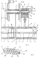
- the figures show a single end knot-tying machine, substantially formed by a central head 48 composed by a tubular duct 1 constituted by at least a couple of tiles 2, which may be radially adjusted according to the sizes of bodies 6 to be tied.
- Tiles 2 may be configurated with a circular development for cylindrical bodies 6, or with other profiles for products having different sections.
- tiles 2 may be configurated with one only couple, for a two-string longitudinal tying, or with two couples for a four-string longitudinal tying.
- the tubular duct 1 comprises a central adjustment and trueing rod 4 and a back pusher 5.
- the provolone 6 introduced into duct 1 is kept in position and pushed forwards (leftwards in the drawing) between said rod 4 and said pusher 5.
- the first fixed side pliers 7 lock end 8 of a string 9 near the side of product 6, in alignment with the longitudinal cavity 10 circumscribed by the approaching of the two opposite tiles 2.
- the second pliers 12 grip string 9 near a peripheral cavity 13 of tiles 2, in correspndence of wich cavity a spool 14 is provided on which the rest of the string is wound.
- the second pliers 12 are positioned opposite to the first pliers 7, and spool 14, provided with a potential minidivider 15, is mounted on at least a couple of pins 16, which elastically engage, by means of springs 17, in seats 18 obtained in as many circular plate wheels 19.
- the plate wheels 19 slide within fixed seats coaxially mounted relatively to the tubular duct 1.
- Seats 20 are provided with circumferential slits 21 through which pins 16 supporting spool 14 protrude.
- Seats 20 are suitably connected to the loadbearing structure of the machine, while plate wheels 19 are kept in position, with sliding rotation within said seats, by a number of pinions 23 which engage with the same through peripheral openings 24.
- pinions 23 are moved by one only movement means, constituted, for instance, by pulleys activated by one motor-belt, or other suitable device.
- spool 14 is caused to rotate around the tubular duct 1 and string 9 which unwinds from it wraps up product 6, through the peripheral cavity 13.
- equidistant tying loops 28 create which align for the whole length of product 6, which loops restrain on one side the first longitudinal tying obtained by the first side pliers 7, and create on the opposite side the second longitudinal tying constituted by the lenghts reformed step-by-step by the second pliers 12, between each loop and the following one.
- the first end 8, disengaged from the first side pliers 7, and the end engaged by the second pliers 12, are gathered and knotted 30 in correspondence of the second bottom 29.
- pins 16 on which said spool is supported are alternately retractable. For this reason, they are located within seats 18 obtained in plate wheels 19, and are provided with antagonistic springs 17 which exercise their pressure against caps 32, integral with the pins.
- cam-grooves or openings 33 coupled to external cams 34 are obtained.
- a first pin 16 for instance the one on the left side in the drawings, goes back, as its cap 32 aligns with opening 33 of its corresponding seat 20, and its spring 17 releases.
- pin 16 disengages from spool 14 the moment when string 9, pulled by pliers 20, enters throat 35 between said seat 20 and the spool. Immediately after the passage of the string, the corresponding cam 34 compresses cap 32, which is obliged to re-enter recess 18, and pin 16 protrudes again from the same seat, reassuming its starting engagement position on the spool.
- spool 14 is provided with side truncated-cone conveyors 37.
- pin 16 has a polygonal shape and engage in corresponding seats of spool 14, so as to form an engagement adequate to the restraint and the support of the same spool.
- the axle of spool 14 instead of being directly engaged with the mobile pins 16, is engaged on two intermediate side plates 37', which substitute the coaxial truncated-cone elements 37.
- a plate 37' is provided having several profiled seats wherein engage as many mobile pins 16, one for each side, relatively to the support of the axle of the same spool.
- pins 16 support and guide plates 37' on which the ends of spool 14 are engaged.
- the plate wheels stop temporary, together with the spool; the second pliers 12 go back, dragging along the part of string on which they hold grip; they raise it and cause it to pass above the same spool.
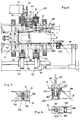
- Figs. 11 and 12 show the support system of spool 14 with several side pins, for instance three for each side, engaged in as many seats 158 obtained in the support side stirrups 37'.
- string 9 overcomes step-by-step first from one side, then from the opposite side, the various pins which go back to allow it to pass, to return then to the engagement position with stirrups 37', after each passage.
- FIGs. 6 through 11 show different alternative embodiments of the same central working head 48, of its components and its working.
- end 8 of string 9 is caused to advance along the axis of the machine by means of a mobile arm 40, whose translation is controlled by a piston 41 or a corresponding means.
- Grip 42 comprises upper pliers 43 and a friction pusher 44 with back spring 45.
- the jaws of pliers 43 form an annular space 46 wherein small pliers 47 may insert orthogonally having an alternate motion, orthogonal to the one of the mobile arm 40.
- end 8 of string 9 to align with the central head 48, substantially formed by the fixed seats and circular sectors 20, the related circular sector plate wheels 20, the related circular sector plate wheels 19, and the wrapping up spool 14 with its support and translation means.
- pliers 47 advance until they engage with the above end 8 of string 9, hook up with it and go back to their starting position, dragging along the same string which slips off from the friction grip 42, keeping its tautness.
- the jaws of the upper pliers 43 open elastically, under the traction action of the small pliers 47, being hinged on a fulcrum 155 provided with a return elastic means. In this way the string may be causes to slide easily.
- the small pliers 47 work in the aforementioned way through a guide duct 49 obtained in the front part of a front elastic pusher 50, provided with opposite openable jaws 51.
- end 8 of string 9 engages between the radial grooves 52 of said fan, the small pliers 47 let go their hold, and the string rotatingly winds on spool 14, for a prefixed and planned length, according to the type, dimensions of the tying and the advancing rate of the product to be treated and/or the number of products of a prefixed configuration to be wrapped up and tied in the production sequence.
- a friction 54 keeps the string taut, both during the wrapping up and the recoveries.
- string 9 remains longitudinally taut on a side of body 6 of grip 42 up to its aforementioned diametral frontal part, or bottom 11, and beyond, on the opposite longitudinal side, up to the alignment point substantially located in the middle of head 48, in correspondence of the circumferential cavity 13.
- the second pliers 12 grip string 3 near said peripheral cavity 13, between tiles 2, in correspondence of which cavity spool 14 on which the tying string is wound is aligned.
- pinion 59 of the spool winding motor is retracted by means of any known mechanical or electromechanical system, so as to unhook from the coupling with gear 60.
- the above condition is indispensable to allow the overtaking stage of the spool by the string.
- the engament of pinion 50 with gear 60 is realized during the winding stage of the string on spool 14 and at each end of orbital rotation of the same spool around the product to be tied, to perform the necessary recovery and mantain the right tautness of the string, after which the toothed wheels are disconnected for the above mentioned reason: the tautness of the string is mantained by means of friction 54.
- a coupling with friction wheels may be utilized instead of a coupling with tothed wheels.
- a pulley is keyed on the motor shaft 15, on which pulley a belt holds grip which has a high friction coefficient.
- the belts wraps up on a second idle lag pulley, and a third pulley with the function of idler.
- the system is caused to translate, with a mechanical or electromechanical device, until the lag pulley is aligned with the friction wheel mounted on the same spool, instead of pinion 60.
- the lag pulley and the friction wheel engage with one another by friction, through the interposition of the belt. In this way, the spool is caused to rotate.
- hooking means or hook 58 which gather the unwound part of string 9 and keeps it taut orthogonally towards the back to an extent sufficient and adequate to allow its passing above spool 14. As the string is caused to pass beyond the spool, hook 58 returns gradually, yielding the fullness of the same.
- body 6 is caused to advance at a prefixed rate and the above described operations are repeated up to the full circumferential tying.
- end restrained in the friction grip 42 is still kept in its position, while around it several sequential knotting stages are performed, proceeding in the same way as described.
- body 6 is fully knotted also in closure: end 8 detaches from fan 53, as the string has fully unwound, and the end of grip 42 is cut, releasing the finished body 6.
- the mobile arm 40 is provided with a fixed tubular body 61 in which a tubular stock 62 is placed and pushed forwards by a spring 63. Beyond body 61 two friction wheels 64 are provided, kept in touch by elastic means, such as springs.
- End 8 of string 9 is friction-engaged betweem wheels 64, while the back part is kept taut by pneumatic pliers, or the like.
- the end of the tubular stock 62 is caused to rest against a shell 65, provided with a side hole 66, alignable with the above tubular stock 62.
- a piston 67 provided in shell 65, lowers and restrains end 8 of the string, after which the same shell is retracted from such position, dragging along the string until it is aligned with the radial grooves 52 for the automatic hooking of fan 53.
- shell 65 is oriented in correspondence of cavity 13, of head 48, in alignment with said spool 14.
- string 9 After the winding on spool 14 for a prefixed length, string 9, always stretched by the back pliers, is cut by a suitably positioned blade, so that head 8 is aligned anew with the tubular stock 62.
- said head is coupleable with supporting and shifting means from tiles 2, as described, or to conveyor belts or rollers or the like for bodies 6 extended in the length, or also to flat supporting means, in which head 48 is orientable also parallelly with or without automatic product loaders.
- head 48' utilizes a circular sector fixed seat or a continuous round seat 20, with spool 14 cantilever-supported on one only side strap 37', possibly with a more extended development, which is supported by a plurality of pins 16' protruding from one of the sides of said seat 20.
- the grip of bodies 69 in grooves 68 is so regulated as to ensure the position stability of strap 37' and the related spool 14, relatively to the fixed seat 20 and the rotating plate wheel 19.
- pins 16' behave the same way as described above, retracting from seats 158' to allow the passage of the string.
- both springs 17 and cams 34 are so size as to overcome in either direction the force exercized by the pressure springs 70 on bodies 69, to disengage or engage the same from or in grooves 68.
- An accessory tool applicable to the described and illustrated tying machines, especially designed and prepared for tying products 6 with both longitudinal and circumferential turns, such as for instance, pressed pork neck, salami, provolone cheese and the like, consists of a peripheral gripping means 71, substantially formed by one or two or more couples of half-rings 72 hinged in an intermediate point of theirs 73 and having the fulcrum at one common end 74 on a retractable rod 75, with antagonistic spring 76.
- Rod 75 engages telescopically in stem 77 of a piston 78. At the end of said stem also the end parts 79 of arms 80 are connected, whose opposite ends constitute the above hinges 73 of the half-rings 72.
- the so configurated gripping means is preferably but not limitedly arranged in alignment with cavity 13 of the central head 48, with the half-rings 72 located astride the zone in which string 9 wraps up circumferentially body 6 at each knot formation.
- the pressure exercized by piston 78 causes the backwards motion of rod 75, with ensuing closing rotation of the half-rings 72 around hinges 73.
- the half-rings 72 close in this way on body 6 pressing on the same and imprisoning the longitudinal tying turns in the wished position.
- the sequential recovery of the string by spool 1 finds the longitudinal tying turns perfectly held and caused not to be in condition of sliding transversally due to the friction exercized on the same by the circumferential turn of the knot being formed, which is subject to traction.
- piston 78 causes the return of stem 77; the antagonistic spring 76 expands, pushing outwards the common fulcrum 74, and the half-rings 72 open rotating around their hinges 73.
- Body 6, freed from the grip of means 71, can in this way advance by a step, and prepare for the automatic execution of the following knot.
- the working head 48 as a whole constitutes in itself a real tying machine, independent and suitable for any type of knotting operation, independently on the type, shape, size and structure of the product to be treated.
- the versatility of the central head 48 is such as to allow wrapping ups with knottings on any type of products: from food, sausages and meats and other ones, such as pressed pork, salami, cheese submitted to step-by-step wrapping: from the most specific ones, with end knotting for hams, or with alternate constriction knotting for sausages; from those relating to any product, even of great length, such as piping sections to be covered with insulating materials or the like, peripherally tied; from those relating to clothing, where the sewing of buttons or the like require a consistent knot fixing; from any other application requiring the presence of thread-like elements, such as thread, string, rope or the like, to be engaged with knots.
Landscapes
- Engineering & Computer Science (AREA)
- Life Sciences & Earth Sciences (AREA)
- Wood Science & Technology (AREA)
- Zoology (AREA)
- Food Science & Technology (AREA)
- Mechanical Engineering (AREA)
- Basic Packing Technique (AREA)
- Braiding, Manufacturing Of Bobbin-Net Or Lace, And Manufacturing Of Nets By Knotting (AREA)
- Binders And Loading Units For Sheaves (AREA)
Claims (25)
- Machine à nouer à un seul bout constituée par une tête centrale (48) de travail comportant au moins un corps annulaire (20) subdivisé en secteurs, avec des moyens circonférentiels (19) de rotation qui s'engagent, par des broches (16') ou des couples de broches orthogonales (16), une structure de charge (37) ou (37') portant une bobine (14) pour des éléments (9) de nouage analogues à un fil ; ledit corps annulaire (20) étant accouplé à des pinces ou éléments de retenue (7), (12), (42), (47) qui, agissant sur ledit élément (9) analogue à un fil, contribuent à maintenir en adhérence longitudinale sur la périphérie de corps (6) sur lesquels les nouages doivent être réalisés et en blocage temporaire, ladite bobine (14) étant amenée à tourner autour desdits corps (6), de façon alternée avec une avance axiale pas à pas de ceux-ci, caractérisée en ce que lesdites broches (16) ou (16') sont engagées coaxialement avec des dispositifs coulissants axiaux (17), (32), (34), actionnant alternativement et séquentiellement lesdites broches ou le couple de broches et en ce que lesdites pinces ou lesdits éléments de retenue (7), (12), (42), (47) contribuent en outre à maintenir ledit élément (9) analogue à un fil en traction avec une translation radiale centrifuge et un retour qui suit, en surmontant ladite bobine.
- Machine à nouer selon la revendication 1, caractérisée en ce qu'elle comporte un conduit tubulaire (1), formé par des couples de tuiles (2) disposés de façon périphérique, dans lequel un corps (6) avance progressivement, engageant longitudinalement, à partir d'un côté, un élément de nouage ou cordon (9) dont une extrémité est engagée dans des premières pinces latérales (7) et, sur l'autre extrémité, dans la continuation du même cordon (9), qui s'engage dans les secondes pinces (12) qui le retiennent, tandis que la même cordon se déroule d'une bobine (14) pendant chaque tour, laquelle bobine est engagée pour travailler autour du conduit tubulaire et, par conséquent, du corps devant être noué, en combinaison de nouage avec des roues plates (19) situées dans des sièges annulaires (20), coaxialement au conduit tubulaire (1), lesdits couples de tuiles (2) pouvant être approches l'un de l'autre à l'exception de la présence de gorges longitudinales (10) pour le passage des tours longitudinaux du cordon (9) et d'une gorge périphérique (13) pour le passage du même cordon (9) pour son enveloppement périphérique pas à pas ; l'enveloppement en boucle pas à pas étant alternée par une élévation de l'extrémité du cordon (9), engagée dans les secondes pinces (12), qui s'ouvrent, passent en dessus, à chaque tour de la bobine, et se referment sur le côté du corps (6), toujours serrée par les secondes pinces (12) ; ledit passage étant combiné avec le dégagement et le réaccouplement des broches (16') ou des couples de broches latérales (16) avec les sièges coaxiaux correspondants obtenus sur l'axe des supports (13) de la bobine (14), alternant entre eux et conformément au passage du cordon (9), tiré par lesdites secondes pinces (12).
- Machine à nouer selon les revendications 1 et 2, caractérisée en ce que des roues plates (19) sont engagées en glissement circonférentiel dans des sièges annulaires (20) fixes coaxiaux au conduit tubulaire (1) et en ce que lesdites roues plates (19) et les sièges (20) sont formés d'au moins deux moitiés, éloignées l'une de l'autre dans la direction diamétrale d'une distance telle qu'ils forment des cavités diamétrales (22), lesquelles, à leur tour, s'alignent avec les cavités longitudinales (10) obtenues entre les couples rapprochés de tuiles (2) : lesdites roues plates ou des secteurs des roues plates étant amenés à tourner et étant maintenus en position par plusieurs pignons périphériques (23) qui les engagent à travers des ouvertures périphériques (24) obtenues sur les sièges fixes (20), qui comprennent également des fentes circonférentielles (21), desquelles font saillie, et suivent le trajet en rotation des roues plates (19), les broches ou les couples de broches latérales (16), (16') supportent la bobine (14) sur laquelle un cordon (9) est enroulé ; les broches (16) ou (16') ci-dessus sont placées dans des sièges (18) situés transversalement vers lesdites roues plates (19) et y restent au moyen de ressorts antagonistes (17) qui agissent sur leurs chapeaux (32).
- Machine à nouer selon les revendications 1, 2 et 3, caractérisée en ce que les parois arrière des sièges annulaires fixes (20) présentent des gorges ou ouvertures (33) analogues à des cames couplées à des cames extérieures (34) avec lesquelles elles s'alignent, tandis que les broches (16), (16') sont déplacées vers l'arrière par les chapeaux (32) des mêmes broches poussés par des ressorts (17) ; lesdites ouvertures et cames étant placées en correspondance des points d'arrêt de la rotation de la bobine (14) autour du conduit tubulaire, et la saillie et le rétablissement de la position des broches (16) ou (16') correspondent, alternativement, aux passages du cordon (9) au-dessus de la bobine (14) et le long d'étranglements (35) et (36), constitués entre la même boine et les sièges (20), avec croisement du cordon (9) et nouage (27) de celui-ci.
- Machine à nouer selon les revendications 1 à 4, caractérisée en ce que la bobine (14) de laquelle le cordon (9) se déroule, pendant les rotations périphériques séquentielles et alternées autour des corps (6), est pourvue d'un minidiviseur (16) qui étire le même cordon.
- Machine à nouer selon les revendications 1 à 5, caractérisée en ce que le conduit tubulaire (1) est constitué d'un ou plusieurs couples de tuiles (2) opposés de façon périphérique avec des chemins ouverts longitudinaux (10) et avec au moins une lente périphérique (13) pour le passage du cordon (9) dans les deux directions.
- Machine à nouer selon les revendications 1 à 6, caractérisée en ce que les premières pinces (7), une extrémité de retenue (8) du cordon (9) et les secondes pinces (12), qui engagent de façon alternée un point du même cordon pendant l'action d'enveloppement par rotation de celui-ci autour du corps (6) devant être noué, et l'élèvent au-dessus de la bobine (14) pendant le croisement et le nouage, sont placées dans des positions sensiblement opposées.
- Machine à nouer selon les revendications 1 à 7, caractérisée en ce que les couples de tuiles (2) sont configurés conformément à des profils de secteurs semi-circulaires ou circulaires, conformément à tout profil polygonal, et sont réglables entre eux.
- Machine à nouer selon les revendications 1 à 8, caractérisée en ce que des corps (6) devant être noués avec deux, quatre, six tours longitudinaux ou plus et avec plusieurs anneaux de nouage périphériques (28) reliés à des noeuds (27) sont guidés le long du trajet dans un sens ou dans deux sens opposés à l'intérieur du conduit tubulaire (1), au moyen d'une tige avant (4) de réglage et de redressement et d'un poussoir arrière (5), qui viennent s'appliquer sur des fonds (11) et (29) des mêmes corps.
- Machine à nouer selon les revendications 1 à 9, caractérisée en ce que des corps (6) devant être noués avec plus de deux tours longitudinaux sont soumis à des déplacements coaxiaux vers l'avant et vers l'arrière le long du conduit tubulaire (1) avec des rotations de celui-ci et des moyens retenant le cordon (9), avec des croisements de noeuds de celui-ci en correspondance avec les fonds (11) et (29).
- Machine à nouer selon les revendications 1 à 10, caractérisée en ce que la bobine (14) est supportée par deux broches coaxiales opposées (16), ayant un mouvement alterné d'éloignement et de décrochage, et d'approche et d'accrochage dans des sièges coaxiaux avec la même bobine, lesquels sont également coaxiaux avec des moyens tronconiques de guidage (37).
- Machine à nouer selon les revendications 1 à 11, caractérisée en ce que la bobine (14) tourillonne dans des plaques latérales (37') sur lesquelles au moins deux ou plus de doux sièges sont obtenus, situés sur les côtés du support de la bobine, dans lesquels s'engagent autant de broches latérales (16) faisant saillie de sièges accouplés correspondants (18) obtenus dans les roues plates.
- Machine à nouer selon les revendications 1 à 12, caractérisée en ce que les broches (16) ou (16') sont des sections polygonales et s'engagent avec des sièges correspondants complémentaires, obtenus coaxialement à la bobine (14) ou latéralement par rapport aux supports de ladite bobine, sur des plaques latérales (17') pourvues de chanfreins périphériques de guidage.
- Machine à nouer selon la revendication 1, carctérisée en ce que la tête centrale (48) de travail comporte un ou deux sièges fixes (20), avec des roues plates intérieures, circulaires et tournantes (19) dans lesquelles s'engage l'étrier unique (37') ou l'étrier double (37) supportant la bobine (14) ou le cordon (9) s'enroule sur une longueur utilisable pour nouer un ou un nombre préalablement fixé de corps (6) devant être traités; ledit ou les étriers (37'), (37) étant engagés avec la ou les roues plates précitées (19) par l'intermédiaire d'une ou deux pluralités de broches orthogonales (16'), (16), qui exécutent des mouvements alternés et séquentiels de recul et d'extension, avec dégagement et engagement ensuite avec des sièges (158') et (158) obtenus dans les mêmes étriers, conformément à, et en synchronisme avec, le croisement du cordon (9), élevé et tiré par des pinces (12) aidées par un moyen d'accrochage (58), et de la bobine précitée (14), en mouvement orbital autour du corps devant être noué (6), avec passage au-dessous du même cordon ; ladite bobine (14) étant à son tour pourvue, en, plus des moyens rotatifs de manipulation (60), (59), (15), également d'un ventilateur (53) en forme de cône sur lequel sont prévues des gorges radiales (52) dans lesquelles une extrémité (8) du cordon (9) s'engage en réalisent l'enveloppement, lorsque ledit cordon est amené à s'aligner avec le ventilateur précité au moyen de petites pinces (47) ou d'un piston (67) qui prend une extrémité (8) à partir d'un moyen d'alignement (42) ou (61), engagé avec un bras mobile (40).
- Machine à nouer selon les revendications 1 et 14, caractérisée on ce que la tête centrale (48) de travail est pourvue de deux roues ou secteurs plats circulaires (19), placés dans des sièges fixes (20) parallèles et opposés, où des pluralités de sièges orthogonaux (18) sont obtenus, lesquels logent autant de broches (16) avec des éléments élastiques (17), dont des extrémités avant font saillie des parois latérales opposées agencées côte à côte des mêmes roues plates, et s'engagent en formant support dans autant de sièges (158) obtenus sur les supports latéraux (37) de la bobine d'enroulement (14) ; lesdites broches exécutant des mouvements alternés et séquentiels de recul et d'extension en concomitance avec le cordon (9), l'une après l'autre, en alternance à partir de chacun des côtés desdits supports (37), en séquence synchronisée avec le passage de la bobine (14) sous le cordon (9), à distance du corps (6) devant être noué pendant son mouvement orbital autour du même corps.
- Machine à nouer selon les revendications 1 et 14, caractérisée en ce que la tête de travail (48') est pourvue d'une seule roue plate circulaire placée dans son propre siège fixe (20) avec lequel la roue plate est engagée, à l'intérieur de sièges orthogonaux (18) avec des moyens élastiques (17), d'une pluralité de broches (16'), qui présentent, à leurs extrémités, des gorges circonférentielles (68) pouvant être accouplées et reliées à des cavités (158') obtenues sur un étrier (37') ; lesdites cavités étant pourvues de corps ou petites sphères semi-circulaires (69) maintenus en position par des ressorts de pression (70) qui s'engagent sous pression avec des extrémités à gorges (68) desdites broches (16') ; lesdites broches exécutant des mouvements alternés et séquentiels de recul et d'extension, on synchronisme avec le passage de la bobine (14) au-dessous du cordon (9) à distance du corps (6) devant être noué, pendant son mouvement orbital autour dudit corps.
- Machine à nouer selon les revendications 1 et 14 à 16, caractérisée en ce qu'elle comporte un dispositif d'accrochage (42) ou (61), avec friction (43) ou (64), qui s'engage avec un bras mobile (40) pouvant être aligné avec la tête centrale (48), 48'), avec au moins des petites pinces (47) ou un piston (67) et avec le conduit de guidage (49) d'un poussoir avant (50) avec des mors élastiques (51) ; la tête (8) du cordon (9) s'accouplant audit dispositif d'accrochage, laquelle, dans des conditions de début de prise et de guidage, est amenée à s'aligner avec les gorges radiales (52) du ventilateur (53) en forme de cône tournant en même temps que la bobine d'enroulement (14).
- Machine à nouer selon les revendications 1 et 14 à 17, caractérisée en ce que le dispositif d'accrochage (42) relié au bras mobile (40) comporte une prise à friction avec des mors supérieurs et des pinces (43) pourvus d'un espace annulaire (46) dans lequel de petites pinces (47) peuvent être introduites pour prendre ladite extrémité (8) ; lesdites pinces (43) pouvant être ouvertes sous la traction du cordon, au moyen d'un mouvement autour d'un point d'appui (155) avec un retour élastique (156).
- Machine à nouer selon les revendications 1 et 14 à 17, caractérisée en ce que le dispositif d'accrochage (61) comporte la liaison télescopique élastique de deux corps tubulaires coaxiaux (61) et (62), le premier étant logé dans l'autre avec interposition d'un ressort (63) ; lesdits corps tubulaires pouvant être alignés avec un trou (66) d'un autre corps tubulaire orthogonal (65) dans lequel un piston retenant l'extrémité (8) du cordon (9) est prévu.
- Machine à nouer selon les revendications 1 et 14 à 19, caractérisée en ce qu'elle comporte un poussoir élastique avant, avec des mors mobiles (51) pouvant être ouverts par pression, entre lesquels un conduit de guidage et un secteur d'alignement (55) pour le cordon de nouage (9) sont formés.
- Machine à nouer selon les revendications 1 et 14 à 20, caractérisée en ce que les broches (16) et (16') sont commandées, dans leurs mouvements de recul et de retour relativement aux cavités (158) et (158'), au moyen de cames arrière fixes (33) situées sur les côtés desdits secteurs fixes (20) ; lesdites cames pouvant être remplacées par des pistons pneumatiques ou hydrauliques, par des systèmes électromécaniques avec des électro-aimants ou analogues.
- Machine à nouer selon les revendications 1 et 14 à 21, caractérisée en ce que la commande à moteur (15) d'une roue dentée (60) accouplée à la bobine mobile (14) comporte un pignon (59) appliqué a un moyen rétractable mécanique ou électromécanique qui décroche l'accouplement pendant les étapes de croisement de la bobine (14) par le cordon tendu (9), passant au-dessous d'elle, et raccroche l'accouplement pendant l'étape d'enroulement du cordon sur la même bobine, et à chaque fin d'une rotation orbitale de la bobine autour du corps (6) devant être noué, avec la fonction d'étirer le cordon.
- Machine à nouer selon les revendications 1 à 8, caractérisée en ce que la commande à moteur (15) est pourvue d'une poulie sur laquelle s'engage une courroie à coefficient de frottement élevé, qui s'accouple avec une deuxième poulie de retenue et une troisième poulie d'étirement ; ladite poulie de retenue s'engageant en adhérence et en retenue avec, ou se dégageant de, une roue de friction calée sur la bobine (14), ledit engagement dépendant de l'enroulement du cordon (9) sur la bobine et de la tension du même cordon à la fin de chaque rotation orbitale de la bobine autour du corps (6) devant être noué.
- Machine à nouer selon les revendications 1 et 14 à 23, caractérisée en ce que le cordon enroulé sur une bobine (14) est étiré au moyen d'une friction (54).
- Machine à nouer selon les revendications 1 et 14 à 24, caractérisée en ce qu'elle peut être pourvue ou non d'au moins un moyen de prise périphérique, tel que des demianneaux (72) articulés en un point intermédiaire d'eux-mêmes et ayant leur point d'appui à une extrémité commune (74) sur une tige rétractable (75) avec un ressort de rappel (76), qui S'engage télescopiquement avec un piston d'actionnement (78) dont une extrémité extérieure engage aussi les parties extrêmes (79) de bras (80) constituant le moyen sur lequel des artioulations (73) sont placées ; ledit moyen de prise (71) étant aligné avec une cavité (13) des têtes centrales (48), (48'), les demi-anneaux étant placés de façon à engendrer la zone où le cordon (9) est enroulé autour des corps (6) pour la formation dos noeuds, et avec les demianneaux qui réalisent une prise autour des corps (6) pendant les étapes de récupération et d'étirement du cordon noué.
Applications Claiming Priority (4)
| Application Number | Priority Date | Filing Date | Title |
|---|---|---|---|
| ITRE940101 IT1268857B1 (it) | 1994-12-01 | 1994-12-01 | Macchina legatrice a nodo ad unico capo |
| ITRE940101 | 1994-12-01 | ||
| ITRE950039 IT1280086B1 (it) | 1995-07-13 | 1995-07-13 | Perfezionamenti a macchine legatrici a nodo ad unico capo |
| ITRE950039 | 1995-07-13 |
Publications (3)
| Publication Number | Publication Date |
|---|---|
| EP0716018A2 EP0716018A2 (fr) | 1996-06-12 |
| EP0716018A3 EP0716018A3 (fr) | 1996-09-04 |
| EP0716018B1 true EP0716018B1 (fr) | 1999-02-10 |
Family
ID=26331972
Family Applications (1)
| Application Number | Title | Priority Date | Filing Date |
|---|---|---|---|
| EP95118360A Expired - Lifetime EP0716018B1 (fr) | 1994-12-01 | 1995-11-22 | Machine de nouage à bout unique |
Country Status (3)
| Country | Link |
|---|---|
| EP (1) | EP0716018B1 (fr) |
| AT (1) | ATE176642T1 (fr) |
| DE (1) | DE69507780D1 (fr) |
Families Citing this family (3)
| Publication number | Priority date | Publication date | Assignee | Title |
|---|---|---|---|---|
| ITPR20110040A1 (it) * | 2011-05-17 | 2012-11-18 | Fipal S R L | Macchina legatrice per prodotti sostanzialmente oblunghi da avvolgere e annodare. |
| EP3491928B1 (fr) * | 2017-11-29 | 2020-05-20 | INOX Meccanica S.R.L. | Machine de fixation de produits alimentaires |
| ES2808100T3 (es) * | 2018-03-29 | 2021-02-25 | Inotec Gmbh Maschinenentwicklung Und Vertrieb | Dispositivo y procedimiento para el atado de una masa introducida en una piel |
Family Cites Families (4)
| Publication number | Priority date | Publication date | Assignee | Title |
|---|---|---|---|---|
| US2328085A (en) * | 1941-12-12 | 1943-08-31 | Maccarini Carlo | Application of cords to food products |
| DE3219163A1 (de) * | 1982-05-21 | 1983-11-24 | Willi 6935 Waldbrunn Benz | Ueberlastsicherung fuer eine schnuermaschine |
| IT1159209B (it) * | 1982-07-21 | 1987-02-25 | Claudio Ronchei | Perfezionamenti a macchine imbrigliatrici per prodotti alimentari,quali carni,formaggi e simili |
| DE8906233U1 (de) * | 1989-05-20 | 1989-08-17 | Maschinenfabrik Gerd Mosca Gmbh, 6931 Zwingenberg | Maschine zum Umschnüren von Packgut |
-
1995
- 1995-11-22 DE DE69507780T patent/DE69507780D1/de not_active Expired - Lifetime
- 1995-11-22 EP EP95118360A patent/EP0716018B1/fr not_active Expired - Lifetime
- 1995-11-22 AT AT95118360T patent/ATE176642T1/de not_active IP Right Cessation
Also Published As
| Publication number | Publication date |
|---|---|
| ATE176642T1 (de) | 1999-02-15 |
| EP0716018A3 (fr) | 1996-09-04 |
| EP0716018A2 (fr) | 1996-06-12 |
| DE69507780D1 (de) | 1999-03-25 |
Similar Documents
| Publication | Publication Date | Title |
|---|---|---|
| KR101295409B1 (ko) | 해초류 포자 끈 결속장치 | |
| US4570415A (en) | Vegetable banding apparatus | |
| EP0120948A1 (fr) | Machine et procede de nouage. | |
| JPS61236346A (ja) | 固定子コイルレーシングコードの固定装置及び固定方法 | |
| EP0716018A2 (fr) | Machine de nouage à bout unique | |
| US20150298837A1 (en) | High-precision machine for binding bales and binding method | |
| CN107313174A (zh) | 一种打结方法 | |
| CA1095554A (fr) | Traduction non-disponible | |
| US6601880B2 (en) | Method and apparatus for making a knot with flexible material wrapped around an article | |
| JPS5917609B2 (ja) | 端コイルを紐でくゝる方法及び装置 | |
| JP6029194B2 (ja) | 紐結束 | |
| US2944752A (en) | Machine for packing pile fabrics | |
| US1196466A (en) | Machine for crimping and tying sacks. | |
| US3670783A (en) | Cable tying machine | |
| CN119975986A (zh) | 一种适用于大尺寸柔性袋的自动绕绳打结机及打结方法 | |
| CA2383430C (fr) | Methode et dispositif permettant de faire un noeud autour d'un article a l'aide de materiau flexible | |
| DE926295C (de) | Maschine zum Abbinden von Wursthautenden u. dgl. | |
| JP2644394B2 (ja) | 汎用結束機 | |
| ITRE940101A1 (it) | Macchina legatrice a nodo ad unico capo | |
| JP2026511665A (ja) | リボンで編み込まれたチェーンを製造する機械 | |
| KR100437128B1 (ko) | 주낙용 아릿줄 제작기 및 제작방법 | |
| RU2588544C2 (ru) | Узловязальное устройство и картриджная система для подачи к этому устройству обвязывающей нити | |
| JPH01279014A (ja) | 結束方法および装置 | |
| ITRE950039A1 (it) | Perfezionamenti a macchine legatrici a nodo ad unico capo | |
| WO2002087972A1 (fr) | Procede et appareil permettant de faire un noeud au moyen d'une matiere souple enroulee autour d'un article |
Legal Events
| Date | Code | Title | Description |
|---|---|---|---|
| PUAI | Public reference made under article 153(3) epc to a published international application that has entered the european phase |
Free format text: ORIGINAL CODE: 0009012 |
|
| AK | Designated contracting states |
Kind code of ref document: A2 Designated state(s): AT BE CH DE DK ES FR GB GR IE LI LU NL PT SE |
|
| PUAL | Search report despatched |
Free format text: ORIGINAL CODE: 0009013 |
|
| AK | Designated contracting states |
Kind code of ref document: A3 Designated state(s): AT BE CH DE DK ES FR GB GR IE LI LU NL PT SE |
|
| 17P | Request for examination filed |
Effective date: 19970127 |
|
| GRAG | Despatch of communication of intention to grant |
Free format text: ORIGINAL CODE: EPIDOS AGRA |
|
| 17Q | First examination report despatched |
Effective date: 19980513 |
|
| GRAG | Despatch of communication of intention to grant |
Free format text: ORIGINAL CODE: EPIDOS AGRA |
|
| GRAH | Despatch of communication of intention to grant a patent |
Free format text: ORIGINAL CODE: EPIDOS IGRA |
|
| GRAH | Despatch of communication of intention to grant a patent |
Free format text: ORIGINAL CODE: EPIDOS IGRA |
|
| GRAH | Despatch of communication of intention to grant a patent |
Free format text: ORIGINAL CODE: EPIDOS IGRA |
|
| GRAA | (expected) grant |
Free format text: ORIGINAL CODE: 0009210 |
|
| AK | Designated contracting states |
Kind code of ref document: B1 Designated state(s): AT BE CH DE DK ES FR GB GR IE LI LU NL PT SE |
|
| PG25 | Lapsed in a contracting state [announced via postgrant information from national office to epo] |
Ref country code: SE Free format text: THE PATENT HAS BEEN ANNULLED BY A DECISION OF A NATIONAL AUTHORITY Effective date: 19990210 Ref country code: NL Free format text: LAPSE BECAUSE OF FAILURE TO SUBMIT A TRANSLATION OF THE DESCRIPTION OR TO PAY THE FEE WITHIN THE PRESCRIBED TIME-LIMIT Effective date: 19990210 Ref country code: LI Free format text: LAPSE BECAUSE OF FAILURE TO SUBMIT A TRANSLATION OF THE DESCRIPTION OR TO PAY THE FEE WITHIN THE PRESCRIBED TIME-LIMIT Effective date: 19990210 Ref country code: GR Free format text: LAPSE BECAUSE OF NON-PAYMENT OF DUE FEES Effective date: 19990210 Ref country code: ES Free format text: THE PATENT HAS BEEN ANNULLED BY A DECISION OF A NATIONAL AUTHORITY Effective date: 19990210 Ref country code: CH Free format text: LAPSE BECAUSE OF FAILURE TO SUBMIT A TRANSLATION OF THE DESCRIPTION OR TO PAY THE FEE WITHIN THE PRESCRIBED TIME-LIMIT Effective date: 19990210 Ref country code: BE Free format text: LAPSE BECAUSE OF FAILURE TO SUBMIT A TRANSLATION OF THE DESCRIPTION OR TO PAY THE FEE WITHIN THE PRESCRIBED TIME-LIMIT Effective date: 19990210 Ref country code: AT Free format text: LAPSE BECAUSE OF FAILURE TO SUBMIT A TRANSLATION OF THE DESCRIPTION OR TO PAY THE FEE WITHIN THE PRESCRIBED TIME-LIMIT Effective date: 19990210 |
|
| REF | Corresponds to: |
Ref document number: 176642 Country of ref document: AT Date of ref document: 19990215 Kind code of ref document: T |
|
| REG | Reference to a national code |
Ref country code: CH Ref legal event code: EP |
|
| REG | Reference to a national code |
Ref country code: IE Ref legal event code: FG4D |
|
| ET | Fr: translation filed | ||
| REF | Corresponds to: |
Ref document number: 69507780 Country of ref document: DE Date of ref document: 19990325 |
|
| PG25 | Lapsed in a contracting state [announced via postgrant information from national office to epo] |
Ref country code: PT Free format text: LAPSE BECAUSE OF FAILURE TO SUBMIT A TRANSLATION OF THE DESCRIPTION OR TO PAY THE FEE WITHIN THE PRESCRIBED TIME-LIMIT Effective date: 19990510 Ref country code: DK Free format text: LAPSE BECAUSE OF FAILURE TO SUBMIT A TRANSLATION OF THE DESCRIPTION OR TO PAY THE FEE WITHIN THE PRESCRIBED TIME-LIMIT Effective date: 19990510 |
|
| PG25 | Lapsed in a contracting state [announced via postgrant information from national office to epo] |
Ref country code: DE Free format text: LAPSE BECAUSE OF FAILURE TO SUBMIT A TRANSLATION OF THE DESCRIPTION OR TO PAY THE FEE WITHIN THE PRESCRIBED TIME-LIMIT Effective date: 19990511 |
|
| NLV1 | Nl: lapsed or annulled due to failure to fulfill the requirements of art. 29p and 29m of the patents act | ||
| REG | Reference to a national code |
Ref country code: CH Ref legal event code: PL |
|
| PGFP | Annual fee paid to national office [announced via postgrant information from national office to epo] |
Ref country code: FR Payment date: 19991019 Year of fee payment: 5 |
|
| PG25 | Lapsed in a contracting state [announced via postgrant information from national office to epo] |
Ref country code: LU Free format text: LAPSE BECAUSE OF NON-PAYMENT OF DUE FEES Effective date: 19991122 Ref country code: IE Free format text: LAPSE BECAUSE OF NON-PAYMENT OF DUE FEES Effective date: 19991122 Ref country code: GB Free format text: LAPSE BECAUSE OF NON-PAYMENT OF DUE FEES Effective date: 19991122 |
|
| PLBE | No opposition filed within time limit |
Free format text: ORIGINAL CODE: 0009261 |
|
| STAA | Information on the status of an ep patent application or granted ep patent |
Free format text: STATUS: NO OPPOSITION FILED WITHIN TIME LIMIT |
|
| 26N | No opposition filed | ||
| GBPC | Gb: european patent ceased through non-payment of renewal fee |
Effective date: 19991122 |
|
| REG | Reference to a national code |
Ref country code: IE Ref legal event code: MM4A |
|
| PG25 | Lapsed in a contracting state [announced via postgrant information from national office to epo] |
Ref country code: FR Free format text: LAPSE BECAUSE OF NON-PAYMENT OF DUE FEES Effective date: 20010731 |
|
| REG | Reference to a national code |
Ref country code: FR Ref legal event code: ST |