EP0716043B1 - Dispositif de traire automatique d'animaux, par exemple des vaches, pourvu d'un récipient pressurisable - Google Patents
Dispositif de traire automatique d'animaux, par exemple des vaches, pourvu d'un récipient pressurisable Download PDFInfo
- Publication number
- EP0716043B1 EP0716043B1 EP19950203327 EP95203327A EP0716043B1 EP 0716043 B1 EP0716043 B1 EP 0716043B1 EP 19950203327 EP19950203327 EP 19950203327 EP 95203327 A EP95203327 A EP 95203327A EP 0716043 B1 EP0716043 B1 EP 0716043B1
- Authority
- EP
- European Patent Office
- Prior art keywords
- implement
- pressure vessel
- milking
- valve
- robot
- Prior art date
- Legal status (The legal status is an assumption and is not a legal conclusion. Google has not performed a legal analysis and makes no representation as to the accuracy of the status listed.)
- Expired - Lifetime
Links
- 241001465754 Metazoa Species 0.000 title claims description 28
- 241000283690 Bos taurus Species 0.000 title claims 2
- 239000012530 fluid Substances 0.000 claims description 35
- 210000002445 nipple Anatomy 0.000 claims description 29
- 239000007788 liquid Substances 0.000 claims description 15
- 239000007921 spray Substances 0.000 claims description 13
- 238000009434 installation Methods 0.000 claims description 11
- 230000007423 decrease Effects 0.000 claims description 3
- 230000001419 dependent effect Effects 0.000 claims 2
- 238000010276 construction Methods 0.000 description 9
- 210000000481 breast Anatomy 0.000 description 6
- 239000008267 milk Substances 0.000 description 5
- 210000004080 milk Anatomy 0.000 description 5
- 235000013336 milk Nutrition 0.000 description 5
- 238000005507 spraying Methods 0.000 description 5
- 230000000249 desinfective effect Effects 0.000 description 3
- 238000000034 method Methods 0.000 description 2
- 239000002245 particle Substances 0.000 description 2
- 210000001015 abdomen Anatomy 0.000 description 1
- 230000003213 activating effect Effects 0.000 description 1
- 239000000969 carrier Substances 0.000 description 1
- 238000011109 contamination Methods 0.000 description 1
- 230000003247 decreasing effect Effects 0.000 description 1
- 238000007599 discharging Methods 0.000 description 1
- 230000000694 effects Effects 0.000 description 1
- 239000002184 metal Substances 0.000 description 1
- 239000002689 soil Substances 0.000 description 1
- 230000000007 visual effect Effects 0.000 description 1
Images


Classifications
-
- A—HUMAN NECESSITIES
- A01—AGRICULTURE; FORESTRY; ANIMAL HUSBANDRY; HUNTING; TRAPPING; FISHING
- A01J—MANUFACTURE OF DAIRY PRODUCTS
- A01J5/00—Milking machines or devices
- A01J5/013—On-site detection of mastitis in milk
- A01J5/0138—On-site detection of mastitis in milk by using temperature
-
- A—HUMAN NECESSITIES
- A01—AGRICULTURE; FORESTRY; ANIMAL HUSBANDRY; HUNTING; TRAPPING; FISHING
- A01J—MANUFACTURE OF DAIRY PRODUCTS
- A01J5/00—Milking machines or devices
- A01J5/013—On-site detection of mastitis in milk
- A01J5/0134—On-site detection of mastitis in milk by using filters or decanters
-
- A—HUMAN NECESSITIES
- A01—AGRICULTURE; FORESTRY; ANIMAL HUSBANDRY; HUNTING; TRAPPING; FISHING
- A01J—MANUFACTURE OF DAIRY PRODUCTS
- A01J5/00—Milking machines or devices
- A01J5/017—Automatic attaching or detaching of clusters
- A01J5/0175—Attaching of clusters
-
- A—HUMAN NECESSITIES
- A01—AGRICULTURE; FORESTRY; ANIMAL HUSBANDRY; HUNTING; TRAPPING; FISHING
- A01J—MANUFACTURE OF DAIRY PRODUCTS
- A01J7/00—Accessories for milking machines or devices
- A01J7/04—Accessories for milking machines or devices for treatment of udders or teats, e.g. for cleaning
Definitions
- the invention relates to an implement for milking animals in which is arranged a pressure vessel according to the preamble of claim 1.
- an implement for milking animals of the sort as defined above comprising the characterizing features of claim 1.
- the valve associated with the filling opening this opening is closed off automatically at the moment when the pressure vessel is pressurized from the pressurized air or gas line. Conversely when the pressure in the pressure vessel is removed the valve is automatically released.
- the filling opening is enabled, whereafter the operating person can pour fluid into the pressure vessel; then, the filling opening is closed off automatically at the moment that the pressure vessel is pressurized again when connected to the pressurized air or gas line by means of the further valve.
- the valve is designed as a non-return valve.
- the non-return valve is designed as a rubber disc, which is suspended pivotable from one point and, in its closed-off position, is supported against a rubber ring disposed around the filling opening of the pressure vessel, at the inside thereof.
- the pressurized air or gas line is connected to the already present pneumatic system of a milking robot.
- the pressure vessel is provided on the robot arm construction of the milking robot and in particular the robot arm construction is movable in the longitudinal direction of the milking parlour.
- a roller 20 By this motor 19 there is driven a roller 20, preferably having a rubber surface, which roller is pushed against the upper frame part 4 by means of a spring member 21.
- the spring member 21 being active between the motor 19 and the carrier frame 9, the roller 20 to be driven by the motor 19 is kept pushed against the upper frame part 4, so that, when the motor is driven, it will be moved along the upper frame part 4 and, consequently, the entire carrier frame 9 will be moved.
- a sensor 22 comprising e.g. a laser.
- the upper arm 34 of this quadrangle construction 33 has a fixed length, while the lower arm 35 thereof is adjustable in length so as to enable the robot arm installation 31 to be adjusted to a limited extent.
- the robot arm installation 31 comprises a substantially vertical robot arm 36 as well as robot arms 37 that are movable in a substantially horizontal plane.
- the robot arm 36 is connected with the beam 11 of the carrier frame 9.
- the control cylinder 32 is active between the carrier frame 9 and the robot arm 36.
- the orientation of the robot arm 36 is slightly adjustable, the spatial position of the action point of the control cylinder 32 at the robot arm 36 is not entirely fixed.
- a position feedback rod 43 by means of which, in a part 43A of the control cylinder, a potentiometer will deduce a signal indicating the position of the piston rod relative to the cylinder housing, while, with the aid of the signal supplied by the potentiometer, the position of the piston rod 41 relative to the cylinder housing can be post-guided to a preset position.
- the control cylinder 32 is provided with an overload protection enabling the robot arm installation 31 to be moved into its lowest position, as soon as the animal present in the milking parlour exercises a pressure thereon, e.g. by kicking.
- the arm 46 is pivotal relative to the arm 45 about a substantially vertical pivot shaft 51 and is pivoted with respect thereto by means of a control cylinder 52 disposed between the arm 46 and that end of the arm 45 that is situated near the connecting piece 49.
- a control cylinder 52 disposed between the arm 46 and that end of the arm 45 that is situated near the connecting piece 49.
- the teat cups 53 and 54 Near the end of the arm 46 there are provided the teat cups 53 and 54 to be connected to the teats of a cow.
- a slide which is movable along the arm 46 and on which there is present a sensor 55, which by a sectorwise scanning movement can accurately determine the position of the teats, so that the control cylinders 32, 47 and 52 can be computer-controlled in such a way that the teat cups will be connected properly to the teats.
- the connection between the teat cups and the milk tank will be interrupted and there will be realized a connection with e.g. the rinsing fluid reservoir.
- fluid can be circulated via the supply lines 59 and the spray nozzles, while subsequently, through the teat cups and the milk lines connected thereto, the rinsing fluid will be conveyed to the reservoir.
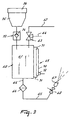
- a discharge line 65 for discharging fluid stored under pressure in said pressure vessel.
- a filter 66 by means of which particles that may be present in the fluid can be filtered out.
- a spray nozzle 67 along which, according to a fixed pattern, the pressurized fluid is atomized.
- a computer-controlled cock 68 In the discharge line 65, near the spray nozzle 67, there is furthermore incorporated a computer-controlled cock 68.
- the pressure vessel 61 is provided with a liquid level meter 69, which, in the preferred embodiment, is designed as a transparent tube 70 disposed at the outside of the pressure vessel 61 and extending substantially along the height of the pressure vessel 61, while, at its lower and upper ends, via lines 71, it is connected with the fluid present in the pressure vessel 61. Additionally, near the lower side of the transparent tube 70 there is provided a liquid level sensor 72 supplying a signal to a (non-shown) computer when the fluid level in the pressure vessel 61 decreases below a fixed, adjustable minimum value.
- the pressure vessel 61 is attached to the vertical robot arm 36 of the robot arm installation 31, and the spray nozzle 67 is disposed between the two foremost teat cups 53 on the end of the robot arm 45 so as to produce, relative to the latter robot arm, a forwardly and upwardly directed fan-shaped atomizing pattern.
- the liquid level sensor 69 supplies a signal to the computer and the attention of the operating person is drawn to the fact that the pressure vessel 61 has to be replenished.
- the further valve 63 via the pressure relief line 64 the pressure in the pressure vessel 61 is removed and, as a result, the non-return valve 74 is automatically deactivated.
- an operating person can pour fluid into the filling funnel 75, whereafter, under the weight of the fluid, the non-return valve 74 opens and the fluid flows into the pressure vessel 61. Via the transparent tube 71, the operating person can accurately determine to what extent the liquid level in the pressure vessel 61 has raised.
- the teat cups 53 are removed from the teats and are withdrawn to the robot arm 45.
- the robot arm 45 is positioned in such a way that the fan-shaped spraying pattern of the spray nozzle 67 just touches the back side of the udder of the milked animal.
- the positioning of the robot arm 45 can be effected by means of the sensor 56 and/or by means of animal-depending coordinates previously inputted into a control computer of the robot arm 45.
- the valve 68 is opened, while at the same time the robot arm is moved in a horizontal plane in the direction of the front side of the animal.
Landscapes
- Life Sciences & Earth Sciences (AREA)
- Animal Husbandry (AREA)
- Environmental Sciences (AREA)
- Manipulator (AREA)
- External Artificial Organs (AREA)
- Cleaning In General (AREA)
Claims (16)
- Instrument pour la traite d'animaux, tels que des vaches, ledit instrument comprenant un récipient sous pression (61) agencé pour stocker un fluide sous pression d'air ou de gaz, lequel agencement de récipient sous pression a :caractérisé en ce que ledit autre clapet (63) est adapté afin de fonctionner dans l'un quelconque des modes suivants :une conduite (62) pour air ou gaz sous pression opérationnelle pour mettre le fluide dans le récipient sous pression (61) à une pression souhaitée ;une conduite de refoulement (65) pour le fluide, dans laquelle conduite de refoulement (65) il est inclus un robinet (68) ; etune ouverture de remplissage pouvant être fermée ayant un clapet (73) ;un autre clapet (63) étant incorporé dans la conduite d'air ou de gaz sous pression (62) ;moyennant quoi le clapet (73) est adapté pour répondre en prenant automatiquement sa position fermée, à chaque fois que la pression d'air ou de gaz prévalente dans le récipient sous pression (61) est supérieure à la pression ambiante, fermant ainsi l'ouverture de remplissage dudit récipient sous pression (61).a) permettre à l'air ou au gaz sous pression provenant de ladite conduite sous pression (62) d'entrer dans le récipient sous pression (61) ; oub) permettre à l'air ou au gaz présent sous pression dans ledit récipient sous pression (61) de sortir de l'instrument ; ouc) interrompre les opérations a) et/ou b) de l'autre clapet (63) ;
- Instrument selon la revendication 1, caractérisé en ce que l'instrument comprend au moins un robot de traite (8) pour relier automatiquement les gobelets trayeurs (54) aux trayons d'un animal et au moins une machine de traite pour la traite automatique de l'animal.
- Instrument selon la revendication 1 ou 2, caractérisé en ce que l'autre clapet (63) est disposé au niveau de ou près du côté supérieur du récipient sous pression (61).
- Instrument selon la revendication 1, 2 ou 3, caractérisé en ce que le clapet (73) opérationnel sous air ou gaz sous pression est un clapet anti-retour.
- Instrument selon la revendication 4, caractérisé en ce que le clapet anti-retour (74) comprend un disque de caoutchouc.
- Instrument selon l'une quelconque des revendications précédentes, caractérisé en ce qu'au-dessus du clapet (73) il est disposé un entonnoir de remplissage (75) qui, au niveau de son côté supérieur, est pourvu d'un couvercle (76).
- Instrument selon l'une quelconque des revendications précédentes, caractérisé en ce que dans la conduite de refoulement (65) il est incorporé un élément filtrant (66).
- Instrument selon l'une quelconque des revendications 3 à 6, caractérisé en ce que le clapet (73) est disposé au niveau de ou près du côté supérieur du récipient sous pression (61).
- Instrument selon l'une quelconque des revendications précédentes, caractérisé en ce que le récipient sous pression (61) est pourvu d'un dispositif de mesure de niveau de liquide (69).
- Instrument selon la revendication 9, caractérisé en ce que le dispositif de mesure de niveau de liquide (69) est conçu en tant que tube transparent (70) disposé à l'extérieur du récipient sous pression (61) et s'étendant sensiblement le long de la hauteur de celui-ci, lequel tube (70), au niveau de ses extrémités supérieure et inférieure, est raccordé au récipient sous pression (61).
- Instrument selon la revendication 9 ou 10, caractérisé en ce que le dispositif de mesure de niveau de liquide (69) est pourvu d'un capteur de niveau de liquide (72) fournissant un signal lorsque le niveau du fluide dans le récipient sous pression (61) diminue en dessous d'une valeur minimum ajustable fixe.
- Instrument selon la revendication 2 ou selon l'une quelconque des revendications 3 à 11 lorsqu'elle dépend de la revendication 2, caractérisé en ce que la conduite d'air ou de gaz sous pression (62) est raccordée au système pneumatique du robot de traite (8).
- Instrument selon la revendication 2 ou selon l'une quelconque des revendications 3 à 12 lorsqu'elle dépend de la revendication 2, caractérisé en ce que le robot de traite a une installation de bras robotisé (31), et en ce que le récipient sous pression (61) est prévu sur l'installation de bras robotisé (31) du robot de traite.
- Instrument selon la revendication 13, caractérisé en ce que l'installation de bras robotisé (31) est mobile dans la direction longitudinale d'une salle de traite (1).
- Instrument selon l'une quelconque des revendications précédentes, caractérisé en ce que le robinet (68) est un robinet commandé par ordinateur.
- Instrument selon l'une quelconque des revendications précédentes, caractérisé en ce qu'à l'extrémité de la conduite de refoulement (65) il est raccordé une buse de pulvérisation (67).
Applications Claiming Priority (2)
| Application Number | Priority Date | Filing Date | Title |
|---|---|---|---|
| NL9402077 | 1994-12-09 | ||
| NL9402077A NL9402077A (nl) | 1994-12-09 | 1994-12-09 | Inrichting voor het automatisch melken van dieren, zoals koeien. |
Publications (2)
| Publication Number | Publication Date |
|---|---|
| EP0716043A1 EP0716043A1 (fr) | 1996-06-12 |
| EP0716043B1 true EP0716043B1 (fr) | 2005-07-27 |
Family
ID=19864991
Family Applications (1)
| Application Number | Title | Priority Date | Filing Date |
|---|---|---|---|
| EP19950203327 Expired - Lifetime EP0716043B1 (fr) | 1994-12-09 | 1995-12-08 | Dispositif de traire automatique d'animaux, par exemple des vaches, pourvu d'un récipient pressurisable |
Country Status (3)
| Country | Link |
|---|---|
| EP (1) | EP0716043B1 (fr) |
| DE (1) | DE69534335T2 (fr) |
| NL (1) | NL9402077A (fr) |
Families Citing this family (1)
| Publication number | Priority date | Publication date | Assignee | Title |
|---|---|---|---|---|
| US6446578B1 (en) | 1997-09-24 | 2002-09-10 | Maxim Products Limited | Spraying methods and apparatus |
Family Cites Families (3)
| Publication number | Priority date | Publication date | Assignee | Title |
|---|---|---|---|---|
| US2520175A (en) * | 1944-12-14 | 1950-08-29 | American Can Co | Liquid dispensing machine with means for controlling the pressure at point of discharge |
| US4403569A (en) * | 1981-12-29 | 1983-09-13 | Bennett Arthur J R | Milking machine |
| DE9016677U1 (de) * | 1990-11-09 | 1991-08-22 | Pannenborg, Jens, 5204 Lohmar | Vorrichtung zum Be- und Nachfüllen von Flüssigkeiten in Wassersystemen |
-
1994
- 1994-12-09 NL NL9402077A patent/NL9402077A/nl not_active Application Discontinuation
-
1995
- 1995-12-08 DE DE1995634335 patent/DE69534335T2/de not_active Expired - Fee Related
- 1995-12-08 EP EP19950203327 patent/EP0716043B1/fr not_active Expired - Lifetime
Also Published As
| Publication number | Publication date |
|---|---|
| DE69534335T2 (de) | 2006-05-24 |
| EP0716043A1 (fr) | 1996-06-12 |
| DE69534335D1 (de) | 2005-09-01 |
| NL9402077A (nl) | 1996-07-01 |
Similar Documents
| Publication | Publication Date | Title |
|---|---|---|
| EP0536836B2 (fr) | Procédé pour nettoyer les manchons trayeur et dispositif de traite d'animaux en applicant ledit procédé | |
| CA2336838C (fr) | Procede et dispositif pour nettoyer le pis ou mamelle d'une vache | |
| EP0789995B1 (fr) | Dispositif de traite automatique d'animaux | |
| EP0188303B1 (fr) | Dispositif et procédé de traite d'animaux, par exemple des vaches | |
| EP0332235B1 (fr) | Dispositif de traite automatique d'animaux | |
| WO1996011568A2 (fr) | Procede et outil pour la traite automatique d'un animal tel qu'une vache | |
| EP1234496B1 (fr) | Procédé pour nettoyer les manchons trayeurs et dispositif pour la traite d'animaux | |
| EP0800763B1 (fr) | Dispositif de traite d'animaux | |
| EP0728411B1 (fr) | Dispositif de traite d'animaux | |
| EP0716043B1 (fr) | Dispositif de traire automatique d'animaux, par exemple des vaches, pourvu d'un récipient pressurisable | |
| EP0717926B1 (fr) | Dispositif de traire automatique d'animaux, par exemple des vaches | |
| EP1214877B1 (fr) | Méthode de traite d'animaux | |
| EP0647392B2 (fr) | Dispositif de traite automatique d'animaux | |
| JP3416665B6 (ja) | 搾乳動物の乳首の後処理方法及び該方法を行うための搾乳動物用器具 | |
| JPH07274755A (ja) | 搾乳機 |
Legal Events
| Date | Code | Title | Description |
|---|---|---|---|
| PUAI | Public reference made under article 153(3) epc to a published international application that has entered the european phase |
Free format text: ORIGINAL CODE: 0009012 |
|
| AK | Designated contracting states |
Kind code of ref document: A1 Designated state(s): DE FR GB NL SE |
|
| 17P | Request for examination filed |
Effective date: 19961202 |
|
| 17Q | First examination report despatched |
Effective date: 19980421 |
|
| RAP1 | Party data changed (applicant data changed or rights of an application transferred) |
Owner name: MAASLAND N.V. |
|
| GRAP | Despatch of communication of intention to grant a patent |
Free format text: ORIGINAL CODE: EPIDOSNIGR1 |
|
| RTI1 | Title (correction) |
Free format text: AN IMPLEMENT FOR AUTOMATICALLY MILKING ANIMALS, SUCH AS COWS,COMPRISING A PRESSURE VESSEL |
|
| GRAS | Grant fee paid |
Free format text: ORIGINAL CODE: EPIDOSNIGR3 |
|
| GRAA | (expected) grant |
Free format text: ORIGINAL CODE: 0009210 |
|
| AK | Designated contracting states |
Kind code of ref document: B1 Designated state(s): DE FR GB NL SE |
|
| REG | Reference to a national code |
Ref country code: GB Ref legal event code: FG4D |
|
| REF | Corresponds to: |
Ref document number: 69534335 Country of ref document: DE Date of ref document: 20050901 Kind code of ref document: P |
|
| PG25 | Lapsed in a contracting state [announced via postgrant information from national office to epo] |
Ref country code: SE Free format text: LAPSE BECAUSE OF FAILURE TO SUBMIT A TRANSLATION OF THE DESCRIPTION OR TO PAY THE FEE WITHIN THE PRESCRIBED TIME-LIMIT Effective date: 20051027 |
|
| ET | Fr: translation filed | ||
| PLBI | Opposition filed |
Free format text: ORIGINAL CODE: 0009260 |
|
| PLAX | Notice of opposition and request to file observation + time limit sent |
Free format text: ORIGINAL CODE: EPIDOSNOBS2 |
|
| 26 | Opposition filed |
Opponent name: WESTFALIASURGE GMBH Effective date: 20060426 |
|
| NLR1 | Nl: opposition has been filed with the epo |
Opponent name: WESTFALIASURGE GMBH |
|
| PLBB | Reply of patent proprietor to notice(s) of opposition received |
Free format text: ORIGINAL CODE: EPIDOSNOBS3 |
|
| PLAY | Examination report in opposition despatched + time limit |
Free format text: ORIGINAL CODE: EPIDOSNORE2 |
|
| PLAH | Information related to despatch of examination report in opposition + time limit modified |
Free format text: ORIGINAL CODE: EPIDOSCORE2 |
|
| PLAH | Information related to despatch of examination report in opposition + time limit modified |
Free format text: ORIGINAL CODE: EPIDOSCORE2 |
|
| PLBC | Reply to examination report in opposition received |
Free format text: ORIGINAL CODE: EPIDOSNORE3 |
|
| PLCK | Communication despatched that opposition was rejected |
Free format text: ORIGINAL CODE: EPIDOSNREJ1 |
|
| PLBN | Opposition rejected |
Free format text: ORIGINAL CODE: 0009273 |
|
| STAA | Information on the status of an ep patent application or granted ep patent |
Free format text: STATUS: OPPOSITION REJECTED |
|
| 27O | Opposition rejected |
Effective date: 20080304 |
|
| NLR2 | Nl: decision of opposition |
Effective date: 20080304 |
|
| PGFP | Annual fee paid to national office [announced via postgrant information from national office to epo] |
Ref country code: NL Payment date: 20081223 Year of fee payment: 14 |
|
| PGFP | Annual fee paid to national office [announced via postgrant information from national office to epo] |
Ref country code: DE Payment date: 20090202 Year of fee payment: 14 |
|
| PGFP | Annual fee paid to national office [announced via postgrant information from national office to epo] |
Ref country code: GB Payment date: 20081229 Year of fee payment: 14 |
|
| PGFP | Annual fee paid to national office [announced via postgrant information from national office to epo] |
Ref country code: FR Payment date: 20081217 Year of fee payment: 14 |
|
| REG | Reference to a national code |
Ref country code: NL Ref legal event code: V1 Effective date: 20100701 |
|
| GBPC | Gb: european patent ceased through non-payment of renewal fee |
Effective date: 20091208 |
|
| REG | Reference to a national code |
Ref country code: FR Ref legal event code: ST Effective date: 20100831 |
|
| PG25 | Lapsed in a contracting state [announced via postgrant information from national office to epo] |
Ref country code: NL Free format text: LAPSE BECAUSE OF NON-PAYMENT OF DUE FEES Effective date: 20100701 Ref country code: FR Free format text: LAPSE BECAUSE OF NON-PAYMENT OF DUE FEES Effective date: 20091231 |
|
| PG25 | Lapsed in a contracting state [announced via postgrant information from national office to epo] |
Ref country code: DE Free format text: LAPSE BECAUSE OF NON-PAYMENT OF DUE FEES Effective date: 20100701 |
|
| PG25 | Lapsed in a contracting state [announced via postgrant information from national office to epo] |
Ref country code: GB Free format text: LAPSE BECAUSE OF NON-PAYMENT OF DUE FEES Effective date: 20091208 |