EP0716249A2 - Faisceau pour vanne électromagnétique - Google Patents
Faisceau pour vanne électromagnétique Download PDFInfo
- Publication number
- EP0716249A2 EP0716249A2 EP95306151A EP95306151A EP0716249A2 EP 0716249 A2 EP0716249 A2 EP 0716249A2 EP 95306151 A EP95306151 A EP 95306151A EP 95306151 A EP95306151 A EP 95306151A EP 0716249 A2 EP0716249 A2 EP 0716249A2
- Authority
- EP
- European Patent Office
- Prior art keywords
- harness
- solenoid valve
- wire
- solenoid
- solenoid valves
- Prior art date
- Legal status (The legal status is an assumption and is not a legal conclusion. Google has not performed a legal analysis and makes no representation as to the accuracy of the status listed.)
- Withdrawn
Links
- 230000005540 biological transmission Effects 0.000 claims description 71
- 239000004020 conductor Substances 0.000 abstract description 15
- 238000004519 manufacturing process Methods 0.000 abstract description 14
- 230000002950 deficient Effects 0.000 abstract description 6
- WABPQHHGFIMREM-UHFFFAOYSA-N lead(0) Chemical compound [Pb] WABPQHHGFIMREM-UHFFFAOYSA-N 0.000 description 25
- 238000009413 insulation Methods 0.000 description 8
- 238000005476 soldering Methods 0.000 description 7
- 239000004033 plastic Substances 0.000 description 6
- 238000012360 testing method Methods 0.000 description 6
- 239000012530 fluid Substances 0.000 description 4
- 238000000034 method Methods 0.000 description 4
- 239000004593 Epoxy Substances 0.000 description 3
- 238000003466 welding Methods 0.000 description 3
- 229910001369 Brass Inorganic materials 0.000 description 2
- XEEYBQQBJWHFJM-UHFFFAOYSA-N Iron Chemical compound [Fe] XEEYBQQBJWHFJM-UHFFFAOYSA-N 0.000 description 2
- 239000004677 Nylon Substances 0.000 description 2
- 239000004809 Teflon Substances 0.000 description 2
- 229920006362 Teflon® Polymers 0.000 description 2
- ATJFFYVFTNAWJD-UHFFFAOYSA-N Tin Chemical compound [Sn] ATJFFYVFTNAWJD-UHFFFAOYSA-N 0.000 description 2
- 238000005452 bending Methods 0.000 description 2
- 239000010951 brass Substances 0.000 description 2
- 239000011248 coating agent Substances 0.000 description 2
- 238000000576 coating method Methods 0.000 description 2
- 230000000694 effects Effects 0.000 description 2
- 239000000463 material Substances 0.000 description 2
- 229920001778 nylon Polymers 0.000 description 2
- 238000003908 quality control method Methods 0.000 description 2
- 230000006835 compression Effects 0.000 description 1
- 238000007906 compression Methods 0.000 description 1
- 230000007547 defect Effects 0.000 description 1
- 238000006073 displacement reaction Methods 0.000 description 1
- 230000008030 elimination Effects 0.000 description 1
- 238000003379 elimination reaction Methods 0.000 description 1
- 229910052742 iron Inorganic materials 0.000 description 1
- 230000013011 mating Effects 0.000 description 1
- 239000000155 melt Substances 0.000 description 1
- 239000002991 molded plastic Substances 0.000 description 1
- 238000003825 pressing Methods 0.000 description 1
- 238000012372 quality testing Methods 0.000 description 1
- 229910001220 stainless steel Inorganic materials 0.000 description 1
- 238000004804 winding Methods 0.000 description 1
Images



Classifications
-
- F—MECHANICAL ENGINEERING; LIGHTING; HEATING; WEAPONS; BLASTING
- F16—ENGINEERING ELEMENTS AND UNITS; GENERAL MEASURES FOR PRODUCING AND MAINTAINING EFFECTIVE FUNCTIONING OF MACHINES OR INSTALLATIONS; THERMAL INSULATION IN GENERAL
- F16K—VALVES; TAPS; COCKS; ACTUATING-FLOATS; DEVICES FOR VENTING OR AERATING
- F16K31/00—Actuating devices; Operating means; Releasing devices
- F16K31/02—Actuating devices; Operating means; Releasing devices electric; magnetic
- F16K31/06—Actuating devices; Operating means; Releasing devices electric; magnetic using a magnet, e.g. diaphragm valves, cutting off by means of a liquid
- F16K31/0675—Electromagnet aspects, e.g. electric supply therefor
-
- B—PERFORMING OPERATIONS; TRANSPORTING
- B60—VEHICLES IN GENERAL
- B60R—VEHICLES, VEHICLE FITTINGS, OR VEHICLE PARTS, NOT OTHERWISE PROVIDED FOR
- B60R16/00—Electric or fluid circuits specially adapted for vehicles and not otherwise provided for; Arrangement of elements of electric or fluid circuits specially adapted for vehicles and not otherwise provided for
- B60R16/02—Electric or fluid circuits specially adapted for vehicles and not otherwise provided for; Arrangement of elements of electric or fluid circuits specially adapted for vehicles and not otherwise provided for electric constitutive elements
- B60R16/0207—Wire harnesses
-
- F—MECHANICAL ENGINEERING; LIGHTING; HEATING; WEAPONS; BLASTING
- F16—ENGINEERING ELEMENTS AND UNITS; GENERAL MEASURES FOR PRODUCING AND MAINTAINING EFFECTIVE FUNCTIONING OF MACHINES OR INSTALLATIONS; THERMAL INSULATION IN GENERAL
- F16H—GEARING
- F16H61/00—Control functions within control units of change-speed- or reversing-gearings for conveying rotary motion ; Control of exclusively fluid gearing, friction gearing, gearings with endless flexible members or other particular types of gearing
- F16H61/0003—Arrangement or mounting of elements of the control apparatus, e.g. valve assemblies or snapfittings of valves; Arrangements of the control unit on or in the transmission gearbox
- F16H61/0006—Electronic control units for transmission control, e.g. connectors, casings or circuit boards
Definitions
- the present invention relates to solenoid valve harnesses for use in hydraulic transmissions of vehicles.
- Hydraulic transmissions of vehicles include a transmission valve body which is located inside the transmission case.
- the transmission valve body houses spool valves which direct oil flow for operating clutches of the transmission and for pressure regulation.
- the spool valves located inside the transmission valve body are operated by smaller solenoid valves that are mounted on the transmission valve body.
- These solenoid valves are operated by a microprocessor controller that is located outside the transmission case.
- the microprocessor controller provides signals to the solenoid valves which in turn operate the larger spool valves inside the transmission valve body which in turn operate the clutches and the pressure regulator.
- the solenoid valves may operate the clutches directly.
- solenoid valves In one conventional arrangement of a vehicle transmission, there are four solenoid valves. These solenoid valves may be similar or identical to the solenoid valves described in U.S. Pat. No. 5,322,260. These solenoid valves are located inside the vehicle transmission case and are mounted on the transmission valve body. A wiring harness connects to each of these solenoid valves in order to convey electrical signals from the vehicle microprocessor controller which is located outside the transmission case.
- the magnet wire used for the solenoid coil is relatively small and fragile compared to the wires used for the harness.
- the solenoid valve coil wires are connected to the wires of the harness by soldering or welding. Due to the small size of the coil wires and coil region, this process can be relatively labor intensive, and therefore costly.
- the solenoid valve wiring harness is subject to stresses, such as tensile and torsional, during later stages of manufacture and during operation. Because of the difference in size between the solenoid coil wires and the wires of the harness, the connection between the harness and the solenoid valves is susceptible to damage. If just one of the solenoid valve coil wire connections is faulty, the entire solenoid valve harness assembly is defective and will have to be discarded.
- the present invention provides an improved solenoid valve wiring harness assembly for a vehicle transmission.
- the improved solenoid valve wiring harness is more reliable, less costly to manufacture, and easier to test.
- the solenoid valve wiring harness assembly includes a plurality of solenoid valves and a harness.
- the harness includes a plurality of conductors for electrically connecting the plurality of solenoid valves to a controller.
- the harness is connected to the solenoid valves by a plug and receptacle arrangement that simplifies manufacture and that allows each component to be tested separately prior to being plugged together.
- the plug and receptacle arrangement permits the solenoid valves to be disconnected from the harness so that a defective component can be replaced without discarding the entire solenoid valve wiring harness.
- a solenoid valve wiring harness is provided in which the solenoid valves are internally grounded thereby eliminating the need for ground wires from the solenoid valves.
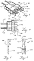
- FIG. 1 shows a solenoid valve harness assembly according to a first embodiment of the present invention.
- FIG. 2 shows the harness portion of the embodiment FIG. 1.
- FIG. 3 is a perspective view of one of the harness plugs of the embodiment of FIG. 1.
- FIG. 4 is a top view of the harness plug shown in FIG. 3.
- FIG. 5 is a side view of one of the harness plug terminals shown in FIG. 3.
- FIG. 6 is a top view of the harness plug terminal shown in FIG. 5.
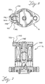
- FIG. 7 is a vertical sectional view of one of the solenoid valves of the embodiment of FIG. 1.
- FIG. 8 is a top view of the solenoid valve of FIG. 7.
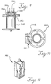
- FIG. 9 is a side view of the bobbin shown in FIG. 7.
- FIG. 10 is a top view of the bobbin shown in FIG. 9.
- FIG. 11 is a perspective view of one of the terminals located inside the receptacle housing of the solenoid valve of FIG. 7.
- FIG. 12 is a side view of a solenoid valve harness assembly according to a second embodiment of the present invention.
- FIG. 13 is a vertical sectional view of one of the solenoid valves used with the embodiment of FIG. 12.
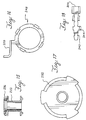
- FIG. 14 is a sectional view of the solenoid valve of FIG. 13 taken along line A-A'.
- FIG. 15 is a side view of the bobbin shown in FIG. 13.
- FIG. 16 is a top view of the ground terminal shown in FIG. 13.
- FIG. 17 is a top view of the end cap shown in FIG. 13.
- FIG. 18 is a top view of the lead terminal shown in FIG. 13.
- FIG. 19 is a side view of the solenoid coil of FIG. 13 shown partially assembled without the exterior housing in one stage of manufacture.
- FIG. 20 is an end view of the assembly of FIG. 19.
- FIG. 21 is a side view of the assembly of FIG. 19 shown in a later stage of manufacture.
- FIG. 22 is an end view of the assembly of FIG. 21.
- the embodiment shown in FIG. 1 is a solenoid harness assembly 10.
- the solenoid harness assembly 10 includes a harness portion 12 and a solenoid valve portion 14.
- the solenoid valve portion is comprised of a plurality of solenoid valves.
- the solenoid valve harness assembly 10 is used in conjunction with a transmission of a vehicle such as an automobile or truck.
- the plurality of solenoid valves 14 are mounted on a transmission valve body (not shown) which is part of the vehicle transmission.
- the transmission valve body is located inside the transmission housing or case (represented by dotted line 30).
- the solenoid valves 14 interact with other components such as spool valves which are located inside the transmission valve body.
- the plurality of solenoid valves 14 are connected via the harness 12 to a vehicle controller (not shown) which is located outside the transmission case.
- the controller sends electrical signals via the harness 12 to each of the solenoid valves 14 to effect operation of the spool valves inside the transmission valve body.
- the solenoid valves 16 and 18 are pulse width modulated solenoid valves and the solenoid valves 20 and 22 are on/off solenoid valves.
- the solenoid valves 16 and 18 may be identical to each other and the solenoid valves 20 and 22 may be identical to each other.
- the solenoid valves 18, 20, and 22 are mounted adjacent to each other on the transmission valve body and the solenoid valve 16 is also mounted on the transmission valve body but is located several inches away from the solenoid valves 18, 20, and 22. Details of these solenoid valves are set forth in U.S. Pat. No. 5,322,260, the entire disclosure of which is incorporated herein by reference.
- the harness 12 includes a plurality of lead wires 40, 42, 44, and 46.
- each of these lead wires includes a separate metallic conductor surrounded by a non-conductive plastic jacket.
- the harness 12 has four separate lead wires or conductors, one for each of the solenoid valves 14.
- the lead wires terminate in a controller plug 54 that is sized and adapted for connection to the vehicle controller (not shown). In this manner, signals from the controller can be sent to and operate each of the solenoid valves independently.
- the solenoid valves 14 are mounted on the transmission valve body which is located inside the transmission case 30 of the vehicle.
- the controller is located outside the transmission case. Therefore, the harness 12 which connects these parts extends between the inside of the transmission case 30 and the outside thereof through an opening 55 in the transmission case 30.
- the lead wires of the harness may be routed together inside a tubing, such as PVC tubing 58, or otherwise bound together.
- a tubing such as PVC tubing 58
- the four lead wires diverge and are routed to the four solenoid valves.
- two or more of the lead wires may be bound together or located inside a tubing, such as tubing 59.
- a transmission case plug 60 Located at a position along the harness 12 where the harness extends through the opening 55 in the transmission case 30 is a transmission case plug 60.
- the transmission case plug 60 is designed to prevent the flow or seepage of fluid from inside the transmission case 30 through the opening 55 in the transmission case 30 through which the harness 12 extends. Accordingly, the transmission case plug 60 includes an appropriate seal, such as an O-ring seal, along its interface with the transmission case.
- each of the lead wires of the harness is made up of two separate lengths of wire that are spliced together.
- the splice in each lead wire is located along the lead wire at the transmission case plug 60.
- each of the lead wires is size 18 gauge wire and is covered with a plastic insulative coating such as Teflon.
- each of the lead wires is size 22 gauge wire and has a high temperature resistant plastic insulative coating such as high temperature Teflon.
- a thicker gauge of wire is used for the harness lead wires outside the transmission case for higher strength and conductivity.
- a thinner gauge of wire is used for the harness lead wires inside the transmission case to minimize size and to facilitate bending and routing of the lead wires within the limited space of the transmission case.
- the insulation on each of the conductors of the lead wires is stripped back and the conductors are embedded in an insulative epoxy 61 at the location of the transmission case plug 60 where the separate lengths of each of the lead wires are spliced together.
- the epoxy 61 provides a bulkhead effect to retain fluid inside the transmission case and to prevent fluid from seeping out of the transmission case along the conductor portions of the lead wires.
- the harness 12 also includes a ground wire portion 62.
- the ground wire portion 62 is located entirely inside the transmission case.
- the ground wire portion 62 includes four ground wires 64, 66, 68, and 70.
- One end of each of the ground wires is connected to each one of the solenoid valves 16, 18, 20, and 22.
- the other ends of each of the ground wires 64, 66, 68, and 70 are directly connected to the transmission valve body which in turn is connected to the vehicle ground.
- the grounded end of the ground wire portion 62 may include a ground terminal such as eyelet 72.
- the connection between the ground wire portion 62 of the harness 12 and the transmission valve body may be made by connecting the eyelet 72 to the transmission valve body with a bolt or similar fastener. Where several of the ground wires are proximate to each other, such as the ground wires 66, 68, and 70, they may be connected together to a single ground terminal 74 which in turn may be bolted to the transmission valve body.
- connection between the harness 12 and each of the solenoid valves is made by means of a plug and receptacle arrangement.
- the plug and receptacle arrangement provides a number of advantages compared to prior solenoid valve harnesses in which the solenoid valves are soldered or welded to the harness.
- FIG. 2 shows a harness portion 12 of the solenoid harness assembly 10 without the solenoid valves.
- the harness portion 12 includes the lead wires 40, 42, 44, and 46, the ground wires 64, 66, 68, and 70, their respective plugs 80, 82, 84, and 86, the controller plug 52, the transmission case plug 60, and the grounding terminals 72 and 74. Because the harness 12 is provided as a separate component from the solenoid valves 16, 18, 20, and 22, each of these components can be tested prior to being connected together. In a preferred embodiment, the harness 12 can also be disconnected from any or all of the solenoid valves. Thus, in preferred embodiment it would be possible to replace a defective solenoid valve in the field without discarding the entire solenoid valve harness 10.
- the plug 80 includes a plug housing portion 106 that holds two terminals 108 and 110 in a side-by-side relationship.
- the plug housing 106 is made of a plastic insulative material, such as nylon, and the terminals are made of a conductive material.
- Connected to the plug housing 106 are the lead wire 40 and the ground wire 64.
- the lead and ground wires enter into the inside of the plug housing 106 via an opening in the rear side of the plug housing 106.
- the end of the lead wire 40 connects to the terminal 108 and the end of the ground wire 64 connects to the terminal 110.
- the two terminals 108 and 110 extend from a forward edge 111 of the plug body 106.
- the plug 80 also includes latching arm portions 112 and 114 that extend from the forward edge 111 of the plug housing body 106 in the same direction as the terminals 108 and 110.
- the latching arm portions 112 and 114 each have a small recess or opening, 116 and 118, respectively, located in or through the latching arm portions close to the forward edge 111 of the plug housing body 106.
- the recesses 116 and 118 serve to fix the plug 80 to its corresponding receptacle on the solenoid valve, as explained below.
- FIGS. 5 and 6 show the lead terminal 108.
- the ground terminal 110 may be identical to the lead terminal 108.
- the lead terminal 108 includes a rear portion 120 and a front portion 122.
- the rear portion 120 has upward extending sides 124 and 126.
- the connection between the lead wire 40 and the lead terminal 108 may be made by stripping the insulation from the end of the lead wire 40, pressing the bare conductor end of the lead wire into the lead terminal 108, and bending the sides 124 and 126 of the lead terminal 108 to mechanically secure the bare end of the lead wire 40 into the lead terminal 108 and to make an electrical connection between the conductive portion of lead wire 40 and the lead terminal 108.
- the front portion 122 of the lead terminal 108 includes a pair of tines 128 and 130.
- the lead terminal 108 may be a commercially available product, such as the IDC (insulation displacement connection) terminal, part no. 62898-1, available from AMP, Incorporated.
- the plug 80 is designed to mate with a receptacle on the solenoid valve 16.
- the solenoid valve 16 may be identical to the solenoid valve described in U.S. Pat. No. 5,322,260, except that this solenoid valve is modified to accommodate connection to the plug 80 of the harness.
- the solenoid valve 16 has a receptacle 100 that is matable with the plug 80 on the harness.
- the solenoid valve includes a length of wire wound around a bobbin to form a coil.
- a field is generated inside the coil to move an armature located in the bobbin.
- the armature in turn is connected to the valve body.
- the coil wire In order to pass a current through the wire that forms the coil, the coil wire must form a complete circuit.
- one end of the coil wire is connected via a lead wire of the harness to the controller and the other end of the coil wire is connected via a ground wire of the harness to the vehicle ground.
- a bobbin 140 wound with the wire coil.
- the receptacle 100 is connected to the bobbin 140 and located at a top end of the bobbin 140.
- the receptacle 100 is formed of the same piece of molded plastic material as the bobbin 140.
- the bobbin is made of nylon.
- the receptacle 100 includes a housing 142 having two ports 144 and 146.
- the port 144 houses a terminal 148 and the port 146 houses a terminal 150.
- the terminal 148 is shown in FIG. 11 and an identical terminal is used for the terminal 150.
- the ends of the coil wire connect to the receptacle terminals 148 and 150.
- Connection between the ends of the coil wire and the receptacle terminals 148 and 150 may be made by a mechanical connection or by soldering, welding, etc.
- the terminals 148 and 150 in the receptacle 100 are matable with the terminals 108 and 110 in the plug 80.
- these receptacle terminals 148 and 150 are the mating pairs, part no. 62526-1, of the IDC terminals 108 and 110.
- projections 152 and 154 Located along the outside of the receptacle housing 142 are projections 152 and 154.
- the projections 152 and 154 are ramped to form steep edges at the rear ends thereof.
- the projections 152 and 154 are sized and adapted to engage the recesses 116 and 118 of the plug 80.
- the latching arms 112 and 114 bend slightly allowing the projections 152 and 154 to slide into and engage the recesses 116 and 118.
- the edges at the rear ends of the projections 152 and 154 prevent withdrawal of the plug 80 from the receptacle 100 by pulling on the plug once they are engaged.
- the plug and receptacle arrangement for connecting the harness to the solenoid valves provides a number of advantages.
- One of the advantages relates to ease of manufacture.
- the harness and solenoid valves can be literally snapped together thereby significantly facilitating manufacture and assembly of the solenoid valve harness.
- the harness and plugs are manufactured separately from the solenoid valves.
- the manufacture of the harness including the plugs can be largely automated. Connection of the terminals inside the plugs to the lead and ground wires may be performed either by mechanical-type connections or by soldering connections that can be readily automated.
- connection of the ends of the coil wire to the terminals of the receptacle may be made by mechanical connections or by soldering operations that can be automated. Then, once the harness and solenoid valves are separately manufactured, they can be plugged together and installed on the transmission valve body of the vehicle transmission. Therefore, relatively costly operations in which the harness is separately soldered to each of the solenoid valves can be avoided.
- FIGS. 1-11 Another advantage provided by the embodiment of FIGS. 1-11 relates to quality control and yield.
- prior solenoid valve harnesses in which the harness is directly soldered to the solenoid valves, it may be difficult or relatively expensive to test each of the solenoid valves and the harness prior to connection together.
- the electrical connections may be damaged during the step of soldering the coil wires to the harness. Under such circumstance, the entire solenoid valve harness will have to be discarded.
- the step of soldering the harness to the solenoid valves is replaced with the more reliable step of plugging the harness plugs into the receptacles on the solenoid valves.
- FIGS. 1-11 the step of soldering the harness to the solenoid valves is replaced with the more reliable step of plugging the harness plugs into the receptacles on the solenoid valves.
- the defective component either one of the solenoid valves or the harness, can easily be removed and replaced. Removal of any of the solenoid valves from the harness may be accomplished by prying the latching arms away from the projections so that the plug can be removed from the receptacle.
- a further advantage relates to quality control and testing during manufacture.
- testing of each solenoid valve prior to connection to the harness is facilitated.
- a testing device may employ a plug identical to the those on the harness to easily energize the solenoid valve for testing.
- the harness can be tested separately prior to connection to any of the solenoid valves by means of a testing device that has a connector identical to the receptacle on the solenoid valves. In this way, if the harness or any the solenoid valves are defective, they will not be used in the assembly.
- a still further advantage relates to solenoid valve harness strength and durability.
- a solenoid valve of the type used for this application it is typical to provide a large number of turns in the coil. Because of this, a relatively thin wire is used for the coil wire inside the solenoid.
- the wire used for the coil is relatively fragile compared to the wires of the harness. Stresses and vibrations may be encountered by the solenoid valve harness during manufacture and operation. Because the wire used for the solenoid coil is relatively fragile, it is relatively susceptible to damage compared to the wires used in the harness. If the solenoid coil wire is damaged, the entire solenoid valve harness assembly will have to be discarded. Therefore, it would be advantageous to avoid stressing the wire of the coil and to transfer any stresses away from the coil wire toward larger, sturdier components.
- FIGS. 1-11 provides for reducing the susceptibility of damage to the coil wire.
- the plug portion of the harness connects directly to the bobbin of the solenoid valve by means of the receptacle located on the bobbin.
- the connection that is made is a mechanical connection between two relatively strong plastic components. Therefore, any physical stresses that are applied to the connection between the solenoid valves and the harness are transferred and carried by these relatively strong plastic pieces.
- the connections between the conductive components such as the connection between the conductor of the lead wire and the plug terminal or the connection between the coil wire and the receptacle terminal, are physically isolated from such stresses.
- FIGS. 12-22 show another embodiment of the present invention.
- a solenoid valve harness 200 is similar to the solenoid valve harness 10 of FIGS. 1-11 except as noted below.
- the solenoid valve harness 200 is used in a transmission of a vehicle.
- a solenoid valve harness 200 includes a harness portion 202.
- the harness 202 includes four lead wires 204, 206, 208 and 210 that connect four solenoid valves 212, 214, 216, and 218 to a controller plug 220.
- the solenoid valves are internally grounded. Specifically, one end of the coil wire is connected directly internally to the solenoid valve housing which in turn is connected to the transmission valve body and the vehicle ground. Because the solenoid valves are internally grounded, the need to provide separate ground wires from each solenoid valve is eliminated. A number of advantages are provided by this embodiment, as explained below.
- FIGS. 13 and 14 show an embodiment of a solenoid valve 212 that is used in the solenoid valve harness 200 of FIG. 12.
- a wire is wound on a bobbin 222 to form a coil 224.
- the coil 224 is enclosed inside a solenoid valve housing 226.
- the solenoid valve housing 226 includes three parts: a cylindrically-shaped housing body 228, a housing cover 230, and an end cap 232 opposite the housing cover 230.
- the end cap is made of magnetic iron F-0000-45P having a density of 7 g/cc.
- the solenoid valve 212 is mounted onto the transmission valve body by bolting the housing cover 230 onto the transmission valve body.
- Apertures 234 in a flange portion of the housing cover 230 are provided for this purpose.
- the housing body 228 may be connected to the housing cover 230 by the welding process described in U.S. Pat. No. 5,322,260.
- the end cap 232 may be connected to the housing body 228 by the process described in the aforementioned patent.
- the end cap 232 is shown in FIG. 17. When the housing body 228, housing cover 230, and end cap 232 are assembled, a continuous electrical path is formed between the end cap 232 and the housing cover 230 through the housing body 228.
- the lead wire 204 enters into a port 236 of the solenoid valve 212.
- the port 236 is formed as part of the bobbin 222 and body 228.
- the lead wire 204 extends through a channel 238 formed in the top end of the bobbin 222.
- the insulation at the end of the lead wire 204 is stripped back and a lead terminal 240 is connected onto the conductive portion of the lead wire 204.
- the lead terminal 240 may be made of a suitable conductive material such as a tin plated half hard brass.
- the lead terminal 240 is shown in FIG. 18. Extending into the channel 238 from an opening located at the other end of the channel away from the port 236 is one end 242 of the coil wire.
- This end 242 of the coil wire is connected onto the lead terminal 240 of the lead wire.
- the end 242 of the coil wire is wound around a lead terminal post 244 of the lead terminal 240 and soldered or welded onto the lead terminal post 244. This melts away the insulation on the end 242 of the coil wire and provides for making an electrical connection between the coil wire and the lead terminal 240.
- winding of the end 242 of the coil wire onto the lead terminal post 244 and soldering these parts together is performed by automated processes as known in the art.
- the other end of the coil wire is connected to ground.
- the second end 246 of the coil wire is connected to a ring-shaped ground terminal 248.
- This ring-shaped ground terminal 248 is located inside the solenoid valve housing 226 close to the top end of the bobbin 222.
- the ground terminal 248 is made of a conductive material, such as tin coated half hard brass.
- Located on the ground terminal 248 is a ground terminal post 250.
- the ground terminal post 250 extends into a notch 252 at the top of the bobbin 222.
- the second end 246 of the coil wire is wound onto the ground wire post 250 and soldered to it to remove the insulation on the end of the coil wire and to make a secure electrical connection between the ground terminal 248 and the second end 246 of the coil wire.
- the spring 254 Located between the ring-shaped ground terminal 248 and the end cap 232 is a small spring 254.
- the spring 254 has a diameter corresponding to the size of the ring-shaped ground terminal 248.
- the spring 254 is made of an electrically conductive material, such as music wire or stainless steel wire.
- An electrical conduction path is established between the second end 246 of the coil wire, the ring-shaped ground terminal 248, the spring 254, the end cap 232, the housing body 228, and the housing cover 230 to ground.
- the lead terminal post 244 on the lead terminal 240 and the ground terminal post 250 on the ring-shaped ground terminal 248 can be formed to have an initial shape as shown in FIGS. 20 and 21.
- the first end of the coil wire 242 is wound onto the lead terminal post 244 of the lead wire terminal 240 and the second end 246 of the coil wire is wound onto the ground terminal post 250 of the ring-shaped ground terminal 248.
- the ends 242 and 246 of the coil wire are then soldered onto the posts 244 and 250, respectively.
- the lead terminal post 244 of lead wire terminal 240 is bent downward and the ground terminal post 250 of the ground wire terminal 248 is bent downward, as shown in FIGS. 21 and 22.
- the lead wire 204 and lead wire terminal 240 are pressed into the channel 238 on the top of the bobbin 22.
- the spring 254 and end cap 232 are positioned onto the bobbin 222 and the tabs 258 of the housing body 238 are bent over the end cap 232 thereby securing the end cap 232 onto the housing body 228. This also results in completing the electrical ground connection between the second end 246 of the coil wire and the cover 230 of the solenoid valve.
- the embodiment of the solenoid valve harness shown in FIGS. 12-22 provides a number of advantages. First of all, because the solenoid valves are internally grounded, the expense of the separate ground wire portion of the harness is eliminated.
- a further advantage that follows from the elimination of the ground wires is that there is more room for the lead wires 204, 206, 208, and 210. Because there is more room for the lead wires, the need to use a smaller gauge wire for the lead wires inside the transmission case may also be avoided. This permits the same gauge wire to be used for the lead wires both inside and outside the transmission case thereby avoiding the need to splice together difference sizes of wires, as in prior solenoid valve harnesses.
- each lead wire 204, 206, 208, and 210 is formed of a continuous piece of wire without any splices. In the location of the transmission case plug 260, a portion of the insulation is removed from each of the lead wires so that the lead wire conductors can be embedded in an epoxy 262 to prevent seepage from the transmission case.
- each of the lead wires 204, 206, 208, and 210 has a high temperature insulative jacket suitable for use inside the transmission case. Since single, continuous lengths of wire are used in this embodiment instead of separate lengths of wire spliced together, a high temperature resistant, insulative nonconductive jacket is provided on the lead wires both inside and outside the transmission case.
- the embodiment of the solenoid valve harness in FIGS. 12-22 may be formed with a plug and receptacle arrangement as in the embodiment shown in FIGS. 1-11. If a plug and receptacle arrangement is used for the embodiment of FIGS. 12-22, the plugs and receptacles need to provide for connection of the lead wires only since the solenoid valves are internally grounded. In a present embodiment, the solenoid valve harness of FIGS. 12-22 are formed without a plug and receptacle arrangement.
Landscapes
- Engineering & Computer Science (AREA)
- General Engineering & Computer Science (AREA)
- Mechanical Engineering (AREA)
- Physics & Mathematics (AREA)
- Electromagnetism (AREA)
- Magnetically Actuated Valves (AREA)
- Control Of Transmission Device (AREA)
Applications Claiming Priority (2)
| Application Number | Priority Date | Filing Date | Title |
|---|---|---|---|
| US352279 | 1982-02-25 | ||
| US08/352,279 US5558311A (en) | 1994-12-08 | 1994-12-08 | Solenoid valve harness |
Publications (2)
| Publication Number | Publication Date |
|---|---|
| EP0716249A2 true EP0716249A2 (fr) | 1996-06-12 |
| EP0716249A3 EP0716249A3 (fr) | 1997-07-16 |
Family
ID=23384494
Family Applications (1)
| Application Number | Title | Priority Date | Filing Date |
|---|---|---|---|
| EP95306151A Withdrawn EP0716249A3 (fr) | 1994-12-08 | 1995-09-04 | Faisceau pour vanne électromagnétique |
Country Status (2)
| Country | Link |
|---|---|
| US (1) | US5558311A (fr) |
| EP (1) | EP0716249A3 (fr) |
Cited By (2)
| Publication number | Priority date | Publication date | Assignee | Title |
|---|---|---|---|---|
| FR2763376A1 (fr) * | 1997-05-14 | 1998-11-20 | Toyoda Automatic Loom Works | Soupape de commande d'un compresseur a deplacement variable pour climatiseur d'air de vehicule, et compresseur comprenant une telle soupape |
| EP2607653A3 (fr) * | 2011-12-22 | 2017-10-11 | Rolls-Royce plc | Ensemble de câblage électrique avec plan de masse pour moteurs à turbine à gaz |
Families Citing this family (13)
| Publication number | Priority date | Publication date | Assignee | Title |
|---|---|---|---|---|
| US6038918A (en) * | 1997-12-22 | 2000-03-21 | William T. Newton | Instrument for testing automatic transmission fluid control devices |
| US6029703A (en) * | 1998-12-18 | 2000-02-29 | Borg-Warner Automotive, Inc. | Pressure solenoid control valve with flux shunt |
| US7051993B2 (en) * | 2004-03-10 | 2006-05-30 | Eaton Corporation | Solenoid operated valve and method of making same |
| US7076997B2 (en) * | 2004-05-12 | 2006-07-18 | Honda Motor Co., Ltd. | Apparatus for testing automatic transmission solenoid valves |
| US7497203B2 (en) * | 2005-08-03 | 2009-03-03 | Caterpillar Inc. | Avoidance of spark damage on valve members |
| US8002206B2 (en) * | 2006-12-29 | 2011-08-23 | Caterpillar Inc. | Avoidance of spark damage on valve members |
| US8025522B2 (en) * | 2008-10-31 | 2011-09-27 | Anthony Freakes | Insulation displacement connector |
| JP5980034B2 (ja) * | 2012-07-31 | 2016-08-31 | 日立オートモティブシステムズ株式会社 | 緩衝器 |
| US10591081B2 (en) * | 2016-04-01 | 2020-03-17 | Emerson Electric Co. | Solenoid coil including bobbin with moisture barrier |
| US10240684B2 (en) * | 2016-06-23 | 2019-03-26 | Hamilton Sundstrand Corporation | Valve assembly having a manual override unit |
| KR101947904B1 (ko) * | 2017-06-05 | 2019-02-13 | 주식회사 현대케피코 | 솔레노이드밸브 벤트 구조 |
| US11307115B2 (en) * | 2019-03-10 | 2022-04-19 | Automatic Switch Company | Valve test connection |
| US20230072117A1 (en) * | 2020-05-28 | 2023-03-09 | Zhejiang Dunan Artificial Environment Co., Ltd. | Solenoid Valve Coil |
Citations (1)
| Publication number | Priority date | Publication date | Assignee | Title |
|---|---|---|---|---|
| US5322260A (en) | 1993-05-24 | 1994-06-21 | Borg-Warner Automotive, Inc. | Solenoid valve |
Family Cites Families (7)
| Publication number | Priority date | Publication date | Assignee | Title |
|---|---|---|---|---|
| DE3024894A1 (de) * | 1980-07-01 | 1982-01-28 | Concordia Fluidtechnik Gmbh, 7000 Stuttgart | Elektromagnetteil zum anschlug an eine geraetesteckvorrichtung |
| JPS61136071A (ja) * | 1984-12-01 | 1986-06-23 | Aisin Seiki Co Ltd | 電磁弁 |
| DE3500785A1 (de) * | 1985-01-11 | 1986-07-17 | Nass Magnet Gmbh, 3000 Hannover | Mit kunststoff ummantelte spule |
| JPS63147978A (ja) * | 1986-12-09 | 1988-06-20 | Nippon Denso Co Ltd | 圧縮機用ソレノイドバルブ |
| DE3816750C2 (de) * | 1988-05-17 | 1996-05-23 | Teves Gmbh Alfred | Elektrohydraulisches Ventilblockaggregat |
| DE4001017A1 (de) * | 1990-01-16 | 1991-07-18 | Bosch Gmbh Robert | Montageeinheit aus einem ventilblockaggregat sowie einem steuergeraet |
| JP2698722B2 (ja) * | 1991-10-22 | 1998-01-19 | シーケーディ株式会社 | 電磁弁 |
-
1994
- 1994-12-08 US US08/352,279 patent/US5558311A/en not_active Expired - Fee Related
-
1995
- 1995-09-04 EP EP95306151A patent/EP0716249A3/fr not_active Withdrawn
Patent Citations (1)
| Publication number | Priority date | Publication date | Assignee | Title |
|---|---|---|---|---|
| US5322260A (en) | 1993-05-24 | 1994-06-21 | Borg-Warner Automotive, Inc. | Solenoid valve |
Cited By (2)
| Publication number | Priority date | Publication date | Assignee | Title |
|---|---|---|---|---|
| FR2763376A1 (fr) * | 1997-05-14 | 1998-11-20 | Toyoda Automatic Loom Works | Soupape de commande d'un compresseur a deplacement variable pour climatiseur d'air de vehicule, et compresseur comprenant une telle soupape |
| EP2607653A3 (fr) * | 2011-12-22 | 2017-10-11 | Rolls-Royce plc | Ensemble de câblage électrique avec plan de masse pour moteurs à turbine à gaz |
Also Published As
| Publication number | Publication date |
|---|---|
| US5558311A (en) | 1996-09-24 |
| EP0716249A3 (fr) | 1997-07-16 |
Similar Documents
| Publication | Publication Date | Title |
|---|---|---|
| US5558311A (en) | Solenoid valve harness | |
| US5735695A (en) | Electrical cable connecting device | |
| EP0650226B1 (fr) | Unité moulée de composants de circuit pour la connexion de fils conducteurs et méthode de production de celle-ci | |
| US5716236A (en) | System for terminating the shield of a high speed cable | |
| US5725387A (en) | System for terminating the shield of a high speed cable | |
| EP0600418A1 (fr) | Connecteur de coussin gonflable court circuité | |
| EP1003250A1 (fr) | Un connecteur blindé, un jeu de connecteurs blindés et procédé pour connecter un connecteur blindé avec un câble blindé | |
| US20200254944A1 (en) | Harness component | |
| US10998652B2 (en) | Shield terminal | |
| US7851955B2 (en) | Coil connecting structure, coil connecting method, set of conductors, and electric motor | |
| KR20010080181A (ko) | 전기 터미널을 포함하는 구성 부품을 전기 회로와접속하기 위한 구성 | |
| US7297029B2 (en) | Communication control IC-incorporating connector and wiring harness with communication control IC-incorporating connector | |
| US5888088A (en) | Electrical connection construction of electrical connection box | |
| JPS6224582A (ja) | 電気コネクタ | |
| EP0525249B1 (fr) | Connecteur électrique et procédé pour la connexion d'un cable blindé à celui-ci | |
| EP0881717B1 (fr) | Fiche électrique | |
| US5957548A (en) | Electrohydraulic unit for regulating brake pressure in a motor vehicle brake system | |
| US20070197094A1 (en) | Contacts For Use In Monitoring Connection Patterns In Data Ports | |
| WO2009142273A1 (fr) | Élément de connexion | |
| EP0128455B1 (fr) | Feu pour véhicules | |
| JP3289573B2 (ja) | 自動車用ワイヤハーネスと負荷部品との接続構造 | |
| CN115693188A (zh) | 带用于快速idc连接的模块化结构的绝缘刺破式连接器 | |
| EP0503380B1 (fr) | Système avec connecteur électrique | |
| JP7626661B2 (ja) | 通信コネクタ | |
| EP1003244B1 (fr) | Connecteur blindé et procedé pour connecter un connecteur blindé avec un câble blindé |
Legal Events
| Date | Code | Title | Description |
|---|---|---|---|
| PUAI | Public reference made under article 153(3) epc to a published international application that has entered the european phase |
Free format text: ORIGINAL CODE: 0009012 |
|
| AK | Designated contracting states |
Kind code of ref document: A2 Designated state(s): DE FR GB |
|
| PUAL | Search report despatched |
Free format text: ORIGINAL CODE: 0009013 |
|
| AK | Designated contracting states |
Kind code of ref document: A3 Designated state(s): DE FR GB |
|
| 17P | Request for examination filed |
Effective date: 19971119 |
|
| STAA | Information on the status of an ep patent application or granted ep patent |
Free format text: STATUS: THE APPLICATION HAS BEEN WITHDRAWN |
|
| 18W | Application withdrawn |
Withdrawal date: 19980313 |