EP0716488A2 - Raccordement électrique à haute tension - Google Patents
Raccordement électrique à haute tension Download PDFInfo
- Publication number
- EP0716488A2 EP0716488A2 EP95118044A EP95118044A EP0716488A2 EP 0716488 A2 EP0716488 A2 EP 0716488A2 EP 95118044 A EP95118044 A EP 95118044A EP 95118044 A EP95118044 A EP 95118044A EP 0716488 A2 EP0716488 A2 EP 0716488A2
- Authority
- EP
- European Patent Office
- Prior art keywords
- plug contact
- voltage plug
- contact according
- coupling point
- cable connection
- Prior art date
- Legal status (The legal status is an assumption and is not a legal conclusion. Google has not performed a legal analysis and makes no representation as to the accuracy of the status listed.)
- Granted
Links
Images



Classifications
-
- H—ELECTRICITY
- H02—GENERATION; CONVERSION OR DISTRIBUTION OF ELECTRIC POWER
- H02B—BOARDS, SUBSTATIONS OR SWITCHING ARRANGEMENTS FOR THE SUPPLY OR DISTRIBUTION OF ELECTRIC POWER
- H02B13/00—Arrangement of switchgear in which switches are enclosed in, or structurally associated with, a casing, e.g. cubicle
- H02B13/005—Electrical connection between switchgear cells
-
- H—ELECTRICITY
- H01—ELECTRIC ELEMENTS
- H01R—ELECTRICALLY-CONDUCTIVE CONNECTIONS; STRUCTURAL ASSOCIATIONS OF A PLURALITY OF MUTUALLY-INSULATED ELECTRICAL CONNECTING ELEMENTS; COUPLING DEVICES; CURRENT COLLECTORS
- H01R13/00—Details of coupling devices of the kinds covered by groups H01R12/70 or H01R24/00 - H01R33/00
- H01R13/46—Bases; Cases
- H01R13/53—Bases or cases for heavy duty; Bases or cases for high voltage with means for preventing corona or arcing
-
- H—ELECTRICITY
- H02—GENERATION; CONVERSION OR DISTRIBUTION OF ELECTRIC POWER
- H02B—BOARDS, SUBSTATIONS OR SWITCHING ARRANGEMENTS FOR THE SUPPLY OR DISTRIBUTION OF ELECTRIC POWER
- H02B13/00—Arrangement of switchgear in which switches are enclosed in, or structurally associated with, a casing, e.g. cubicle
- H02B13/02—Arrangement of switchgear in which switches are enclosed in, or structurally associated with, a casing, e.g. cubicle with metal casing
- H02B13/035—Gas-insulated switchgear
- H02B13/0356—Mounting of monitoring devices, e.g. current transformers
Definitions
- the invention relates to a high-voltage plug contact for installation in a housing, preferably a converter housing, in particular as a counterpart to an outer cone cable connection according to DIN 47636 of a switchgear.
- G 90 12 016 design the measuring transducer to be pluggable directly, an outer cone being provided on the transducer for this purpose.
- the transducer can be designed as a voltage or current transformer.
- the object of the invention is to provide a partially discharge-proof connector.
- a conventional transducer with a rectangular transducer body can be changed by changing the shape of the transducer body, e.g. claims 10 to 13 to be adaptable to the requirements of the invention.
- Figure 1 shows a transducer 1, which is arranged at the location of an outer cone cable connection 2, of a switchgear with a housing 3.
- Switchgear 3 can be, for example, a gas-insulated switchgear.
- the transducer 1 is arranged directly on the housing of the switchgear 3 within the cable room or directly on the busbars.
- FIG 2 shows the switchgear according to Figure 1 from a view from above.
- the switchgear has three outer cone cable connections 2, which are arranged in a row. All three outer cone cable connections 2 are occupied by transducers 1. In this view, the space-saving shape of the transducer 1 can be clearly seen.
- the converter body 4 is designed to be screwed directly onto the housing of the switchgear 3.
- the converter body 4 is designed to deviate from the rectangular shape on the sides of the other outer cone cable connections 2, so that the other outer cone cable connections 2 are freely accessible.
- the deviation from the rectangular shape is e.g. given by a slant. Since, in the present example, a plurality of outer cone cable connections are arranged in series, the converter body 4 has a projection e.g. like a triangle. Furthermore, a connector 6 for the secondary-side measurement signal is provided on the transducer body 4, to which a measurement line can be connected.
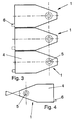
- Figure 3 shows a parallel arrangement of transducers 1 on the switchgear.
- Figure 4 shows a transducer 1 from Figure 2 with a view of the signal coupling point 5.
- the triangular projection has an angle ⁇ , which corresponds to the installation on the system.
- the angle ⁇ is 40 °.
- the transducer 1 has a signal coupling point 5 which, when the converter body 4 is arranged on the housing of the switchgear assembly 3, matches an electrical signal coupling point of the outer cone cable connection 2.
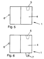
- FIG. 5 shows a transducer 1 in which the signal coupling point 5 is an electrical contact, in particular a plug-in part.
- the transducer 1 is designed in this embodiment as a voltage converter.
- FIG. 6 shows a transducer 1 in the form of the transducer from FIG. 5, in which, in addition to the signal coupling point 5, a signal coupling point 7 is arranged on the opposite side.
- the signal coupling point 5 and the signal coupling point 7 are connected to one another in an electrically conductive manner within the transducer 1.
- the measuring transformer 1 it is also possible to design the measuring transformer 1 as a current transformer.
- the primary winding of a measuring core can be connected between signal input 5 and signal output 7.
- Figure 7 shows a section through the plug contact connection according to the invention.
- an outer cone part according to DIN 47636 is shown. It consists of an outer insulating plastic sheath 12 with an inner, centrally arranged, high-voltage metallic conductor 13.
- two fastening options of this outer cone part 11 are shown. Either it can be welded to a plate-shaped collar 14 with the housing 15 of the switchgear carrying earth potential, or it can be conductively connected as a casting with a casting bushing 16 for ground control.
- the housing of a voltage converter is identified by 17, in which a trough 18 is provided in the insulating casting compound 19. At the bottom of the trough 18, a potential-carrying contact 20 is cast, from which the potential can be tapped by a cable connection, not shown. At the upper end of part 20 is a spring 22 by means of a screw 21 attached, which presses conductive against the front end of the conductor 13 and thus enables the potential tap.
- a pin can also be fastened which engages in the cylindrical bush 23 and in this way establishes the conductive connection.
- the elastic insulating part 24 is made of silicone rubber and has a lower control electrode 25 at the front lower end and an upper control electrode 26 at the upper end.
- the control electrodes 25, 26 are ring-shaped and have a conical shape as a cross section, the cone tips 27, 28 being rounded. Towards the center, this curve merges into a side wall 30 or 31 which is approximately parallel to the axis 29.
- the side walls 30, 31 change their diameter abruptly, so that they form shoulders 32 and 33. Shoulder 33 bears against outer cone part 11 when inserted, while shoulder 32 bears against cast-in potential-carrying contact 20. Vent channels 34 and 35 are provided both in the potential-carrying contact 20 and in the elastic insulating part 24, which provide ventilation when the plug is inserted or removed.
- the lower control electrode 25 receives the potential of the cast-in potential-carrying contact 20 via the shoulder 32, while contact with the earth potential of the converter housing 17 is established by contacting the upper control electrode 26 with the upwardly curved edge of the converter housing 17.
- transducer 1 has a signal decoupling point 7 which can be connected directly to the outer cone cable connection in accordance with DIN 46737 of the switchgear in order to take off the electrical signal.
Landscapes
- Engineering & Computer Science (AREA)
- Power Engineering (AREA)
- Cable Accessories (AREA)
- Connector Housings Or Holding Contact Members (AREA)
- Coupling Device And Connection With Printed Circuit (AREA)
- Patch Boards (AREA)
Applications Claiming Priority (2)
| Application Number | Priority Date | Filing Date | Title |
|---|---|---|---|
| DE4445082 | 1994-12-08 | ||
| DE4445082A DE4445082C1 (de) | 1994-12-08 | 1994-12-08 | Hochspannungs-Steckkontakt |
Publications (3)
| Publication Number | Publication Date |
|---|---|
| EP0716488A2 true EP0716488A2 (fr) | 1996-06-12 |
| EP0716488A3 EP0716488A3 (fr) | 1997-02-19 |
| EP0716488B1 EP0716488B1 (fr) | 1999-07-14 |
Family
ID=6536128
Family Applications (1)
| Application Number | Title | Priority Date | Filing Date |
|---|---|---|---|
| EP95118044A Expired - Lifetime EP0716488B1 (fr) | 1994-12-08 | 1995-11-16 | Raccordement électrique à haute tension |
Country Status (4)
| Country | Link |
|---|---|
| EP (1) | EP0716488B1 (fr) |
| AT (1) | ATE182233T1 (fr) |
| DE (2) | DE4445082C1 (fr) |
| ES (1) | ES2137439T3 (fr) |
Cited By (1)
| Publication number | Priority date | Publication date | Assignee | Title |
|---|---|---|---|---|
| EP0856925A3 (fr) * | 1997-01-28 | 1999-09-22 | AEG Sachsenwerk GmbH | Convertisseur de tension |
Families Citing this family (5)
| Publication number | Priority date | Publication date | Assignee | Title |
|---|---|---|---|---|
| DE19715825A1 (de) * | 1997-04-16 | 1998-10-22 | Kg Ritz Messwandler Gmbh & Co | Spannungswandler |
| EP2254209B1 (fr) | 2009-05-20 | 2019-08-14 | ABB Schweiz AG | Connexions de sortie primaires enfichables de deux modules d'une installation de commutation haute tension à isolation gazeuse |
| RU2541520C2 (ru) | 2009-05-20 | 2015-02-20 | Абб Текнолоджи Аг | Разъемные первичные силовые соединения двух модулей газоизолированного высоковольтного распределительного устройства |
| EP2346053B1 (fr) | 2010-01-18 | 2016-06-15 | ABB Technology AG | Unité de mesure haute tension isolée du gaz |
| DE102024203199A1 (de) * | 2024-04-09 | 2025-10-09 | Siemens Energy Global GmbH & Co. KG | Verbindungsvorrichtung zum Verbinden elektrischer Leiter |
Family Cites Families (12)
| Publication number | Priority date | Publication date | Assignee | Title |
|---|---|---|---|---|
| US4417736A (en) * | 1978-01-16 | 1983-11-29 | Amp Incorporated | High voltage rack and panel connector |
| US4222625A (en) * | 1978-12-28 | 1980-09-16 | Amerace Corporation | High voltage electrical connector shield construction |
| DE3211119C2 (de) * | 1982-03-26 | 1985-01-17 | Karl Pfisterer Elektrotechnische Spezialartikel Gmbh & Co Kg, 7000 Stuttgart | Vorrichtung zur Herstellung einer elektrisch leitenden Verbindung zwischen einer isolierten zylindrischen Sammelschiene und Kabeln eines Mittelspannungs- oder Hochspannungsenergieversorgungsnetzes |
| DE3481882D1 (de) * | 1983-11-30 | 1990-05-10 | Toshiba Kk | Gekapselte schaltanlagen. |
| DE8502491U1 (de) * | 1985-01-31 | 1986-07-17 | Karl Pfisterer Elektrotechnische Spezialartikel Gmbh & Co Kg, 7000 Stuttgart | Muffe |
| DE3538193A1 (de) * | 1985-10-26 | 1987-04-30 | Pfisterer Elektrotech Karl | Steckverbindungssystem fuer komponenten von mittelspannungs- und hochspannungsenergieversorgungsnetzen |
| DE3935360A1 (de) * | 1989-10-24 | 1991-04-25 | Pfisterer Elektrotech Karl | Isolierkoerper fuer kabelstecker, kabelendverschluesse und dergleichen |
| DE9012016U1 (de) * | 1990-08-20 | 1991-12-19 | Siemens AG, 8000 München | Meßwandler für eine Schaltanlage |
| JP2866473B2 (ja) * | 1990-11-20 | 1999-03-08 | 昭和電線電纜株式会社 | ケーブルプラグ |
| DE4239648A1 (de) * | 1992-11-26 | 1994-06-01 | Pfisterer Elektrotech Karl | Steckverbindungseinrichtung für Kabel |
| DE4312618A1 (de) * | 1993-04-19 | 1994-10-20 | Abb Patent Gmbh | Kabelsteckbuchse |
| DE9420191U1 (de) * | 1994-12-05 | 1995-02-09 | Siemens AG, 80333 München | Anordnung eines Spannungswandlers außerhalb einer metallgekapselten Leistungsschalter-Anlage |
-
1994
- 1994-12-08 DE DE4445082A patent/DE4445082C1/de not_active Expired - Fee Related
-
1995
- 1995-11-16 AT AT95118044T patent/ATE182233T1/de active
- 1995-11-16 ES ES95118044T patent/ES2137439T3/es not_active Expired - Lifetime
- 1995-11-16 DE DE59506384T patent/DE59506384D1/de not_active Expired - Lifetime
- 1995-11-16 EP EP95118044A patent/EP0716488B1/fr not_active Expired - Lifetime
Cited By (1)
| Publication number | Priority date | Publication date | Assignee | Title |
|---|---|---|---|---|
| EP0856925A3 (fr) * | 1997-01-28 | 1999-09-22 | AEG Sachsenwerk GmbH | Convertisseur de tension |
Also Published As
| Publication number | Publication date |
|---|---|
| EP0716488B1 (fr) | 1999-07-14 |
| ATE182233T1 (de) | 1999-07-15 |
| DE4445082C1 (de) | 1996-05-09 |
| ES2137439T3 (es) | 1999-12-16 |
| DE59506384D1 (de) | 1999-08-19 |
| EP0716488A3 (fr) | 1997-02-19 |
Similar Documents
| Publication | Publication Date | Title |
|---|---|---|
| DE2656694A1 (de) | Abgriffsverbindungskasten fuer kabelfernsehen | |
| EP0199891A2 (fr) | Dispositif de connexion pour des installations de commutation à isolation gazeuse | |
| EP3185365B1 (fr) | Rail d'alimentation | |
| DE4445082C1 (de) | Hochspannungs-Steckkontakt | |
| DE69022071T2 (de) | Kabelverbinder. | |
| DE19855528A1 (de) | Kapazitiver Spannungsteiler | |
| DE69401800T2 (de) | Mehrzweckstromdurchführung | |
| DE19704437A1 (de) | Steckverbindung für elektrische Leitungen | |
| EP0875971B1 (fr) | Installation de distribution électrique pour haute tension | |
| DE9113013U1 (de) | Kompensator | |
| EP2846336B1 (fr) | Connexion d'au moins quatre conducteurs électriques | |
| CH689029A5 (de) | Sicherheitssteckverbindung mit einem Sicherheitsstecker und einer Sicherheitsbuchse mit durchgehender Isolation. | |
| DE8021913U1 (de) | Bausatz für eine Kabelverbindungsstelle mit Überspannungsschutz zum Einbau in Verbindungsmuffen | |
| EP0856925A2 (fr) | Convertisseur de tension | |
| EP0191943B1 (fr) | Barrette à bornes | |
| EP1116304B1 (fr) | Raccords en t pour dispositifs de commutation moyenne tension avec isolation des gaz | |
| DE9012016U1 (de) | Meßwandler für eine Schaltanlage | |
| DE19530163C2 (de) | Hochspannungsausleitungs- und -durchführungsanordnung für Transformatoren oder Drosselspulen | |
| DE2847376C2 (de) | Ein- oder mehrpolige Trennschalteranordnung für gekapselte Schaltanlagen | |
| DE19958782B4 (de) | Durchführungsstützer und -stromwandler für metallgekapselte, luftisolierte Mittelspannungs-Schaltanlagen | |
| DE19510659C1 (de) | Anordnung zur Ankopplung eines Rundsteuersenders | |
| WO1995024723A1 (fr) | Transformateur de courant | |
| DE2743306C2 (de) | Kabel-Trenn-Endverschluß für Fernmeldeluftkabel | |
| CH662009A5 (de) | Transformatoren-unterstation. | |
| DE1930988C3 (de) | Mehrphasige Innenraumschaltanlage für Hochspannung über 30 kV |
Legal Events
| Date | Code | Title | Description |
|---|---|---|---|
| PUAI | Public reference made under article 153(3) epc to a published international application that has entered the european phase |
Free format text: ORIGINAL CODE: 0009012 |
|
| AK | Designated contracting states |
Kind code of ref document: A2 Designated state(s): AT BE CH DE ES FR GB IT LI |
|
| PUAL | Search report despatched |
Free format text: ORIGINAL CODE: 0009013 |
|
| AK | Designated contracting states |
Kind code of ref document: A3 Designated state(s): AT BE CH DE ES FR GB IT LI |
|
| 17P | Request for examination filed |
Effective date: 19970319 |
|
| 17Q | First examination report despatched |
Effective date: 19980415 |
|
| GRAG | Despatch of communication of intention to grant |
Free format text: ORIGINAL CODE: EPIDOS AGRA |
|
| GRAG | Despatch of communication of intention to grant |
Free format text: ORIGINAL CODE: EPIDOS AGRA |
|
| GRAH | Despatch of communication of intention to grant a patent |
Free format text: ORIGINAL CODE: EPIDOS IGRA |
|
| ITF | It: translation for a ep patent filed | ||
| GRAH | Despatch of communication of intention to grant a patent |
Free format text: ORIGINAL CODE: EPIDOS IGRA |
|
| GRAA | (expected) grant |
Free format text: ORIGINAL CODE: 0009210 |
|
| AK | Designated contracting states |
Kind code of ref document: B1 Designated state(s): AT BE CH DE ES FR GB IT LI |
|
| REF | Corresponds to: |
Ref document number: 182233 Country of ref document: AT Date of ref document: 19990715 Kind code of ref document: T |
|
| REG | Reference to a national code |
Ref country code: CH Ref legal event code: EP |
|
| REF | Corresponds to: |
Ref document number: 59506384 Country of ref document: DE Date of ref document: 19990819 |
|
| REG | Reference to a national code |
Ref country code: CH Ref legal event code: NV Representative=s name: PATENTSANWALTSBUERO RENFER-VONNEMANN |
|
| ET | Fr: translation filed | ||
| GBT | Gb: translation of ep patent filed (gb section 77(6)(a)/1977) |
Effective date: 19990914 |
|
| REG | Reference to a national code |
Ref country code: ES Ref legal event code: FG2A Ref document number: 2137439 Country of ref document: ES Kind code of ref document: T3 |
|
| PLBE | No opposition filed within time limit |
Free format text: ORIGINAL CODE: 0009261 |
|
| STAA | Information on the status of an ep patent application or granted ep patent |
Free format text: STATUS: NO OPPOSITION FILED WITHIN TIME LIMIT |
|
| 26N | No opposition filed | ||
| REG | Reference to a national code |
Ref country code: GB Ref legal event code: IF02 |
|
| REG | Reference to a national code |
Ref country code: CH Ref legal event code: PCAR Representative=s name: PATENTANWALTSBUERO URSULA RENFER-VONNEMANN; ROSWIESENSTRASSE 61; 8309 BIRCHWIL-NUERENSDORF (CH) |
|
| REG | Reference to a national code |
Ref country code: CH Ref legal event code: NV Representative=s name: KATZAROV S.A. |
|
| PGFP | Annual fee paid to national office [announced via postgrant information from national office to epo] |
Ref country code: CH Payment date: 20121123 Year of fee payment: 18 |
|
| PGFP | Annual fee paid to national office [announced via postgrant information from national office to epo] |
Ref country code: IT Payment date: 20121122 Year of fee payment: 18 Ref country code: ES Payment date: 20121122 Year of fee payment: 18 Ref country code: GB Payment date: 20121122 Year of fee payment: 18 Ref country code: BE Payment date: 20121129 Year of fee payment: 18 |
|
| PGFP | Annual fee paid to national office [announced via postgrant information from national office to epo] |
Ref country code: AT Payment date: 20121122 Year of fee payment: 18 Ref country code: FR Payment date: 20121217 Year of fee payment: 18 |
|
| PGFP | Annual fee paid to national office [announced via postgrant information from national office to epo] |
Ref country code: DE Payment date: 20130124 Year of fee payment: 18 |
|
| BERE | Be: lapsed |
Owner name: *RITZ MESSWANDLER G.M.B.H. & CO. K.G. Effective date: 20131130 |
|
| REG | Reference to a national code |
Ref country code: CH Ref legal event code: PL |
|
| REG | Reference to a national code |
Ref country code: AT Ref legal event code: MM01 Ref document number: 182233 Country of ref document: AT Kind code of ref document: T Effective date: 20131116 |
|
| GBPC | Gb: european patent ceased through non-payment of renewal fee |
Effective date: 20131116 |
|
| PG25 | Lapsed in a contracting state [announced via postgrant information from national office to epo] |
Ref country code: CH Free format text: LAPSE BECAUSE OF NON-PAYMENT OF DUE FEES Effective date: 20131130 Ref country code: LI Free format text: LAPSE BECAUSE OF NON-PAYMENT OF DUE FEES Effective date: 20131130 |
|
| REG | Reference to a national code |
Ref country code: FR Ref legal event code: ST Effective date: 20140731 |
|
| REG | Reference to a national code |
Ref country code: DE Ref legal event code: R119 Ref document number: 59506384 Country of ref document: DE Effective date: 20140603 |
|
| PG25 | Lapsed in a contracting state [announced via postgrant information from national office to epo] |
Ref country code: DE Free format text: LAPSE BECAUSE OF NON-PAYMENT OF DUE FEES Effective date: 20140603 Ref country code: IT Free format text: LAPSE BECAUSE OF NON-PAYMENT OF DUE FEES Effective date: 20131116 Ref country code: AT Free format text: LAPSE BECAUSE OF NON-PAYMENT OF DUE FEES Effective date: 20131116 |
|
| PG25 | Lapsed in a contracting state [announced via postgrant information from national office to epo] |
Ref country code: BE Free format text: LAPSE BECAUSE OF NON-PAYMENT OF DUE FEES Effective date: 20131130 |
|
| PG25 | Lapsed in a contracting state [announced via postgrant information from national office to epo] |
Ref country code: GB Free format text: LAPSE BECAUSE OF NON-PAYMENT OF DUE FEES Effective date: 20131116 Ref country code: FR Free format text: LAPSE BECAUSE OF NON-PAYMENT OF DUE FEES Effective date: 20131202 |
|
| REG | Reference to a national code |
Ref country code: ES Ref legal event code: FD2A Effective date: 20150407 |
|
| PG25 | Lapsed in a contracting state [announced via postgrant information from national office to epo] |
Ref country code: ES Free format text: LAPSE BECAUSE OF NON-PAYMENT OF DUE FEES Effective date: 20131117 |