EP0716564B1 - Steuergerät - Google Patents
Steuergerät Download PDFInfo
- Publication number
- EP0716564B1 EP0716564B1 EP96103775A EP96103775A EP0716564B1 EP 0716564 B1 EP0716564 B1 EP 0716564B1 EP 96103775 A EP96103775 A EP 96103775A EP 96103775 A EP96103775 A EP 96103775A EP 0716564 B1 EP0716564 B1 EP 0716564B1
- Authority
- EP
- European Patent Office
- Prior art keywords
- display
- mode
- switch
- switches
- values
- Prior art date
- Legal status (The legal status is an assumption and is not a legal conclusion. Google has not performed a legal analysis and makes no representation as to the accuracy of the status listed.)
- Expired - Lifetime
Links
Images


Classifications
-
- G—PHYSICS
- G04—HOROLOGY
- G04G—ELECTRONIC TIME-PIECES
- G04G15/00—Time-pieces comprising means to be operated at preselected times or after preselected time intervals
-
- G—PHYSICS
- G05—CONTROLLING; REGULATING
- G05B—CONTROL OR REGULATING SYSTEMS IN GENERAL; FUNCTIONAL ELEMENTS OF SUCH SYSTEMS; MONITORING OR TESTING ARRANGEMENTS FOR SUCH SYSTEMS OR ELEMENTS
- G05B19/00—Program-control systems
- G05B19/02—Program-control systems electric
- G05B19/04—Program control other than numerical control, i.e. in sequence controllers or logic controllers
- G05B19/10—Program control other than numerical control, i.e. in sequence controllers or logic controllers using selector switches
- G05B19/106—Program control other than numerical control, i.e. in sequence controllers or logic controllers using selector switches for selecting a program, variable or parameter
- G05B19/108—Program control other than numerical control, i.e. in sequence controllers or logic controllers using selector switches for selecting a program, variable or parameter characterised by physical layout of switches; switches co-operating with display; use of switches in a special way
-
- H—ELECTRICITY
- H01—ELECTRIC ELEMENTS
- H01H—ELECTRIC SWITCHES; RELAYS; SELECTORS; EMERGENCY PROTECTIVE DEVICES
- H01H9/00—Details of switching devices, not covered by groups H01H1/00 - H01H7/00
- H01H9/16—Indicators for switching condition, e.g. "on" or "off"
- H01H9/167—Circuits for remote indication
-
- H—ELECTRICITY
- H05—ELECTRIC TECHNIQUES NOT OTHERWISE PROVIDED FOR
- H05K—PRINTED CIRCUITS; CASINGS OR CONSTRUCTIONAL DETAILS OF ELECTRIC APPARATUS; MANUFACTURE OF ASSEMBLAGES OF ELECTRICAL COMPONENTS
- H05K5/00—Casings, cabinets or drawers for electric apparatus
- H05K5/0017—Casings, cabinets or drawers for electric apparatus with operator interface units
-
- H—ELECTRICITY
- H05—ELECTRIC TECHNIQUES NOT OTHERWISE PROVIDED FOR
- H05K—PRINTED CIRCUITS; CASINGS OR CONSTRUCTIONAL DETAILS OF ELECTRIC APPARATUS; MANUFACTURE OF ASSEMBLAGES OF ELECTRICAL COMPONENTS
- H05K5/00—Casings, cabinets or drawers for electric apparatus
- H05K5/0017—Casings, cabinets or drawers for electric apparatus with operator interface units
- H05K5/0018—Casings, cabinets or drawers for electric apparatus with operator interface units having an electronic display
-
- G—PHYSICS
- G05—CONTROLLING; REGULATING
- G05B—CONTROL OR REGULATING SYSTEMS IN GENERAL; FUNCTIONAL ELEMENTS OF SUCH SYSTEMS; MONITORING OR TESTING ARRANGEMENTS FOR SUCH SYSTEMS OR ELEMENTS
- G05B2219/00—Program-control systems
- G05B2219/20—Pc systems
- G05B2219/23—Pc programming
- G05B2219/23185—Setting of internal dipswitches, jumpers
-
- G—PHYSICS
- G05—CONTROLLING; REGULATING
- G05B—CONTROL OR REGULATING SYSTEMS IN GENERAL; FUNCTIONAL ELEMENTS OF SUCH SYSTEMS; MONITORING OR TESTING ARRANGEMENTS FOR SUCH SYSTEMS OR ELEMENTS
- G05B2219/00—Program-control systems
- G05B2219/20—Pc systems
- G05B2219/25—Pc structure of the system
- G05B2219/25119—Dipswitches dipschalter
-
- H—ELECTRICITY
- H01—ELECTRIC ELEMENTS
- H01H—ELECTRIC SWITCHES; RELAYS; SELECTORS; EMERGENCY PROTECTIVE DEVICES
- H01H1/00—Contacts
- H01H1/58—Electric connections to or between contacts; Terminals
- H01H1/5805—Connections to printed circuits
-
- H—ELECTRICITY
- H01—ELECTRIC ELEMENTS
- H01H—ELECTRIC SWITCHES; RELAYS; SELECTORS; EMERGENCY PROTECTIVE DEVICES
- H01H2239/00—Miscellaneous
- H01H2239/03—Avoiding erroneous switching
-
- Y—GENERAL TAGGING OF NEW TECHNOLOGICAL DEVELOPMENTS; GENERAL TAGGING OF CROSS-SECTIONAL TECHNOLOGIES SPANNING OVER SEVERAL SECTIONS OF THE IPC; TECHNICAL SUBJECTS COVERED BY FORMER USPC CROSS-REFERENCE ART COLLECTIONS [XRACs] AND DIGESTS
- Y10—TECHNICAL SUBJECTS COVERED BY FORMER USPC
- Y10S—TECHNICAL SUBJECTS COVERED BY FORMER USPC CROSS-REFERENCE ART COLLECTIONS [XRACs] AND DIGESTS
- Y10S345/00—Computer graphics processing and selective visual display systems
- Y10S345/905—Display device with housing structure
Definitions
- This invention relates to a control device for controlling industrial electronic equipment.
- the control device can include, for example, a counter for counting the number of operating cycles or timer for measuring operating times, and is used to perform various control functions. More specifically, the present invention relates to a control device with means for displaying the internal manual switch mode on the display.
- Figure 8 shows an existing counter.
- the face 101a of case 101 has a key panel 102 with keys for setting numerical values, and a display 104 and 105 for displaying present values and set values, respectively, consisting of seven-segment LEDs.
- This mode switch 107 may consist of, for example, dipswitches 108 connected to a control circuit for input and output such as a one-chip microprocessor.
- the mode switch is used to switch among the various modes including input mode, output mode, maximum counting speed, one-shot output time, and so on.
- a first scheme is to provide a continuously variable control mounted on the device
- a second scheme is to have dipswitches on the device
- a third scheme is to provide a mode key on the front of the case to switch among the setting modes for auxiliary values so that each value can be entered in its own mode.
- control devices A such as counters have their display assembly 101a and value setting device 102 on front panel 101a. Only the front panel 101a is exposed in the control panel B while the rest of the control device is located behind the control panel B making it difficult to access and expose from the front surface of the case.
- the user whenever the user desires to check the position of the dipswitches or settings on other electronic components (i.e. mode), the user must remove the control device from the control panel and then open the cover C of the control device to view the setting on the electronic component.
- control device A is permanently mounted to control panel B, or if the aforesaid cover C of the control device is locked in place by means of mounting clip D, it is not possible to check the settings until after removing the control device A from control panel B. Thus, checking the settings by disassembling the control device is a laborious and time-consuming operation.
- US-A-5 160 832 discloses a front panel unit for allowing user communication with electronic equipment.
- the present invention was developed in view of the problems discussed above.
- the present invention provides a control device for controlling electronic equipment with a display, comprising:
- the present invention may also permit a control device to be provided on which the mode of manual internal switches can be checked regardless of whether the device is mounted on a control panel, and such that the checking operation requires little labor and is easy to perform.
- the present invention facilitates the prevention of values being set or changed accidentally or as a matter of a joke or prank while providing an arrangement that does not make it harder for the user to operate the device; and to make it possible to set or change auxiliary values such as the one-shot output time more easily and accurately.
- the present invention is also directed to a display device having a configuration to display the mode of internal manual switches.
- the control devices may include a display having a predetermined switch, and a mode-switching assembly which may consist of a number of dipswitches built into the interior of the device.
- a mode-switching assembly which may consist of a number of dipswitches built into the interior of the device.
- the control device may have on the front thereof a main value numeric display capable of displaying figures of several places, and a main input switch assembly consisting of a number of operating keys equal to the number of places in the main value display.
- This device is distinguished by the fact that when a specific predetermined key, which is one of the operating keys of the main input switch assembly, is held down while the power supply is being connected, the switch assembly shifts to its auxiliary setting mode and the current auxiliary values are displayed on the main numeric display, and it becomes possible to change the auxiliary values by operating the keys in the auxiliary mode.
- the auxiliary values of a one-shot output time for the device can be displayed. Further, the device may be configured so that the output time which has been set will be stored in the system memory if the power is cut off.
- the operator can operate the device to see what mode the dipswitches are set to by viewing the values displayed on the front of the case regardless of whether the control device is mounted on the control panel, and it is extremely simple to check these values.
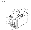
- Figure 1 is an oblique external view of a counter which is a preferred embodiment of the control device of the invention.
- Figure 2 is an oblique external view of a counter which is a preferred embodiment of the control device of the invention.
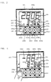
- Figure 2 is a frontal view of the same counter illustrating the normal counter operating mode.
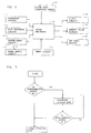
- Figure 3 is a block diagram showing the configuration of the essential components of the same counter.
- Figure 4 is a block diagram showing the configuration of the essential components of the same counter.
- Figure 4 is a frontal view of the same counter illustrating the dipswitch display mode.
- Figure 5 is a frontal view of the same counter illustrating the dipswitch display mode.
- Figure 5 is a flowchart illustrating the procedure followed by the same counter when switching between modes.
- Figure 6 is a flowchart illustrating the procedure followed by the same counter when switching between modes.
- Figure 6 is a frontal view of a timer which is another preferred embodiment of the control device of this invention, illustrating the mode for setting the one-shot output time.
- Figure 7 is a flowchart illustrating the procedure followed by the same timer when switching between modes.
- Figure 8 is an overhead view of an existing counter showing how it is mounted to its control panel.
- control device is a counter, however, the present invention is directed to control devices in general and is not limited to a counter.
- the counter includes a front assembly 101a, a base , a front panel 103, upper and lower panels 104 and 105, and left and right panels defining the printed circuit board assembly, as shown in Figs. 1 and 2.
- the counter includes a key panel 102 for setting numerical values provided on the front 101a of case 101.
- the keys 103A through 103D, as shown in Fig. 2, correspond to the four places in the numerical values to be set.
- Display 104 is the current value (current numerical value) display on the front 101a of the case 101. It can, for example, be made of seven-segment LEDs. Below the current value numeric display 104 on the front 101a of case 101 is a four-place set value numeric display 105, which may also be made from seven-segment LEDs.
- mode switch assembly 107 On the face 101a is reset switch 106 with reset key 106a.
- mode switch assembly 107 Built into the interior of the case 101 and protected by cover C is mode switch assembly 107. This assembly may consist, for example, of eight dipswitches 108. When the key 108a of each dipswitch 108 is moved in direction a shown by the arrow, the input is switched on; when it is moved in direction b , the input is switched off.
- Fig. 2 is a frontal view of the face 101a of the case 101.
- the current value numeric display 104 shows "2806", while the set value display 105 shows "3462".
- the keyswitches 103A through 103D have up-counting keys 103a through 103d and down-counting keys 103a1 through 103d1. The four pairs of keys correspond to the four places in displays 104 and 105.
- reset display 109 On the face 101a of the case 101 is reset display 109, which lights up to display the state of the reset input entered via reset switch 106.
- reset key 106a When reset key 106a is operated, contact is made or broken in switch 106. The state of this input is shown when reset display 109 lights up.
- the output display 110 adjacent to reset display 109 on face 101a of the case 101, lights up to display the output state of the output circuit. If key protectors are installed on the switches 103A through 103D to prevent the values which have been set from being changed, a key protection display 111 is provided. This display lights up to show the input state of the key protectors.
- Fig. 3 is a block diagram showing the essential components of a counter designed as discussed above.
- the keyswitch circuit 112 is connected to the switches 103A through 103D and to reset switch 106.
- the mode switching circuit 113 switches the mode, and contains the dipswitches 108.
- microprocessor 114 the control circuit for input and output, mode switching circuit 113 switches the input mode of circuit 115, the circuit for input of numerical values, and the output mode of output circuit 116, which controls other devices and maximum counting speed and the one-shot output time.
- the system reset circuit is indicated as 117.
- the reset When the reset is pushed after the power from power supply circuit 118 has been applied, the system will return to ordinary counter operating mode, as shown in Fig. 2 . If, on the other hand, reset key 106a is pushed before the power from circuit 118 is applied, reset switch 106 will enter the ON state.
- the ON or OFF state of each dipswitch 108 in mode switch assembly 107 When power is applied to circuit 118, the ON or OFF state of each dipswitch 108 in mode switch assembly 107 will be displayed via current value display 104 and the set value display 105 as either a character 8 or a dash, as shown in Fig. 4.
- a character 8 indicates that the input of the corresponding dipswitch 108 is on; a dash indicates that it is off. If the dipswitch 108 consist of eight switches arrayed in direction c-d indicated by an arrow, then the on-off state of switches #1 through #4 can be shown on segments #4a through #4d of current value numeric display 104, and the on-off state of switches #5 through #8 can be shown on segments #5a through #5d of set value display 105.
- the counter shown in Fig. 4 is set to dipswitch display mode. From this display, the operator can verify that switches #2, #3, #5, #6 and #8 are on, while switches 1, 4 and 7 are off.
- the microprocessor 14 controls the input and output by synchronizing them with clock pulses generated by circuit 119.
- the on-off state of reset switch 106 and the on-off states of the eight dipswitches 108 in mode switch assembly 107 are also stored in the microprocessor 114.
- the microprocessor 114 distinguishes whether or not there is pressure on reset key 106a, that is, whether switch 106 is on or off (Step 20: Judgment). If the key 106a is not depressed, counting will proceed in normal counter operating mode; the number "2806" will appear on current value display 104; and the number "3462” will appear on set value display 105 (Step 21: Processing). When the aforesaid numerical value reaches the set value, 3462, circuit 116 will output an ON signal.
- Step 20 If reset key 106a is held down so that reset switch 106 is on when power is applied to the circuit 118, the judgment will be made in Step 20 that key 106a has been pressed, and the on-off states of dipswitches #1 through #8 will be displayed on segments 104a through 104d of current value display 104 and 105a through 105d of set value display 105, as shown in Fig. 14 (Step 22: Processing). An "8" will be displayed if the input of that dipswitch is on, and a dash will be displayed if it is off.
- dipswitches 108 consist of eight switches arrayed in direction c-d indicated by an arrow in Fig. 1, then the on-off state of switches #1 through #4 will be shown on segments 104a through 104d of current value display 104, and the on-off state of switches #5 through #8 will be shown on segments 105a through 105d of set value display 105.
- the counter shown in Fig. 4 is set to dipswitch display mode. From this display, the operator can verify that switches #2, #3, #5, #6 and #8 are on, while switches #1, #4 and #7 are off. The entire process of verification is extremely simple.
- control device is a timer. Since the external appearance of this timer is virtually identical to that shown in Fig. 1 and its essential components are virtually identical to those shown in Fig. 3, further diagrams and discussion of these common aspects have been omitted.
- the timer of this embodiment does have aspects in which it differs from the preceding embodiment.
- the primary values appearing on current value display 104 and set value display 105 will be current time and set time.
- Mode switching circuit 113 in Fig. 3 switches the mode of circuit 115, which is used to input numerical values; the mode of circuit 116, which controls other devices; maximum counting speed; and input filter time.
- the auxiliary value which can be set or changed is the one-shot output time, which will be discussed below.
- a predetermined up and down-counting keys 103a through 103d and 103a1 through 103d1 were pressed to turn on certain of the four switches 103A through 103D, which constitute the main input switches.
- switches 103A and 103B were turned on when the operator pressed down-counting keys 103a1 and 103b1 before power was applied to circuit 118.
- the device shifts into the mode for setting the one-shot output time.
- the value for the one-shot output time which is currently set, in this case "1.00sec" will appear in set value display 105 as shown in Fig. 6.
- current value display 104 When the timer is in the mode for setting the one-shot output time, as discussed above, current value display 104 will be off so that the operator can distinguish clearly by eye the display used for this mode from that used for normal mode or other modes.
- the user selects a value by manipulating as the user chooses the up keys 103a through 103d and the down keys 103a1 through 103d1 to set the four switches 103A through 103D.
- the value for the one-shot output time which the user has set appears on the set value display 105 in real time.
- the one-shot output time can be set anywhere in the range between 0.01 sec. and 99.99 sec. If the value is set to 0.00 sec., the output will be held, and will normally remain on from the time of output until it is reset.
- the one-shot output time which has been set or changed will be written into and stored in the system memory (e.g. an EEPROM, not pictured) when the power supply is cut off.
- the control output is off; timing cannot be performed; START and RESET commands cannot be input; and the reset key cannot be operated.
- the on-off state of reset switch 106 and the on-off states of the eight dipswitches 108 in mode switch assembly 107 are also stored in the microprocessor 114.
- the microprocessor 114 distinguishes whether or not there is pressure on keys 106a, 103a through 103d and 103a1 through 103d1 (Steps 30-32: Judgments). If keys 106a, 103a, 103b, 103a1 and 103b1 are not depressed, the timer will be in normal operating mode, timing will be performed, and the current value and the set time will appear on current value display 104 and set value display 105 (Step 33: Processing). In normal operating mode, when the timing value and the set time coincide, circuit 116 will output an ON signal.
- any of the keys 106a, 103a, 103b, 103a1 and 103b1 have been pressed, which combination of keys has been pressed will be determined when power is applied to circuit 118. If only down keys 103a1 and 103b1 are on, the timer will shift into the mode for setting the one-shot output time. If only reset key 106a and up keys 103a and 103b are on, the timer will shift into the hardware testing mode. If only reset key 106a is on, it will shift into the dipswitch display mode.
- Dipswitch display mode remains in effect only as long as reset key 106a is depressed. When key 106a is released, this mode goes off, and the timer reverts to normal operating mode. For all other modes, the mode will be selected based on the judgment made at the time power is applied, and the timer will remain in the selected mode as long as power continues to be applied to circuit 118.
- values are set just as in normal setting mode.
- the operator selects a value by manipulating as he chooses the up keys 103a through 103d and the down keys 103a1 through 103d1 to set the four aforementioned rotary switches 103A through 103D.
- the value for the one-shot output time which he has set appears on the aforesaid set value display 105 in real time.
- the one-shot output time which has been changed as described above will be stored in the system memory.
- thermoregulator In the preferred embodiments discussed above, this invention was applied to a counter and a timer. It would, of course, also be possible for a control device designed according to this invention to be a thermoregulator or other control device.
- the control device described above shows on the aforesaid display the on-off state of each dipswitch when the appropriate switch is held down while power is being applied. This display stays on as long as the switch is depressed. This enables the operator to easily verify the state of the dipswitches by viewing the front of the case regardless of whether the case is mounted on the control panel. Thus, it significantly reduces the labor required to verify the state of the switches.
- the control device may be distinguished by the fact that when a predetermined key, which is one of the operating keys of the main input switch assembly, is held down while the power supply is being connected, the device shifts into auxiliary setting mode and the current auxiliary values are displayed on the main numeric display.
- the auxiliary values can be set or changed easily, and no special switches are needed. There is no mode key, so the user cannot accidentally change the values, nor can they be changed as a joke or prank. Since one set of operating keys on the front of the case is used to set both the main and the auxiliary values, the size of the keytops can be increased to make it easier for the user to operate the switches. Using the operating keys to change the auxiliary values allows greater accuracy and precision than do dipswitches or a continuously variable switch.
Landscapes
- Physics & Mathematics (AREA)
- General Physics & Mathematics (AREA)
- Engineering & Computer Science (AREA)
- Automation & Control Theory (AREA)
- Microelectronics & Electronic Packaging (AREA)
- Electric Clocks (AREA)
- Feedback Control In General (AREA)
Claims (7)
- Steuervorrichtung zum Steuern elektronischer Geräte mit einer Anzeige, umfassend:worin die Steuerschaltung (114) betätigt werden kann, um den EIN/AUS-Modus der internen manuellen Schalter (108) anzuzeigen.eine Steuerschaltung (114);eine Modus-Umschalt-Anordnung zum Umschalten zwischen Betriebsmodi, wobei die Anordnung eine Anzahl interner manueller Schalter (108) umfasst, die an die Steuerschaltung (114) angeschlossen sind; undeine Anzeigenanordnung (101a), die eine Vielzahl von Tastschaltern (102) umfasst, die elektronisch an die Steuerschaltung (114) angeschlossen sind,
- Vorrichtung nach Anspruch 1, worin zumindest ein vorbestimmter Tastschalter (106a), wenn er unmittelbar vor dem Zuführen von Strom zur Vorrichtung betätigt wird, die Anzeige des EIN- oder AUS-Status eines jeden internen manuellen Schalter (108) in Gang setzt.
- Vorrichtung nach Anspruch 1, worin der manuelle interne Schalter (108) ein DIP-Schalter ist.
- Vorrichtung nach Anspruch 2, worin die Steuerschaltung (114) eine solche Konfiguration hat, dass sie den EIN- oder AUS-Status eines jeden internen manuellen Schalters (108) nur anzeigt, während der vorbestimmte Schalter (106a) niedergehalten wird und gedrückt bleibt.
- Vorrichtung nach Anspruch 1, worin zumindest ein vorbestimmter Tastschalter (103a1, 103b1), wenn er unmittelbar vor dem Zuführen von Strom zur Vorrichtung betätigt wird, bewirkt, dass sich die Schalteranordnung in ihren Hilfseinstellmodus umschaltet, wobei die aktuellen Hilfswerte auf einer nummerischen Hauptanzeige (105) angezeigt werden, wobei die Hilfswerte durch nachfolgendes Betätigen der Tastschalter (102) im Hilfsmodus geändert werden können.
- Vorrichtung nach Anspruch 5, worin die Hilfswerte eine Einschaltdauer eines monostabilen Ausgangssignals für die Vorrichtung darstellen.
- Vorrichtung nach Anspruch 5, worin eine Einschaltdauer, die eingestellt worden ist, im Systemspeicher gespeichert wird, wenn der Strom abgeschaltet wird.
Applications Claiming Priority (10)
| Application Number | Priority Date | Filing Date | Title |
|---|---|---|---|
| JP35784392 | 1992-12-25 | ||
| JP35784392A JP3358092B2 (ja) | 1992-12-25 | 1992-12-25 | 制御機器のフロントケース構造 |
| JP357843/92 | 1992-12-25 | ||
| JP42071/93 | 1993-02-04 | ||
| JP4207193 | 1993-02-04 | ||
| JP4207193 | 1993-02-04 | ||
| JP5284501A JPH06289926A (ja) | 1993-02-04 | 1993-10-18 | 制御機器 |
| JP28450193 | 1993-10-18 | ||
| JP284501/93 | 1993-10-18 | ||
| EP93310247A EP0604138B1 (de) | 1992-12-25 | 1993-12-17 | Steuervorrichtung |
Related Parent Applications (2)
| Application Number | Title | Priority Date | Filing Date |
|---|---|---|---|
| EP93310247.7 Division | 1993-12-17 | ||
| EP93310247A Division EP0604138B1 (de) | 1992-12-25 | 1993-12-17 | Steuervorrichtung |
Publications (3)
| Publication Number | Publication Date |
|---|---|
| EP0716564A2 EP0716564A2 (de) | 1996-06-12 |
| EP0716564A3 EP0716564A3 (de) | 1997-03-26 |
| EP0716564B1 true EP0716564B1 (de) | 2000-06-28 |
Family
ID=27291057
Family Applications (2)
| Application Number | Title | Priority Date | Filing Date |
|---|---|---|---|
| EP93310247A Expired - Lifetime EP0604138B1 (de) | 1992-12-25 | 1993-12-17 | Steuervorrichtung |
| EP96103775A Expired - Lifetime EP0716564B1 (de) | 1992-12-25 | 1993-12-17 | Steuergerät |
Family Applications Before (1)
| Application Number | Title | Priority Date | Filing Date |
|---|---|---|---|
| EP93310247A Expired - Lifetime EP0604138B1 (de) | 1992-12-25 | 1993-12-17 | Steuervorrichtung |
Country Status (3)
| Country | Link |
|---|---|
| US (2) | US5631673A (de) |
| EP (2) | EP0604138B1 (de) |
| DE (2) | DE69328938T2 (de) |
Families Citing this family (17)
| Publication number | Priority date | Publication date | Assignee | Title |
|---|---|---|---|---|
| US7171461B2 (en) * | 1996-07-23 | 2007-01-30 | Server Technology, Inc. | Network remote power management outlet strip |
| US5737039A (en) * | 1996-08-13 | 1998-04-07 | Sony Corporation | Control panel for a television |
| DE19717909C2 (de) * | 1997-04-24 | 2001-07-05 | Siemens Ag | Elektrisches Gerät |
| FR2775865B1 (fr) * | 1998-03-04 | 2000-06-09 | Valeo Electronique | Tableau de commande a circuit imprime, en particulier pour vehicule automobile |
| TW476231B (en) * | 1998-11-30 | 2002-02-11 | Omron Tateisi Electronics Co | Electronic machine |
| US6791041B1 (en) * | 2003-03-27 | 2004-09-14 | Kuo-Sheng Chen | IA switch |
| US8463315B2 (en) * | 2004-06-21 | 2013-06-11 | Research In Motion Limited | Handheld wireless communication device |
| US8537117B2 (en) * | 2006-02-13 | 2013-09-17 | Blackberry Limited | Handheld wireless communication device that selectively generates a menu in response to received commands |
| US7770118B2 (en) * | 2006-02-13 | 2010-08-03 | Research In Motion Limited | Navigation tool with audible feedback on a handheld communication device having a full alphabetic keyboard |
| US8000741B2 (en) * | 2006-02-13 | 2011-08-16 | Research In Motion Limited | Handheld wireless communication device with chamfer keys |
| TWI330278B (en) * | 2006-09-01 | 2010-09-11 | Chimei Innolux Corp | Liquid crystal display device |
| CN201995255U (zh) * | 2010-11-30 | 2011-09-28 | 欧姆龙株式会社 | 控制装置 |
| DE102013106578A1 (de) * | 2013-06-24 | 2014-12-24 | Endress + Hauser Flowtec Ag | Feldgerät |
| ITUA20163673A1 (it) * | 2016-05-23 | 2017-11-23 | Hike S R L | Apparecchio elettrico di controllo, particolarmente per sistemi domotici. |
| USD904312S1 (en) * | 2018-07-04 | 2020-12-08 | Omron Corporation | Signal transfer connector |
| DE102019208213A1 (de) * | 2019-06-05 | 2020-12-10 | Siemens Aktiengesellschaft | Elektrisches Gerät |
| CN219806660U (zh) * | 2023-05-10 | 2023-10-10 | 金玲华 | 一种字母及数字装饰板 |
Family Cites Families (12)
| Publication number | Priority date | Publication date | Assignee | Title |
|---|---|---|---|---|
| US4295180A (en) * | 1980-06-04 | 1981-10-13 | Herron Clifford W | Wall mountable housing for programmable thermostat |
| US4488148A (en) * | 1982-02-19 | 1984-12-11 | Becton, Dickinson And Company | Combination switching and display electronic modular control unit |
| JPS58171217A (ja) * | 1982-04-02 | 1983-10-07 | Inoue Japax Res Inc | 放電加工装置の加工条件選択設定装置 |
| US4896370A (en) * | 1987-03-27 | 1990-01-23 | Teletec Corporation | Control system for microprocessor and software enhanced communications equipment |
| JP2506990B2 (ja) * | 1988-09-22 | 1996-06-12 | 松下電器産業株式会社 | 電子機器の表示装置 |
| US4902878A (en) * | 1988-11-04 | 1990-02-20 | General Electric Company | Data entry and control arrangement for an appliance |
| JPH02304589A (ja) * | 1989-05-19 | 1990-12-18 | Matsushita Electric Ind Co Ltd | 液晶表示装置 |
| JP3219761B2 (ja) * | 1990-11-19 | 2001-10-15 | ソニー株式会社 | リモートコマンダー |
| JPH04196727A (ja) * | 1990-11-27 | 1992-07-16 | Matsushita Electric Ind Co Ltd | 小型電子機器用表示装置 |
| DE9017103U1 (de) * | 1990-12-19 | 1991-03-07 | Mannesmann Kienzle Gmbh, 78052 Villingen-Schwenningen | Anordnung zum Verbinden zweier Gehäuseteile eines Einbaugehäuses |
| US5160832A (en) * | 1991-05-17 | 1992-11-03 | Best Power Technology, Inc. | Front panel unit for electronic equipment |
| US5398597A (en) * | 1993-09-24 | 1995-03-21 | Henny Penny Corporation | Electronic control system for cooking system |
-
1993
- 1993-12-17 DE DE69328938T patent/DE69328938T2/de not_active Expired - Fee Related
- 1993-12-17 EP EP93310247A patent/EP0604138B1/de not_active Expired - Lifetime
- 1993-12-17 EP EP96103775A patent/EP0716564B1/de not_active Expired - Lifetime
- 1993-12-17 DE DE69322368T patent/DE69322368T2/de not_active Expired - Fee Related
- 1993-12-20 US US08/169,137 patent/US5631673A/en not_active Expired - Fee Related
-
1997
- 1997-05-20 US US08/859,260 patent/US6014152A/en not_active Expired - Fee Related
Also Published As
| Publication number | Publication date |
|---|---|
| DE69328938D1 (de) | 2000-08-03 |
| US6014152A (en) | 2000-01-11 |
| DE69322368D1 (de) | 1999-01-14 |
| EP0604138B1 (de) | 1998-12-02 |
| DE69328938T2 (de) | 2000-11-30 |
| EP0716564A2 (de) | 1996-06-12 |
| EP0604138A1 (de) | 1994-06-29 |
| US5631673A (en) | 1997-05-20 |
| DE69322368T2 (de) | 1999-06-02 |
| EP0716564A3 (de) | 1997-03-26 |
Similar Documents
| Publication | Publication Date | Title |
|---|---|---|
| US6014152A (en) | Control device | |
| AU630081B2 (en) | Programmable control system | |
| US5969718A (en) | Method and apparatus for providing a softkey prompted user interface | |
| JPH02103114A (ja) | 射出成形機の成形条件設定方法 | |
| JPH0791719A (ja) | 空気調和装置の集中コントローラー及び空気調和装置の伝送アドレスの設定方法及び空気調和装置のインターフェース装置 | |
| EP0756218B1 (de) | Miniaturbedienungspult für Drucker | |
| US4831226A (en) | Control system with hidden reprogramming switch | |
| US5544959A (en) | Removable keypad for an electronic circuit breaker | |
| GB2054471A (en) | A freely assignable keyboard | |
| US20030174073A1 (en) | Keypad indicating arrangement including virtual key | |
| KR100327993B1 (ko) | 제어 장치 | |
| EP0143045B1 (de) | Schaltung zur Auswahl und Verriegelung eines Betriebsfunktionsschaltkreises | |
| JP2853128B2 (ja) | 制御用電子機器 | |
| JPH05111578A (ja) | 4個のビデオゲームボードを有するスイツチングおよび制御システム | |
| US4447798A (en) | Processor select switch | |
| KR100888944B1 (ko) | 프로그램가능한 로직 콘트롤러용 스위치 장치 | |
| JPH06289926A (ja) | 制御機器 | |
| JP2714545B2 (ja) | 電気錠 | |
| KR200286283Y1 (ko) | 제어기기의 파라미터 잠금장치 | |
| JPH0916215A (ja) | プログラマブル表示器 | |
| US4340945A (en) | Operating apparatus for an appliance of a motor vehicle | |
| EP1211703B1 (de) | Fernbedieneinheit für elektronische Geräte | |
| US5317906A (en) | Refrigerant configuration system | |
| KR100189925B1 (ko) | 복합 제품에서의 모드 변환 선택 에러 표시 방법 | |
| SU1275416A1 (ru) | Устройство дл ввода-вывода информации |
Legal Events
| Date | Code | Title | Description |
|---|---|---|---|
| PUAI | Public reference made under article 153(3) epc to a published international application that has entered the european phase |
Free format text: ORIGINAL CODE: 0009012 |
|
| AC | Divisional application: reference to earlier application |
Ref document number: 604138 Country of ref document: EP |
|
| AK | Designated contracting states |
Kind code of ref document: A2 Designated state(s): DE FR GB IT |
|
| PUAL | Search report despatched |
Free format text: ORIGINAL CODE: 0009013 |
|
| AK | Designated contracting states |
Kind code of ref document: A3 Designated state(s): DE FR GB IT |
|
| 17P | Request for examination filed |
Effective date: 19970925 |
|
| 17Q | First examination report despatched |
Effective date: 19990108 |
|
| GRAG | Despatch of communication of intention to grant |
Free format text: ORIGINAL CODE: EPIDOS AGRA |
|
| 17Q | First examination report despatched |
Effective date: 19990108 |
|
| GRAG | Despatch of communication of intention to grant |
Free format text: ORIGINAL CODE: EPIDOS AGRA |
|
| GRAH | Despatch of communication of intention to grant a patent |
Free format text: ORIGINAL CODE: EPIDOS IGRA |
|
| GRAH | Despatch of communication of intention to grant a patent |
Free format text: ORIGINAL CODE: EPIDOS IGRA |
|
| GRAA | (expected) grant |
Free format text: ORIGINAL CODE: 0009210 |
|
| AC | Divisional application: reference to earlier application |
Ref document number: 604138 Country of ref document: EP |
|
| AK | Designated contracting states |
Kind code of ref document: B1 Designated state(s): DE FR GB IT |
|
| REF | Corresponds to: |
Ref document number: 69328938 Country of ref document: DE Date of ref document: 20000803 |
|
| ITF | It: translation for a ep patent filed | ||
| ET | Fr: translation filed | ||
| PLBE | No opposition filed within time limit |
Free format text: ORIGINAL CODE: 0009261 |
|
| STAA | Information on the status of an ep patent application or granted ep patent |
Free format text: STATUS: NO OPPOSITION FILED WITHIN TIME LIMIT |
|
| 26N | No opposition filed | ||
| REG | Reference to a national code |
Ref country code: GB Ref legal event code: IF02 |
|
| PGFP | Annual fee paid to national office [announced via postgrant information from national office to epo] |
Ref country code: FR Payment date: 20041208 Year of fee payment: 12 |
|
| PGFP | Annual fee paid to national office [announced via postgrant information from national office to epo] |
Ref country code: DE Payment date: 20041209 Year of fee payment: 12 |
|
| PGFP | Annual fee paid to national office [announced via postgrant information from national office to epo] |
Ref country code: GB Payment date: 20041215 Year of fee payment: 12 |
|
| PG25 | Lapsed in a contracting state [announced via postgrant information from national office to epo] |
Ref country code: IT Free format text: LAPSE BECAUSE OF NON-PAYMENT OF DUE FEES;WARNING: LAPSES OF ITALIAN PATENTS WITH EFFECTIVE DATE BEFORE 2007 MAY HAVE OCCURRED AT ANY TIME BEFORE 2007. THE CORRECT EFFECTIVE DATE MAY BE DIFFERENT FROM THE ONE RECORDED. Effective date: 20051217 Ref country code: GB Free format text: LAPSE BECAUSE OF NON-PAYMENT OF DUE FEES Effective date: 20051217 |
|
| PG25 | Lapsed in a contracting state [announced via postgrant information from national office to epo] |
Ref country code: DE Free format text: LAPSE BECAUSE OF NON-PAYMENT OF DUE FEES Effective date: 20060701 |
|
| GBPC | Gb: european patent ceased through non-payment of renewal fee |
Effective date: 20051217 |
|
| PG25 | Lapsed in a contracting state [announced via postgrant information from national office to epo] |
Ref country code: FR Free format text: LAPSE BECAUSE OF NON-PAYMENT OF DUE FEES Effective date: 20060831 |
|
| REG | Reference to a national code |
Ref country code: FR Ref legal event code: ST Effective date: 20060831 |