EP0716833A2 - Methode und Gerät zur Dichtung einer Stelle im Körper - Google Patents
Methode und Gerät zur Dichtung einer Stelle im Körper Download PDFInfo
- Publication number
- EP0716833A2 EP0716833A2 EP95308976A EP95308976A EP0716833A2 EP 0716833 A2 EP0716833 A2 EP 0716833A2 EP 95308976 A EP95308976 A EP 95308976A EP 95308976 A EP95308976 A EP 95308976A EP 0716833 A2 EP0716833 A2 EP 0716833A2
- Authority
- EP
- European Patent Office
- Prior art keywords
- sealant
- puncture
- outlet
- stopping means
- sealing
- Prior art date
- Legal status (The legal status is an assumption and is not a legal conclusion. Google has not performed a legal analysis and makes no representation as to the accuracy of the status listed.)
- Withdrawn
Links
Images


Classifications
-
- A—HUMAN NECESSITIES
- A61—MEDICAL OR VETERINARY SCIENCE; HYGIENE
- A61B—DIAGNOSIS; SURGERY; IDENTIFICATION
- A61B17/00—Surgical instruments, devices or methods
- A61B17/0057—Implements for plugging an opening in the wall of a hollow or tubular organ, e.g. for sealing a vessel puncture or closing a cardiac septal defect
-
- A—HUMAN NECESSITIES
- A61—MEDICAL OR VETERINARY SCIENCE; HYGIENE
- A61B—DIAGNOSIS; SURGERY; IDENTIFICATION
- A61B17/00—Surgical instruments, devices or methods
- A61B17/00491—Surgical glue applicators
-
- A—HUMAN NECESSITIES
- A61—MEDICAL OR VETERINARY SCIENCE; HYGIENE
- A61B—DIAGNOSIS; SURGERY; IDENTIFICATION
- A61B17/00—Surgical instruments, devices or methods
- A61B17/0057—Implements for plugging an opening in the wall of a hollow or tubular organ, e.g. for sealing a vessel puncture or closing a cardiac septal defect
- A61B2017/00637—Implements for plugging an opening in the wall of a hollow or tubular organ, e.g. for sealing a vessel puncture or closing a cardiac septal defect for sealing trocar wounds through abdominal wall
-
- A—HUMAN NECESSITIES
- A61—MEDICAL OR VETERINARY SCIENCE; HYGIENE
- A61B—DIAGNOSIS; SURGERY; IDENTIFICATION
- A61B17/00—Surgical instruments, devices or methods
- A61B17/0057—Implements for plugging an opening in the wall of a hollow or tubular organ, e.g. for sealing a vessel puncture or closing a cardiac septal defect
- A61B2017/00646—Type of implements
- A61B2017/0065—Type of implements the implement being an adhesive
Definitions
- the present invention relates to method and apparatus for sealing, including for use in sealing an arterial puncture produced, for example, by an arterial catheterization procedure.
- the catheter Upon termination of a catheterization process where the catheter is removed from, for example, an artery, the artery puncture caused by the catheter must be properly closed to prevent bleeding complications. For example, such bleeding complications lead to the formation of a hematoma which, in turn, can necessitate surgery.
- hemostatic devices for sealing such arterial punctures require lengthy procedures (e.g., 20-40 minutes) and/or are uncomfortable for the patient (e.g., cauterization of the puncture). Further, such devices may require accurately positioning a patch on the puncture or a plug into the puncture. Inaccurate positioning may lead to bleeding from the puncture, occlusion of blood flow in the artery and/or a portion of the patch or plug dislodging into the artery.
- the present invention relates to a method and apparatus for sealing to control bleeding or other body fluid flow in conjunction with a medical procedure including the patching of a puncture in a body lumen, such as an artery having a puncture to be sealed after the removal of an arterial catheter.
- the present invention is directed to a hemostatic apparatus which enters a tissue opening providing access to such a puncture and seals the puncture by injecting a gelatinous bioabsorptive sealant, having the property of being tissue adhesive, into tissue adjacent to the lumen puncture.
- the sealant is prevented from entering the lumen by providing a covering or barrier for the lumen puncture while the sealant is being positioned about the puncture.
- the sealant is delivered from the apparatus at a predetermined distance from the puncture.
- the capability is provided to indicate when the apparatus is properly located in preparation for sealant injection. More precisely, a guide thread or wire is used with the apparatus. When an end of the wire has been threaded into the lumen puncture, then an opposite end can be inserted through a guide bore traversing a longitudinal axis of the apparatus. This provides a way to guide the apparatus to the lumen puncture. That is, an insertion tip of the apparatus is guided into the lumen puncture until an insertion stop provides resistance to further entry into the puncture, thereby indicating to a health care giver using the apparatus that it is properly positioned.
- the sealant used is a composition that includes thrombin and fibrinogen and is formed, immediately prior to injection, from a mixing of the components. Note that this sealant can form an effective arterial patch in less than five minutes and typically less than two minutes.
- the practitioner or health care giver need only apply manual external pressure during the use of the apparatus and for a minimal amount of time thereafter (e.g., less than two minutes) while allowing the sealant to firmly adhere to the tissue adjacent to the puncture.
- this pressure is provided by the practitioner directly by using his/her fingers against the skin adjacent to the puncture.
- a pressure applicator device engages the patient's skin and a force is applied to the skin by the device.
- the pressure applicator device is also able to forcefully engage the patient's skin after removal of the apparatus that delivers the sealant.
- An additional embodiment of the present invention utilizes an inflatable balloon as an insertion stop. Instead of being located outside of a body vessel, it is positioned inwardly of the vessel wall. After being so positioned through the puncture of the vessel wall, the balloon is inflated and the sealant is delivered at the puncture. The balloon blocks the vessel puncture and prevents the sealant from entering the vessel puncture.
- the sealant is delivered without the use of an insertion stop.
- the apparatus is inserted through an incision or puncture in the skin tissue. After being positioned in the proper location like a fatty area, such as a breast, the sealant is delivered through apertures formed adjacent to the distal end of the apparatus.
- This particular apparatus has utility for controlling body fluid discharge and for plugging or otherwise filling cavities that result from a medical procedure, such as involving a tissue biopsy.
- a medical apparatus for delivery of a sealant to control body fluid and/or serve as a filler for a body cavity created as a result of a tissue biopsy.
- the apparatus can be readily manipulated for delivering the sealant to the desired location. Patches that are difficult to manipulate are not needed.
- Necessary pressure for controlling the positioning and maintaining of the sealant is readily accomplishable by directly using fingers of the practitioner or, alternatively, using a pressure applicator device that is able to forcefully engage the skin tissue adjacent to the body area of interest.
- the sealant that is utilized can be a single component or is, preferably, a composition that includes thrombin and fibrinogen. The apparatus is able to provide a desired mixing of these two components.
- Fig. 1 provides a perspective view of the hemostatic apparatus 20 of the present invention. Proceeding from the apparatus end 24, which remains external to the patient's body, an apparatus trunk 28 is provided which constitutes the majority of the length of the apparatus 20.
- the trunk 28 provides a sealant input channel 32 for inputting a hemostatic sealant 34 via tubing 38.
- the sealant 34 may be created from two components, which require mixing in a mixing chamber 96 prior to injection.
- trunk 28 provides at least one interior chamber (discussed below) for conveying the hemostatic sealant 34 from the sealant input channel 32 to one or more sealant dispensing apertures 36 which are located internal to the patient when the sealant 34 exits the apertures for sealing an arterial puncture.
- the trunk 28 can be defined as including (a) an upper section 40 having the sealant input channel 32 and (b) a lower section 48 having the sealant dispensing apertures.
- the upper section 40 is preferably formed as a single piece of rigid material, such as a rigid plastic, for ease of manipulation of apparatus 20 by a medical practitioner.
- the lower section 48 is fused or glued to the upper section 40 at seam 52, the lower section 48 being substantially cylindrical.
- the lower section 48 preferably consists of a flexible material such as polyvinyl chloride. Such flexibility is advantageous in the lower section 48 since, when the apparatus 20 is positioned within a patient (e.g., Fig. 5), the end of lower section 48 having apertures 36 is internal to the patient while the opposing seam 52, remains external to the patient. This flexibility facilitates use by the practitioner and affords greater comfort for the patient when the apparatus 20 is used.
- a stem 56 having three geometrically distinct segments along its length traversing from apertures 36 to stem end 60.
- the segments are, respectively, an insertion tip 64 for entering an arterial puncture; an insertion stop 68 having larger diameter than the puncture such that only the insertion tip 64 is able to enter the artery or lumen to be patched; and a spacing tube 72 which provides the remainder of the spacing, preferred for the present invention, between the insertion tip 64 and the apertures 36.
- the stem 56 is also preferably a single molded piece of flexible material and that the stem 56 and the lower portion 48 may be fused together as a single integrated unit.
- the distance between the apertures 36 and the distal end 74 of the insertion stop 68 should be between about 0.125 inch and 1 inch.
- a guide bore 76 Centrally located along the length of the device 20 is a guide bore 76.
- the guide bore 76 is used in conjunction with an arterial guide wire or thread 124 (as shown in, for example, Fig. 9) so that when the arterial guide wire is threaded through the guide bore 76 from the stem end 60, the apparatus 20, and more particularly the insertion tip 64, can be reliably guided into the arterial puncture to be sealed.
- the trunk 28 includes one or more sealant delivery chambers 80 which deliver the hemostatic sealant 34 from the sealant input channel 32 to the apertures 36 which are best illustrated in Fig. 4.
- each such sealant delivery chamber 80 has an upper end area 84 open to the internal bore 88 of the sealant input channel 32.
- each sealant delivery chamber 80 is also open to an aperture 36 for injecting the sealant 34 into the patient.
- partition 92 entirely separates the sealant delivery chambers 80 from the guide bore 76 (Fig. 3).
- the partition 92 is tubular in shape and its lower end, adjacent apertures 36, may be integrally formed with stem 56 such that spacing tube 72 can be considered an extension of the partition 92.
- the sealant 34 may be composed of two or more components which require mixing immediately prior to use.
- the mixing chamber 96 is used to mix the two sealant components contained in tubes 100 and 104, respectively.
- one of the two components (contained in one of the tubes 100 or 104) include thrombin and the other component (contained in the other tube 100 or 104) include fibrinogen.
- the pre-prepared sealant may be injected into the tubing 38 from a single conventional syringe, thus precluding the need for a mixing chamber 96.
- Fig. 6 shows an arterial catheter or introducer 108 which is tubular in nature having an open end 116 internal to the artery 112 and an opposite open end 120 external to the patient, thereby maintaining access to the artery blood flow from outside the patient.
- an arterial guide wire is introduced into the catheter 108, as shown in Fig. 7.
- the introducer 108 is removed from the patient and, as shown in Fig. 9, the arterial guide wire 124 is threaded through the guide bore 76 of device 20. Subsequently, in Fig.
- apparatus 20 is guided through the catheter opening where the introducer 108 previously resided until the insertion tip 64 enters the artery 112 through the arterial puncture and there is resistance to further entry due to the insertion stop 68 preventing the device 20 from proceeding further into the artery.
- the arterial guide wire 124 may be removed from the patient.
- the sealant 34 is urged from the apertures 36 in the general direction of the arterial puncture. Further note that manual pressure about the catheter opening may be initiated at this time as depicted by the dash fingertips in this figure.
- Fig. 12A as the sealant 34 exits the apparatus 20 it forms a substantially single viscous mass which is tissue adhesive. Also as depicted in this figure, pressure is applied on the external body site adjacent the catheter opening in order to facilitate the sealant's flow such that the sealant substantially completely surrounds the insertion stop 68. Following this step, as shown in Fig. 14, the apparatus 20 is removed from the patient.
- Figs. 11B and 12B depict steps analogous to the steps depicted in Figs. 11A and 12A, respectively, however, the guide wire 124 remains in place within the apparatus 20 while the sealant 34 is being injected into the patient.
- the guide wire 124 may subsequently be removed either before the apparatus 20 is removed, as in Fig. 13A, or alternatively the guide wire 124 can be removed concurrently with the apparatus 20, as depicted in Fig. 13B.
- the steps corresponding to Figs. 14 and 15 are performed.
- a pressure applicator device 150 forcefully engages the skin during the delivery of the sealant 34 adjacent to the body puncture.
- the pressure applicator device 150 includes a pressure applying member 154, that is frusto-conical in shape, and with an annular surface 156 for contacting the skin.
- a body member 160 Integral with the pressure applying member 154 is a body member 160 having a free end adjacent to which gripping wings 164a, 164b are attached or formed.
- a bore 168 (Fig. 17), which is of a diameter or size so that it can receive, and be positioned around, at least portions of the trunk 28 including the lower section 48.
- the pressure applying member 156 forcefully engages the skin using the force applied by the fingers of the medical practitioner to the wings 164a, 164b.
- the force applied is sufficient to influence the positioning of the sealant 34 at the desired location adjacent to the body puncture.
- the pressure applicator device 150 can be moved relative to the apparatus 20. That is, as illustrated in Fig. 16B, after the sealant 34 has been properly delivered to the puncture, the apparatus 20 is removed while the pressure applicator device 150 remains in place to continue to apply pressure for the relatively short, desired time period.
- a further embodiment of the invention for supplying a sealant to a body site having a puncture is described that may, but need not, include the pressure applicator device 150.
- the apparatus 180 of this further embodiment has a tubular sleeve 184 that is hollow to define a sealant conduit 188.
- balloon catheter 192 held within the sealant conduit 188 is balloon catheter 192 having a size or diameter less than that of the sealant conduit 188 to permit sealant to exit the outlet or aperture 196 at the free end of the tubular sleeve 184.
- the balloon catheter 192 has an insertion end 198 at a free end thereof that is insertable through a puncture at a body site.
- An inflatable balloon 200 (shown inflated in Fig. 17) is provided at a proximal end of the insertion end 198.
- the balloon 200 is inflated using holes 204 formed in the balloon catheter 192. Since the balloon holes 204 communicate with the balloon 200.
- the insertion end 198, together with the deflated balloon 200 are received through the wall of a body vessel, such as an artery.
- the balloon 200 is spaced from the outlet 196 by a desired distance, like in the apparatus 20.
- the desired distance between the outlet 196 and a proximal end 208 of the balloon 200 is comparable to the similar distance defined with respect to apparatus 20, i.e., in the range of .125 of an inch to 1 inch.
- a port 210 is provided for receiving a liquid substance, such as a sterile saline mixture.
- the port 210 communicates with a liquid passageway member 214, which is joined to the tubular sleeve 184.
- the outlet of the liquid passageway member 214 communicates with the balloon catheter 192.
- the apparatus 180 has a sealant delivery member 218 that is operatively joined to the tubular sleeve 184.
- the sealant 34 is comprised of the two components, thrombin and fibrinogen, which are introduced separately using a first sealant port 222 and a second sealant port 224.
- the two component sealant is mixed using the sealant delivery member 218.
- the sealant 34 is delivered for purposes of sealing or patching, it is caused to move or flow through the tubular conduit 188 and subsequently exits from the outlet 196.
- a puncture in a body site at a vascular graft, which is attached to a vein and an artery.
- a puncture may be the result of a medical dialysis procedure conducted using a patient's arm. After such a procedure, it is necessary to stop unwanted bleeding.
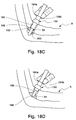
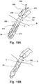
- an opterator O is in place and positioned through the skin tissue of the patient's arm A.
- the apparatus 180 is of a size to be inserted into and along the opterator O.
- the opterator O acts as a guide for the apparatus 180 so that it can be accurately positioned for use in delivering a sealant to control blood flow from the puncture.
- the opterator O is removed from the patient's arm A, as seen in Fig. 18B.
- the balloon 200 is supplied with the liquid and expands.
- the enlarged balloon 200 is located inwardly of the body vessel wall and prevents sealant from entering the body lumen.
- the sealant 34 is delivered and moves along the conduit 188 and exits the outlet 196. As illustrated in Fig. 18C, none of the sealant is able to pass into the body lumen.
- sealant 34 is escaping from the outlet 196, pressure is being applied to the outer skin adjacent to the puncture that is being patched.
- pressure is applied using the pressure applicator device 150. This assists in assuring that the sealant 34 is properly positioned for providing the desired patch in order to, for example, stop unwanted body vessel bleeding in the arm A.
- the apparatus 180 is removed from the arm A.
- the liquid in the balloon 200 of the balloon catheter 192 is removed so that the insertion end 196 can be removed past the vessel wall.
- the viscous sealant collapses or covers the space that was previously occupied by the balloon catheter 192, but does not pass into the body lumen.
- the pressure applicator device 150 is utilized to maintain pressure to influence the positioning of the sealant 34.
- the medical practitioner could have used his/her fingers pressed against the skin adjacent to the body site of interest.
- a stop or blocking member such as the insertion stop 68 or the balloon 200.
- an apparatus for supplying the sealant 34 to a body cavity.
- the body cavity C results from a medical procedure, such as a biopsy, that was performed on a patient. Such a biopsy may be performed, for example, in a patient's breast B. At the completion of the biopsy, body fluid tends to discharge and must be controlled, as well as filling the body cavity C.
- the apparatus 250 which includes a tubular sealant carrier 254 that can be defined as having a proximal section 258 and a distal section 262.
- the proximal section 258 communicates with first and second sealant ports 266, 270 that receive sealant components that are mixed together in the proximal section 258.
- first and second sealant ports 266, 270 that receive sealant components that are mixed together in the proximal section 258.
- single component sealants 34 can also be utilized.
- the distal section 262 has a length for extending into the body cavity C and is typically formed integral with the proximal section 258.
- the distal section 262 may be made of any length and the length thereof depends upon its particular application and/or the body make-up of the patient.
- the distal section 262 has a number of outlets or apertures 274 through which the sealant 34 passes for controlling body fluid discharge and/or filling the body cavity C.
- the distal section 262 is inserted into the body cavity C that resulted from the biopsy procedure.
- the sealant components are delivered through the first and second sealant ports 266, 270 into the sealant carrier 258.
- the sealant 34 moves from the proximal section 258 to the distal section 262 and exits the outlets 274 into the body cavity C.
- exterior pressure is applied to the skin, such as at the breast B outer wall.
- the pressure applicator device 150 is being used by the practitioner to provide the necessary force, although it should be appreciated that other means could be utilized, such as the fingers of the practitioner.
- the apparatus 250 is removed, while the pressure applicator device 150 remains in use. As the apparatus 250 is removed, the viscous sealant 34 occupies the space previously occupied by the proximal section 262. The medical practitioner continues to provide a force at the body cavity for the relatively short period of time while the sealant is curing or hardening.
- each apparatus can be made of appropriate materials and have varying sizes including, for example, the balloon 200 of the balloon catheter 192 being made of any suitable or proper inflatable material, such as a latex or a polyurethane material.
Landscapes
- Health & Medical Sciences (AREA)
- Surgery (AREA)
- Life Sciences & Earth Sciences (AREA)
- Biomedical Technology (AREA)
- Nuclear Medicine, Radiotherapy & Molecular Imaging (AREA)
- Engineering & Computer Science (AREA)
- Cardiology (AREA)
- Heart & Thoracic Surgery (AREA)
- Medical Informatics (AREA)
- Molecular Biology (AREA)
- Animal Behavior & Ethology (AREA)
- General Health & Medical Sciences (AREA)
- Public Health (AREA)
- Veterinary Medicine (AREA)
- Surgical Instruments (AREA)
Applications Claiming Priority (2)
| Application Number | Priority Date | Filing Date | Title |
|---|---|---|---|
| US35607394A | 1994-12-14 | 1994-12-14 | |
| US356073 | 1994-12-14 |
Publications (2)
| Publication Number | Publication Date |
|---|---|
| EP0716833A2 true EP0716833A2 (de) | 1996-06-19 |
| EP0716833A3 EP0716833A3 (de) | 1997-01-29 |
Family
ID=23400005
Family Applications (1)
| Application Number | Title | Priority Date | Filing Date |
|---|---|---|---|
| EP95308976A Withdrawn EP0716833A3 (de) | 1994-12-14 | 1995-12-11 | Methode und Gerät zur Dichtung einer Stelle im Körper |
Country Status (1)
| Country | Link |
|---|---|
| EP (1) | EP0716833A3 (de) |
Cited By (18)
| Publication number | Priority date | Publication date | Assignee | Title |
|---|---|---|---|---|
| EP0941697A1 (de) * | 1996-04-08 | 1999-09-15 | Tricardia, L.L.C. | Selbstschliessende vaskuläre Vorrichtung |
| EP1109498A4 (de) * | 1998-08-04 | 2003-01-08 | Fusion Medical Technologies | Perkutane gewebekanalverschlussvorrichtung und verfahren |
| WO2005063129A3 (en) * | 2003-12-24 | 2005-09-01 | Accessclosure Inc | Apparatus for delivering haemostatic sealing materials |
| WO2005082257A1 (ja) * | 2004-02-27 | 2005-09-09 | Waseda University | 医療用止血装置および止血方法 |
| US7441973B2 (en) | 2006-10-20 | 2008-10-28 | Ethicon Endo-Surgery, Inc. | Adhesive applicator |
| EP1478416A4 (de) * | 2001-11-08 | 2009-07-08 | Sub Q Inc | Hämostasekatheter und -verfahren |
| US7658305B2 (en) | 2006-10-25 | 2010-02-09 | Ethicon Endo-Surgery, Inc. | Adhesive applier with articulating tip |
| US7749235B2 (en) | 2006-10-20 | 2010-07-06 | Ethicon Endo-Surgery, Inc. | Stomach invagination method and apparatus |
| US7833216B2 (en) | 2006-11-08 | 2010-11-16 | Ethicon Endo-Surgery, Inc. | Fluid plunger adhesive dispenser |
| US7892250B2 (en) | 2006-11-01 | 2011-02-22 | Ethicon Endo-Surgery, Inc. | Use of biosurgical adhesive on inflatable device for gastric restriction |
| US7914511B2 (en) | 2006-10-18 | 2011-03-29 | Ethicon Endo-Surgery, Inc. | Use of biosurgical adhesive as bulking agent |
| WO2013112341A1 (en) * | 2012-01-24 | 2013-08-01 | St. Jude Medical Puerto Rico Llc | Bioadhesive delivery catheter manifold with mixing figure |
| US8603138B2 (en) | 2006-10-04 | 2013-12-10 | Ethicon Endo-Surgery, Inc. | Use of an adhesive to treat intraluminal bleeding |
| US8608642B2 (en) | 2010-02-25 | 2013-12-17 | Ethicon Endo-Surgery, Inc. | Methods and devices for treating morbid obesity using hydrogel |
| US8876844B2 (en) | 2006-11-01 | 2014-11-04 | Ethicon Endo-Surgery, Inc. | Anastomosis reinforcement using biosurgical adhesive and device |
| US9364206B2 (en) | 2008-04-04 | 2016-06-14 | Access Closure, Inc. | Apparatus and methods for sealing a vascular puncture |
| US9386968B2 (en) | 2011-05-11 | 2016-07-12 | Access Closure, Inc. | Apparatus and methods for sealing a vascular puncture |
| US10595838B2 (en) | 2008-04-04 | 2020-03-24 | Accessclosure, Inc. | Apparatus and methods for sealing a vascular puncture |
Families Citing this family (1)
| Publication number | Priority date | Publication date | Assignee | Title |
|---|---|---|---|---|
| US8002742B2 (en) | 2005-04-22 | 2011-08-23 | Accessclosure, Inc. | Apparatus and methods for sealing a puncture in tissue |
Family Cites Families (6)
| Publication number | Priority date | Publication date | Assignee | Title |
|---|---|---|---|---|
| US5391183A (en) * | 1990-09-21 | 1995-02-21 | Datascope Investment Corp | Device and method sealing puncture wounds |
| US5129882A (en) * | 1990-12-27 | 1992-07-14 | Novoste Corporation | Wound clotting device and method of using same |
| NL9101051A (nl) * | 1991-06-18 | 1993-01-18 | Ashridge Ag | Sluitinrichting voor een bloedvat of dergelijke. |
| US5413571A (en) * | 1992-07-16 | 1995-05-09 | Sherwood Medical Company | Device for sealing hemostatic incisions |
| US5320639A (en) * | 1993-03-12 | 1994-06-14 | Meadox Medicals, Inc. | Vascular plug delivery system |
| US5383899A (en) * | 1993-09-28 | 1995-01-24 | Hammerslag; Julius G. | Method of using a surface opening adhesive sealer |
-
1995
- 1995-12-11 EP EP95308976A patent/EP0716833A3/de not_active Withdrawn
Cited By (26)
| Publication number | Priority date | Publication date | Assignee | Title |
|---|---|---|---|---|
| EP0941697A1 (de) * | 1996-04-08 | 1999-09-15 | Tricardia, L.L.C. | Selbstschliessende vaskuläre Vorrichtung |
| EP1109498A4 (de) * | 1998-08-04 | 2003-01-08 | Fusion Medical Technologies | Perkutane gewebekanalverschlussvorrichtung und verfahren |
| EP1478416A4 (de) * | 2001-11-08 | 2009-07-08 | Sub Q Inc | Hämostasekatheter und -verfahren |
| WO2005063129A3 (en) * | 2003-12-24 | 2005-09-01 | Accessclosure Inc | Apparatus for delivering haemostatic sealing materials |
| JP2007516790A (ja) * | 2003-12-24 | 2007-06-28 | アクセスクロージャー,インク. | 経皮処置中にシーリング材料を送出して止血を促進するための装置 |
| WO2005082257A1 (ja) * | 2004-02-27 | 2005-09-09 | Waseda University | 医療用止血装置および止血方法 |
| US8603138B2 (en) | 2006-10-04 | 2013-12-10 | Ethicon Endo-Surgery, Inc. | Use of an adhesive to treat intraluminal bleeding |
| US7914511B2 (en) | 2006-10-18 | 2011-03-29 | Ethicon Endo-Surgery, Inc. | Use of biosurgical adhesive as bulking agent |
| US7441973B2 (en) | 2006-10-20 | 2008-10-28 | Ethicon Endo-Surgery, Inc. | Adhesive applicator |
| US7749235B2 (en) | 2006-10-20 | 2010-07-06 | Ethicon Endo-Surgery, Inc. | Stomach invagination method and apparatus |
| US7658305B2 (en) | 2006-10-25 | 2010-02-09 | Ethicon Endo-Surgery, Inc. | Adhesive applier with articulating tip |
| US7892250B2 (en) | 2006-11-01 | 2011-02-22 | Ethicon Endo-Surgery, Inc. | Use of biosurgical adhesive on inflatable device for gastric restriction |
| US8876844B2 (en) | 2006-11-01 | 2014-11-04 | Ethicon Endo-Surgery, Inc. | Anastomosis reinforcement using biosurgical adhesive and device |
| US7833216B2 (en) | 2006-11-08 | 2010-11-16 | Ethicon Endo-Surgery, Inc. | Fluid plunger adhesive dispenser |
| US11925337B2 (en) | 2008-04-04 | 2024-03-12 | Access Closure, Inc. | Apparatus and methods for sealing a vascular puncture |
| US10512455B2 (en) | 2008-04-04 | 2019-12-24 | Access Closure, Inc. | Apparatus and methods for sealing a vascular puncture |
| US9364206B2 (en) | 2008-04-04 | 2016-06-14 | Access Closure, Inc. | Apparatus and methods for sealing a vascular puncture |
| US11707265B2 (en) | 2008-04-04 | 2023-07-25 | Access Closure, Inc. | Apparatus and methods for sealing a vascular puncture |
| US10595838B2 (en) | 2008-04-04 | 2020-03-24 | Accessclosure, Inc. | Apparatus and methods for sealing a vascular puncture |
| US8608642B2 (en) | 2010-02-25 | 2013-12-17 | Ethicon Endo-Surgery, Inc. | Methods and devices for treating morbid obesity using hydrogel |
| US9386968B2 (en) | 2011-05-11 | 2016-07-12 | Access Closure, Inc. | Apparatus and methods for sealing a vascular puncture |
| US10314567B2 (en) | 2011-05-11 | 2019-06-11 | Access Closure | Apparatus and methods for sealing a vascular puncture |
| US11534150B2 (en) | 2011-05-11 | 2022-12-27 | Access Closure, Inc. | Apparatus and methods for sealing a vascular puncture |
| US10307143B2 (en) | 2012-01-24 | 2019-06-04 | St. Jude Medical Puerto Rico Llc | Bioadhesive delivery catheter manifold with mixing fixture and methods |
| US9370345B2 (en) | 2012-01-24 | 2016-06-21 | St. Jude Medical Puerto Rico Llc | Bioadhesive delivery catheter manifold with mixing fixture and methods |
| WO2013112341A1 (en) * | 2012-01-24 | 2013-08-01 | St. Jude Medical Puerto Rico Llc | Bioadhesive delivery catheter manifold with mixing figure |
Also Published As
| Publication number | Publication date |
|---|---|
| EP0716833A3 (de) | 1997-01-29 |
Similar Documents
| Publication | Publication Date | Title |
|---|---|---|
| EP0716833A2 (de) | Methode und Gerät zur Dichtung einer Stelle im Körper | |
| EP1307141B1 (de) | Vorrichtung zum verschliessen von vaskularen punktionen | |
| JP2656689B2 (ja) | 傷凝固装置 | |
| EP1159982B1 (de) | Vorrichtung zum Behandeln von Wunden | |
| US6193670B1 (en) | Hemostatic agent delivery device having built-in pressure sensor | |
| EP1513456B1 (de) | Vorrichtung zum schliessen von gefässwunden | |
| US5855559A (en) | Hemostatic agent delivery device having built-in pressure sensor | |
| EP0032826B1 (de) | Dehnungsapparat für Adern | |
| EP0858776A2 (de) | Vorrichtung zum Abgeben eines blutstillenden Mittels mit eingebautem Drucksensor | |
| RU2559641C2 (ru) | Окклюзионное устройство для сосудистой хирургии | |
| AU2001281060A1 (en) | Method and apparatus for closing vascular puncture | |
| JP2008536634A (ja) | シーリング化合物を含む穿刺を通るアクセスを容易にする装置及び方法 | |
| US11766544B2 (en) | Vascular closure device and related methods | |
| WO2018101847A1 (en) | Dialysis catheter assembly | |
| JP2025154497A (ja) | シースアダプタ | |
| AU5828998A (en) | Hemostatic agent delivery device having built-in pressure sensor |
Legal Events
| Date | Code | Title | Description |
|---|---|---|---|
| PUAI | Public reference made under article 153(3) epc to a published international application that has entered the european phase |
Free format text: ORIGINAL CODE: 0009012 |
|
| AK | Designated contracting states |
Kind code of ref document: A2 Designated state(s): BE DE ES FR GB IT NL SE |
|
| PUAL | Search report despatched |
Free format text: ORIGINAL CODE: 0009013 |
|
| AK | Designated contracting states |
Kind code of ref document: A3 Designated state(s): BE DE ES FR GB IT NL SE |
|
| STAA | Information on the status of an ep patent application or granted ep patent |
Free format text: STATUS: THE APPLICATION IS DEEMED TO BE WITHDRAWN |
|
| 18D | Application deemed to be withdrawn |
Effective date: 19970730 |