EP0716945A1 - Cadre pour une ouverture de toit avec panneau de fermeture, en particulier pour un véhicule automobile - Google Patents
Cadre pour une ouverture de toit avec panneau de fermeture, en particulier pour un véhicule automobile Download PDFInfo
- Publication number
- EP0716945A1 EP0716945A1 EP95118738A EP95118738A EP0716945A1 EP 0716945 A1 EP0716945 A1 EP 0716945A1 EP 95118738 A EP95118738 A EP 95118738A EP 95118738 A EP95118738 A EP 95118738A EP 0716945 A1 EP0716945 A1 EP 0716945A1
- Authority
- EP
- European Patent Office
- Prior art keywords
- wall
- area
- water
- frame according
- vertical wall
- Prior art date
- Legal status (The legal status is an assumption and is not a legal conclusion. Google has not performed a legal analysis and makes no representation as to the accuracy of the status listed.)
- Granted
Links
- XLYOFNOQVPJJNP-UHFFFAOYSA-N water Substances O XLYOFNOQVPJJNP-UHFFFAOYSA-N 0.000 claims abstract description 43
- 230000007423 decrease Effects 0.000 claims abstract description 4
- 239000005871 repellent Substances 0.000 claims description 2
- HCHKCACWOHOZIP-UHFFFAOYSA-N Zinc Chemical compound [Zn] HCHKCACWOHOZIP-UHFFFAOYSA-N 0.000 description 2
- 238000004519 manufacturing process Methods 0.000 description 2
- 238000007789 sealing Methods 0.000 description 2
- 239000011701 zinc Substances 0.000 description 2
- 229910052725 zinc Inorganic materials 0.000 description 2
- 229910000838 Al alloy Inorganic materials 0.000 description 1
- 230000001133 acceleration Effects 0.000 description 1
- 230000001419 dependent effect Effects 0.000 description 1
- 230000000694 effects Effects 0.000 description 1
- 230000035515 penetration Effects 0.000 description 1
- 239000000565 sealant Substances 0.000 description 1
Images

Classifications
-
- B—PERFORMING OPERATIONS; TRANSPORTING
- B60—VEHICLES IN GENERAL
- B60R—VEHICLES, VEHICLE FITTINGS, OR VEHICLE PARTS, NOT OTHERWISE PROVIDED FOR
- B60R13/00—Elements for body-finishing, identifying, or decorating; Arrangements or adaptations for advertising purposes
- B60R13/07—Water drainage or guide means not integral with roof structure
Definitions
- the invention relates to a frame for a roof opening that can be closed by a lid, in particular on a motor vehicle, with the features specified in the preamble of claim 1.
- Such a frame is known from EP-A-0 466 529, which has inlet openings for two lateral tubular guide parts at the top of the front boundary wall of the water channel arranged in the vehicle transverse direction, which are guided through the inlet openings and connected to the facing end faces of the guide rails .
- the inlet openings open at the top are not sealed.
- the tubular guide parts each lead a drive cable to a motor arranged in front of the water channel and should be fixed in the articulation area via a conventional zinc die-cast part which rotatably supports a pinion of the drive.
- Such a zinc die-cast part can be produced at a high cost.
- the tubular guide parts and the guide rails must be installed in the correct position, which increases the manufacturing effort. If the guide part is not aligned with the respective receiving opening in the guide rail, disturbing rattling noises occur during longitudinal movements of the drive cable, which are caused by abrasive movements of the drive cable on the protruding edge of the receiving opening and limit the durability of the drive cable.
- the invention has for its object to provide a frame for a closable roof opening according to the preamble of claim 1, which largely prevents an outflow of the water collected in the gully through the inlet opening and is inexpensive to manufacture even when the vehicle is at an angle.
- the upper side or the upper edge of the front boundary wall of the transverse water channel can be flat and, for example, be at least largely watertight against a lower edge region of the roof opening without sealing means.
- a major advantage of the invention is that the two lateral guide rails can be connected in one piece to a U-frame part with a fixed guide part.
- a one-piece frame part can be manufactured particularly inexpensively from a straight rail element which, for example, essentially consists of an aluminum alloy and is bent into the corresponding shape in a simple manner.
- the inlet opening can extend over a larger width range and is also not to be sealed in this case, since water penetration through the inlet opening is at least largely prevented due to the retracted position of the inlet opening.
- a wind deflector can be provided in the front edge region of the roof opening, which is arranged, for example, in the region of the transverse water channel and extends over the entire width of the roof opening.
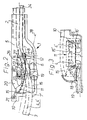
- the frame 1 shown with its left front area in FIG. 1 is fastened from below in the edge area of a roof opening of a motor vehicle which can be closed by a lid. It has two laterally opposite guide rails which run approximately in the longitudinal direction of the vehicle 2, which together with a front, approximately transverse guide part 3 form a U-frame part.
- the U-frame part accommodates two pressure-resistant drive cables which are longitudinally adjustable, of which one drive cable adjusts the cover and the other drive cable longitudinally adjusts a roof part arranged under the cover can effect.
- Adjustment movements of the drive cables take place via a drive, not shown, arranged in front of a transverse water channel 5, which drives the drive cables located in the receiving openings 4, 4 'accordingly.
- the transverse water channel 5 connects the front ends of the guide rails 2.
- an approximately vertical wall 7 separates a front region 6 of the water channel 5 from the latter.
- the approximately vertical wall 7 is approximately U-shaped in a horizontal cross section and has a web wall 8 which runs approximately transversely at the rear, from the sides of which leg walls 9, 9 ′ run approximately to the front and with the front, approximately vertical boundary wall 10 of the water channel 5 are connected.
- the web wall 8 and the leg walls 9, 9 ' are connected to the bottom of the water channel 5 in a watertight manner.
- an inlet opening 14 is formed, through which an area of the U-frame part formed by the guide rail 2 and the guide part 3 is formed runs. Because of the upper inlet opening 14, which is displaced in relation to the front boundary wall 10 of the water channel 5, no sealing is required, even in the case of an inclined one Vehicle to prevent water passage of the water collected in the water channel 5 through the inlet opening 14.
- the drip water cover 11 has on the front and rear edge an upward water-repellent edge 15, 15 'and on its sides downward-facing cover walls 16, 16', which are located laterally outside of the area 6 separated from the approximately vertical wall 7.
- a low-lying corner area 17, which collects water from the water channel 5, is formed between the outer, downward-facing cover wall 16 of the drip water cover 11 and a side wall 18 of the water channel 5, into which a water drainage pipe 19 opens.
- a water drainage opening is formed in the water drainage connection 19 and is connected to a drainage channel.
- the lateral corner area 17, which forms a bottom area of the water channel 5 has a lower height in the area from the front boundary wall 10 of the water channel 5 and the web wall 8 to the underside of the area of the guide rail 2 which adjoins the rear.
- the height of the approximately vertical wall 7 decreases approximately from the boundary wall 10 to the rear.
- the rear upper edge region 12 of the approximately vertical wall 7 is arranged lower to the underside of the region of the guide rail 2 which adjoins the rear.
- the guide rail 2, which forms one leg of the U-frame part lies in its front area from above on the rear upper edge area 12 of the approximately vertical wall 7 and runs directly in front of this edge area 12 to the front and in front of the water channel 5 Area adapted to the course of the front upper edge area of the approximately vertical wall 7 and runs accordingly backwards and downwards.
- the rear area of the drip water cover 11, on the other hand, is adapted to the upper edge of the guide rail 2 which forms one leg of the U-frame part and extends correspondingly upward to the rear.
- a side region of a wind deflector 20 is arranged, which extends in the transverse direction approximately over the entire width of the roof opening.
- the wind deflector 20 is fastened pivotably about a front transverse axis 21 in the water channel 5 and is connected via a lateral pin / slot connection 22 to a pivoting lever 24 which can be pivoted about a rear transverse axis 23 and which is spring-loaded and automatically pushes the wind deflector 20 out of it when the cover is pushed back Issues the storage position in its active position.
- leg walls 9, 9 'of the approximately vertical wall 7 and the deployment lever 24 are arranged laterally outside the guide rail 2 which forms one leg of the U-frame part.
- the deep-lying corner area 17 connected to the water drainage pipe 19 is covered by a suction plate 25 which runs approximately parallel to the bottom of this corner area 17 and runs at a height corresponding to the diameter of the water drainage pipe 19 or the drainage opening formed therein.
- FIG. 2 shows further details.
- the wind deflector 20 is arranged inside the water channel 5.
- the drip water cover 11 forms in its central longitudinal region a trough which serves to receive a side region of the wind deflector 20.
- the approximately vertical wall 7 has a height which decreases from the front boundary wall 10 of the water channel 5 to the rear.
- the contour of the upper edge region of the approximately vertical wall 7 visible in the figure is designated 7 '.
- a support lug 26 is shown on a part which is fastened to the fastening point 27 which can also be seen in FIG. 1 and in A slide part is fixed in the closed position of the cover.
- Line 28 is intended to illustrate the maximum water level in water channel 5, which can result when the vehicle is inclined forward and downward by approximately 15 ° with respect to the horizontal.
- FIG. 3 shows a cross section in the area of the water drainage connector 19, in which the arrangement of the suction plate 25 and the receiving openings 4, 4 'in the guide 2 can be seen in particular.
- the side cover walls 16, 16 'on the drip water cover 11 are formed almost to the bottom of the water channel 5.
- the guide 2 is raised relative to the bottom of the water channel 5.
- the invention can also be implemented in a manner that differs from the exemplary embodiment.
- the number of receiving openings in the guide rail for receiving a drive element is arbitrary.
- a drive element can only be provided on one side.
- the approximately vertical wall can have any course.
- Deviating from the particularly advantageous one-piece design of the two guide rails and the guide part, the two guide rails and the guide part can also be formed by separate parts, wherein the guide parts can be tubular, for example, as in the prior art.
- a wind deflector cannot be provided or formed in any other way.
- the drive can be an electric drive or another drive which, for example, causes an adjustment movement of a drive element by manual actuation of a hand crank drive.
- the drive element can be, for example, a pressure-resistant drive cable or a flexible drive rod.
- the bottom of the water channel in the area of the wind deflector or the corner area opposite the underside of the one adjoining to the rear Area of the guide rail or the area of the drive element located therein are lower.
- the upper edge region of the approximately vertical wall is preferably located at a lower elevation relative to the underside of the region of the guide rail adjoining the rear or of the region of the drive element located therein.
- the suction plate largely prevents air from entering the water outlet nozzle, so that a maximum amount of water can drain through the water outlet nozzle.
- the advantageous suction plate can also be omitted. Walls of the area separated from the approximately vertical wall can be omitted in whole or in part.
- the entry opening for the guide part can be formed in the rear upper region of the approximately vertical wall as a through opening or a recess open at the top.
- the drip water cover can be connected in one piece to the approximately vertical wall or can be connected as a separate part via connecting means or non-positive or form-fitting holding elements to the approximately vertical wall or another wall element of the water channel or a guide rail.
Landscapes
- Engineering & Computer Science (AREA)
- Mechanical Engineering (AREA)
- Seal Device For Vehicle (AREA)
Applications Claiming Priority (2)
| Application Number | Priority Date | Filing Date | Title |
|---|---|---|---|
| DE4444580 | 1994-12-14 | ||
| DE4444580A DE4444580C1 (de) | 1994-12-14 | 1994-12-14 | Rahmen für eine von einem Deckel verschließbare Dachöffnung, insbesondere an einem Kraftfahrzeug |
Publications (2)
| Publication Number | Publication Date |
|---|---|
| EP0716945A1 true EP0716945A1 (fr) | 1996-06-19 |
| EP0716945B1 EP0716945B1 (fr) | 1998-07-29 |
Family
ID=6535821
Family Applications (1)
| Application Number | Title | Priority Date | Filing Date |
|---|---|---|---|
| EP95118738A Expired - Lifetime EP0716945B1 (fr) | 1994-12-14 | 1995-11-29 | Cadre pour une ouverture de toit avec panneau de fermeture, en particulier pour un véhicule automobile |
Country Status (3)
| Country | Link |
|---|---|
| EP (1) | EP0716945B1 (fr) |
| DE (2) | DE4444580C1 (fr) |
| ES (1) | ES2119295T3 (fr) |
Citations (4)
| Publication number | Priority date | Publication date | Assignee | Title |
|---|---|---|---|---|
| GB2180295A (en) * | 1985-09-09 | 1987-03-25 | Webasto Werk Baier Kg W | Pre-assembled installation unit for sliding and raisable roofs for vehicles |
| EP0363912A2 (fr) * | 1988-10-11 | 1990-04-18 | Ohi Seisakusho Co., Ltd. | Structure de guidage d'un couvercle pour un ensemble de toit pare-soleil |
| EP0466529A1 (fr) | 1990-07-09 | 1992-01-15 | WEBASTO HEULIEZ : Société à Responsabilité Limitée | Cadre modulaire pour toits coulissants et/ou entrebâillants guidés par câbles |
| DE4330582C1 (de) * | 1993-09-09 | 1994-10-27 | Webasto Karosseriesysteme | Rahmen eines öffnungsfähigen Fahrzeugdaches |
-
1994
- 1994-12-14 DE DE4444580A patent/DE4444580C1/de not_active Expired - Fee Related
-
1995
- 1995-11-29 DE DE59502977T patent/DE59502977D1/de not_active Expired - Fee Related
- 1995-11-29 ES ES95118738T patent/ES2119295T3/es not_active Expired - Lifetime
- 1995-11-29 EP EP95118738A patent/EP0716945B1/fr not_active Expired - Lifetime
Patent Citations (4)
| Publication number | Priority date | Publication date | Assignee | Title |
|---|---|---|---|---|
| GB2180295A (en) * | 1985-09-09 | 1987-03-25 | Webasto Werk Baier Kg W | Pre-assembled installation unit for sliding and raisable roofs for vehicles |
| EP0363912A2 (fr) * | 1988-10-11 | 1990-04-18 | Ohi Seisakusho Co., Ltd. | Structure de guidage d'un couvercle pour un ensemble de toit pare-soleil |
| EP0466529A1 (fr) | 1990-07-09 | 1992-01-15 | WEBASTO HEULIEZ : Société à Responsabilité Limitée | Cadre modulaire pour toits coulissants et/ou entrebâillants guidés par câbles |
| DE4330582C1 (de) * | 1993-09-09 | 1994-10-27 | Webasto Karosseriesysteme | Rahmen eines öffnungsfähigen Fahrzeugdaches |
Also Published As
| Publication number | Publication date |
|---|---|
| DE59502977D1 (de) | 1998-09-03 |
| DE4444580C1 (de) | 1995-12-21 |
| EP0716945B1 (fr) | 1998-07-29 |
| ES2119295T3 (es) | 1998-10-01 |
Similar Documents
| Publication | Publication Date | Title |
|---|---|---|
| DE19541168C1 (de) | Aufbewahrungseinrichtung | |
| DE3345122C2 (de) | Fahrzeugschiebedach | |
| DE3137191C2 (de) | Windabweisvorrichtung an einem Kraftfahrzeugdach | |
| EP0716946B1 (fr) | Déflecteur de vent pour toit coulissant de véhicule automobile | |
| DE3824942C1 (fr) | ||
| DE2637839C2 (de) | Dachhimmelbefestigung für ein Kraftfahrzeugdach | |
| DE19515412C2 (de) | Sonnendach | |
| DE4227400A1 (de) | Schiebedach | |
| DE2759029C2 (fr) | ||
| DE102009030705A1 (de) | Vorrichtung zur Dachgepäckträger-Montage auf ein Kraftfahrzeug mit Sonnendach | |
| EP1275545B1 (fr) | Toit pour véhicule avec au moins deux éléments rigides pour le toit | |
| DE3936372A1 (de) | Kraftfahrzeug, insbesondere personenkraftwagen | |
| DE2601045A1 (de) | Schiebedachbaugruppe fuer fahrzeuge | |
| DE4214277C2 (de) | Rahmenanordnung für ein Schiebedach, Schiebehebedach, Spoilerdach oder dergleichen | |
| DE1149627B (de) | Ausschwenkbar gelagerter Windabweiser an Kraftfahrzeugen mit Schiebedach | |
| DE3706917A1 (de) | Wasserrinne fuer das schiebe-hebe-dach eines kraftfahrzeuges | |
| DE3524840A1 (de) | Flachbauendes schiebedach fuer kraftfahrzeuge | |
| DE69101347T2 (de) | Durch Kabel geführtes Hebe-Schiebedach mit zusammensetzbarem Rahmen. | |
| DE2702410A1 (de) | Fahrzeugdach mit schiebedach | |
| DE3823316C2 (fr) | ||
| DE4444580C1 (de) | Rahmen für eine von einem Deckel verschließbare Dachöffnung, insbesondere an einem Kraftfahrzeug | |
| DE1156663B (de) | Rahmen fuer starre Schiebedaecher an Kraftfahrzeugen | |
| DE19701682C2 (de) | Fahrzeugdach | |
| DE3924035C1 (fr) | ||
| DE2265454C2 (de) | Dachlüfter mit die Größe der Lüftungsöffnung steuernden Klappen |
Legal Events
| Date | Code | Title | Description |
|---|---|---|---|
| PUAI | Public reference made under article 153(3) epc to a published international application that has entered the european phase |
Free format text: ORIGINAL CODE: 0009012 |
|
| AK | Designated contracting states |
Kind code of ref document: A1 Designated state(s): DE ES FR GB IT |
|
| 17P | Request for examination filed |
Effective date: 19960705 |
|
| GRAG | Despatch of communication of intention to grant |
Free format text: ORIGINAL CODE: EPIDOS AGRA |
|
| 17Q | First examination report despatched |
Effective date: 19971006 |
|
| GRAG | Despatch of communication of intention to grant |
Free format text: ORIGINAL CODE: EPIDOS AGRA |
|
| GRAH | Despatch of communication of intention to grant a patent |
Free format text: ORIGINAL CODE: EPIDOS IGRA |
|
| GRAH | Despatch of communication of intention to grant a patent |
Free format text: ORIGINAL CODE: EPIDOS IGRA |
|
| GRAA | (expected) grant |
Free format text: ORIGINAL CODE: 0009210 |
|
| AK | Designated contracting states |
Kind code of ref document: B1 Designated state(s): DE ES FR GB IT |
|
| GBT | Gb: translation of ep patent filed (gb section 77(6)(a)/1977) |
Effective date: 19980729 |
|
| REF | Corresponds to: |
Ref document number: 59502977 Country of ref document: DE Date of ref document: 19980903 |
|
| ET | Fr: translation filed | ||
| REG | Reference to a national code |
Ref country code: ES Ref legal event code: FG2A Ref document number: 2119295 Country of ref document: ES Kind code of ref document: T3 |
|
| PLBE | No opposition filed within time limit |
Free format text: ORIGINAL CODE: 0009261 |
|
| STAA | Information on the status of an ep patent application or granted ep patent |
Free format text: STATUS: NO OPPOSITION FILED WITHIN TIME LIMIT |
|
| 26N | No opposition filed | ||
| REG | Reference to a national code |
Ref country code: GB Ref legal event code: IF02 |
|
| PGFP | Annual fee paid to national office [announced via postgrant information from national office to epo] |
Ref country code: DE Payment date: 20031210 Year of fee payment: 9 |
|
| PGFP | Annual fee paid to national office [announced via postgrant information from national office to epo] |
Ref country code: ES Payment date: 20041029 Year of fee payment: 10 |
|
| PGFP | Annual fee paid to national office [announced via postgrant information from national office to epo] |
Ref country code: GB Payment date: 20041125 Year of fee payment: 10 |
|
| PGFP | Annual fee paid to national office [announced via postgrant information from national office to epo] |
Ref country code: FR Payment date: 20041129 Year of fee payment: 10 |
|
| PG25 | Lapsed in a contracting state [announced via postgrant information from national office to epo] |
Ref country code: DE Free format text: LAPSE BECAUSE OF NON-PAYMENT OF DUE FEES Effective date: 20050601 |
|
| PG25 | Lapsed in a contracting state [announced via postgrant information from national office to epo] |
Ref country code: IT Free format text: LAPSE BECAUSE OF NON-PAYMENT OF DUE FEES Effective date: 20051129 Ref country code: GB Free format text: LAPSE BECAUSE OF NON-PAYMENT OF DUE FEES Effective date: 20051129 |
|
| PG25 | Lapsed in a contracting state [announced via postgrant information from national office to epo] |
Ref country code: ES Free format text: LAPSE BECAUSE OF NON-PAYMENT OF DUE FEES Effective date: 20051130 |
|
| GBPC | Gb: european patent ceased through non-payment of renewal fee |
Effective date: 20051129 |
|
| PG25 | Lapsed in a contracting state [announced via postgrant information from national office to epo] |
Ref country code: FR Free format text: LAPSE BECAUSE OF NON-PAYMENT OF DUE FEES Effective date: 20060731 |
|
| REG | Reference to a national code |
Ref country code: FR Ref legal event code: ST Effective date: 20060731 |
|
| REG | Reference to a national code |
Ref country code: ES Ref legal event code: FD2A Effective date: 20051130 |