EP0716979A2 - Appareil pour épandre des matières - Google Patents
Appareil pour épandre des matières Download PDFInfo
- Publication number
- EP0716979A2 EP0716979A2 EP95119433A EP95119433A EP0716979A2 EP 0716979 A2 EP0716979 A2 EP 0716979A2 EP 95119433 A EP95119433 A EP 95119433A EP 95119433 A EP95119433 A EP 95119433A EP 0716979 A2 EP0716979 A2 EP 0716979A2
- Authority
- EP
- European Patent Office
- Prior art keywords
- spreading
- legs
- container
- ring
- plate
- Prior art date
- Legal status (The legal status is an assumption and is not a legal conclusion. Google has not performed a legal analysis and makes no representation as to the accuracy of the status listed.)
- Ceased
Links
Images



Classifications
-
- B—PERFORMING OPERATIONS; TRANSPORTING
- B65—CONVEYING; PACKING; STORING; HANDLING THIN OR FILAMENTARY MATERIAL
- B65G—TRANSPORT OR STORAGE DEVICES, e.g. CONVEYORS FOR LOADING OR TIPPING, SHOP CONVEYOR SYSTEMS OR PNEUMATIC TUBE CONVEYORS
- B65G31/00—Mechanical throwing machines for articles or solid materials
- B65G31/04—Mechanical throwing machines for articles or solid materials comprising discs, drums, or like rotary impellers
-
- A—HUMAN NECESSITIES
- A01—AGRICULTURE; FORESTRY; ANIMAL HUSBANDRY; HUNTING; TRAPPING; FISHING
- A01C—PLANTING; SOWING; FERTILISING
- A01C17/00—Fertilisers or seeders with centrifugal wheels
- A01C17/001—Centrifugal throwing devices with a vertical axis
-
- B—PERFORMING OPERATIONS; TRANSPORTING
- B05—SPRAYING OR ATOMISING IN GENERAL; APPLYING FLUENT MATERIALS TO SURFACES, IN GENERAL
- B05B—SPRAYING APPARATUS; ATOMISING APPARATUS; NOZZLES
- B05B3/00—Spraying or sprinkling apparatus with moving outlet elements or moving deflecting elements
- B05B3/02—Spraying or sprinkling apparatus with moving outlet elements or moving deflecting elements with rotating elements
- B05B3/10—Spraying or sprinkling apparatus with moving outlet elements or moving deflecting elements with rotating elements discharging over substantially the whole periphery of the rotating member
- B05B3/1007—Spraying or sprinkling apparatus with moving outlet elements or moving deflecting elements with rotating elements discharging over substantially the whole periphery of the rotating member characterised by the rotating member
-
- B—PERFORMING OPERATIONS; TRANSPORTING
- B64—AIRCRAFT; AVIATION; COSMONAUTICS
- B64D—EQUIPMENT FOR FITTING IN OR TO AIRCRAFT; FLIGHT SUITS; PARACHUTES; ARRANGEMENT OR MOUNTING OF POWER PLANTS OR PROPULSION TRANSMISSIONS IN AIRCRAFT
- B64D1/00—Dropping, ejecting, releasing or receiving articles, liquids, or the like, in flight
- B64D1/16—Dropping or releasing powdered, liquid, or gaseous matter, e.g. for fire-fighting
-
- B—PERFORMING OPERATIONS; TRANSPORTING
- B65—CONVEYING; PACKING; STORING; HANDLING THIN OR FILAMENTARY MATERIAL
- B65D—CONTAINERS FOR STORAGE OR TRANSPORT OF ARTICLES OR MATERIALS, e.g. BAGS, BARRELS, BOTTLES, BOXES, CANS, CARTONS, CRATES, DRUMS, JARS, TANKS, HOPPERS, FORWARDING CONTAINERS; ACCESSORIES, CLOSURES, OR FITTINGS THEREFOR; PACKAGING ELEMENTS; PACKAGES
- B65D88/00—Large containers
- B65D88/26—Hoppers, i.e. containers having funnel-shaped discharge sections
- B65D88/30—Hoppers, i.e. containers having funnel-shaped discharge sections specially adapted to facilitate transportation from one utilisation site to another
-
- B—PERFORMING OPERATIONS; TRANSPORTING
- B65—CONVEYING; PACKING; STORING; HANDLING THIN OR FILAMENTARY MATERIAL
- B65G—TRANSPORT OR STORAGE DEVICES, e.g. CONVEYORS FOR LOADING OR TIPPING, SHOP CONVEYOR SYSTEMS OR PNEUMATIC TUBE CONVEYORS
- B65G65/00—Loading or unloading
- B65G65/30—Methods or devices for filling or emptying bunkers, hoppers, tanks, or like containers, of interest apart from their use in particular chemical or physical processes or their application in particular machines, e.g. not covered by a single other subclass
- B65G65/34—Emptying devices
- B65G65/40—Devices for emptying otherwise than from the top
- B65G65/48—Devices for emptying otherwise than from the top using other rotating means, e.g. rotating pressure sluices in pneumatic systems
- B65G65/4809—Devices for emptying otherwise than from the top using other rotating means, e.g. rotating pressure sluices in pneumatic systems rotating about a substantially vertical axis
- B65G65/4818—Devices for emptying otherwise than from the top using other rotating means, e.g. rotating pressure sluices in pneumatic systems rotating about a substantially vertical axis and having the form of rotating tables or pans
- B65G65/4827—Devices for emptying otherwise than from the top using other rotating means, e.g. rotating pressure sluices in pneumatic systems rotating about a substantially vertical axis and having the form of rotating tables or pans with particular surface features, e.g. ribs, roughening
Definitions
- the invention is based on the object of creating a very light device which can withstand the stresses described in 1 above and is easy to repair. This object is achieved by the features specified in claim 1.
- the subclaims contain advantageous developments.
- the device according to the invention meets these tough requirements. This results in immense economic advantages. It should also be pointed out that there is a significantly improved ecological balance (application performance versus energy consumption).
- the spreading of the spreading material is paid almost exclusively per unit of weight.
- the weight to be transported in addition to factors that cannot be influenced such as weather and flight distances) is the most important limiting factor.
- the approx. 12% weight advantage (reference value is the total weight of the spreading device and spreading material) with the The device according to the invention is to be explained here as a direct economic advantage using a practical example with absolute numbers.
- the load on the hook is 900 kg.
- the typical spreading systems for this machine weigh between 170 Kp and 200 Kp. If the lowest value (170 Kp) is used, the machine can transport 730 Kp net of spreading material.
- the usual annual spreading output is the production of approx. 25,000 tons.
- a spreader according to the invention weighs about 70 kg for this total payload, and this when all the conditions specified in the catalog of requirements are met. 34,000 flights, with a system that is 100 kg lighter, result in an additional output of 3,400 tons with the same amount of resources (personnel and material).
- the delivery of one ton is paid at approximately DM 70.00.
- the direct economic advantage thus amounts to approximately DM 238,000 per year.
- the expected price of the device is almost identical to that for the system previously used.
- FIG. 1 shows a side view of the device. It shows two of the three legs 1 made of aluminum tube (the third is omitted for the sake of simplicity), a ring made of aluminum tube 2, a conical section-shaped container 3 attached to it, one of three support parts 4 made of aluminum tube, a diffuser 5 with drive motor 6, one in FIG. 1 only indicated hanger 7, schematically a closure 8 for opening the container and two of six tension cables 9th
- connection parts according to FIG. 4 are attached.
- the pipe part 10 is inserted into the upper end of the leg 1.
- the part 11 lying transversely thereto lies in the assembled state on the ring and therefore has a shape corresponding to the outer contour of the ring 2.
- the part 11 is preferably connected to the ring by two clamps.
- Connection parts according to FIG. 5 are used to produce the connection of the support tubes to the legs. It consists of a part 12 adapted to the outer contour of the legs, which abuts the leg 1 in the assembled state and can be connected to these with clamps.
- the two parts 13 and 14 attached to part 12 are arranged and shaped such that they are mounted in the Project the condition into the support tubes 4 and rest on the inner wall.
- the tensioning cables 9 are fastened at the top by means of tabs to one leg 1 (or directly to the ring 2) and each lead to the connection point of the neighboring leg with the support tubes. They are each guided above the legs 1 and thus press the legs against two support tubes 4 each.
- the tensioned tension cables give the construction the stability required for rough use.
- the tensioning cables can absorb the bending loads and bending moments without these having a destructive effect on the other parts of the device. They can be attached to the support tubes with the legs at the connection points of the support tubes 4. A more favorable design will be explained later in connection with FIG. 3.
- Fig. 2 shows the storage or suspension of the lens 5 together with the drive motor 6 and seen from below on the device (disc 5 not shown).
- the disc 5 with the hydraulic motor 6 is mounted on a plate 16 which is held by six tensioning cables 15.
- the tensioning cables 15 are fastened to the connecting points of the legs 1 with the support tubes, preferably in the manner as can be seen in FIG. 3.
- a leg 1 and parts of two support tubes 4 are drawn out there.
- a rubber roller 17 is arranged between the support tubes 4, the shaft 18 of which projects beyond the rubber roller on both sides.
- the tensioning cables 15 leading to the leg 1 shown are guided around the leg 1 and connected (hooked in) to the lower end of the shaft 18.
- the corresponding tensioning cables 9 are preferably also guided around the leg 1 and also connected to the two ends of the shaft 18.
- forces acting on the device from outside lead to the stabilization of the connection points of the parts by the introduction of these forces via the tensioning cables to the connection points (joints). The effects are reduced (dampened) by the rubber roller.
- the container 3 is drawn out. It consists of ultra-high molecular weight polyethylene and is made up of several riveted (19) sheets. At the top it is connected to ring 2. In the lower area 3 a, the container is reinforced by a multi-layer carbon fiber layer. The carbon fiber fabric is wound onto the outer wall of the container and impregnated (laminated) with synthetic resin. Because of the rivets, it is not possible to detach the layer downwards. Fastening parts 20, to which e.g. a vibrator 21 can be screwed on. The property of the carbon fiber laminate (high strength and high hardness) has an advantageous effect on the transmission of the vibration generated by the vibrator to the spreading material.
- FIG. 6 and 7 show a simple but very functional possibility for the formation of the closure of the outlet opening.
- This is on one leg 1 in the vertical pivotally mounted (point 1 a) and consists of a cylinder 22 with an actuating piston together with the piston rod 23 and a closure plate 24 attached to it, which is mounted on two bearing cables 25.
- the closure plate 24 pivots against the force of a spring 26 in front of the opening of the container 3. Without the application of pressure, it is in the position shown in FIG. 6 due to the action of the spring 26.
- the bearing cables 25 are attached to the ring 2. As can be easily seen from FIG.
- the points determined by the rope ends 25 and thus the closure plate 24 describe an arc when the cylinder 22 is actuated. In order to avoid a collision of the closure plate with the container opening, this opening is chamfered (angle 27). In the basic position (closure closed), the closure plate 24 and opening form a line. Damping is preferably provided on the legs of the spreader. These dampers preferably work in the manner of an air pump: when the legs hit the ground, the contact surfaces actuate a piston via a piston rod, whereby this piston is displaced in a cylinder against the force of a spring and the compressed air volume. The compressed air then escapes via an adjustable throttle. Only when the helicopter picks up the container again does the spring return the piston and thus the contact patches to the starting position.
- the worn spreading webs can easily be replaced on site.
- These are preferably made from a material that greatly reduces the need for replacement, ie is subject to little wear.
- the disc part of the spreading disc does wear out much less than the attached spreading parts and can therefore be easily made of metal. Nevertheless, it has proven to be advantageous to also manufacture the pane part itself from the same material as the scatter parts. This design of the spreading disc could also be used with other spreading devices than that of FIGS. 1 to 5.
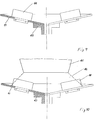
- 8a shows a top view of the diffusing screen 5 designed according to the invention.
- a disk 30 for example made of metal, but preferably made of a thermoplastic synthetic material, in particular of ultra-high-molecular polyethylene, and of essentially radially extending, curved scattering webs 32 placed on the disk 30 During operation, the spreading disc runs in the direction of rotation shown by an arrow. Preferably, the curved course of the webs is such that the radius of the bend becomes smaller as seen from the inside out.
- 8b which shows a section of the lens 5 in the perspective layer in the as-yet unassembled state
- the disk 30 has essentially radially extending recesses 31 and that the scattering webs 32 Have parts 32a that fit into these recesses 31 (the expression radial recesses should also include a design in which the recess 31 is divided into two or more partial recesses and the part 32a is adapted accordingly).
- 8b and 8c which shows a section through part of the spreading disc, it can be seen that the parts 32a have openings 33 through which locking pins 34 are inserted for fastening the spreading webs.
- a diffuser designed according to the invention is shown partially in section. It consists of a body 41, the surface of which has the shape of a flat (large base, low height) truncated cone.
- the body 41 In the installed state, the body 41, as shown, is connected upside down to the drive motor underneath.
- the attachment to the motor is a fleece 43.
- the body 41 lacks the base area, so that it has an approximately plate-like shape overall.
- On the Spreading surfaces 44 are attached to the plate surface.
- the connection of the webs 44 to the plate 41 can be carried out as described with reference to FIG. 8 and indicated in FIG. 9.
- the scatter bars, but also the plate, as proposed there, can consist of thermoplastic, in particular of ultra-high molecular weight polyethylene.
- Fig. 10 the currently non-driven spreading disc 41 is shown with its spreading webs 44 opposite the lower end of the spreading container 45.
- Spreading material has emerged from the container and forms a spreading material cone 46 (bulk cone).
- the distance between the lens 41 to the opening of the container 45 and the large diameter of the plate 41 are coordinated so that the scattering cone 46 does not reach the edge of the plate. In any case, the diameter of the plate must be significantly larger than the opening of the container. On the other hand, the distance between the plate 41 and the opening of the container 45 must not be very large.
- a base plate 50 is provided, on which the spreading webs 51 are fastened, for example as shown in FIG. 8.
- a cone-shaped body (plate) 52 with recesses 53 corresponding to the scattering webs is now placed over the scattering webs 51.
- the plate is again in Fig. 11b drawn out separately.
- the inner surface 54 of the plate lies on the disc 50 and is connected to it.
- the spreading ridges must be higher in this embodiment. They have such a shape that their upper edges 55 run approximately parallel to the surface of the plate.
- the plate 52 supports the spreading webs 51 fastened in the base plate 50. This is helpful if stones, lumps and the like are present in the spreading material.
Landscapes
- Engineering & Computer Science (AREA)
- Mechanical Engineering (AREA)
- Aviation & Aerospace Engineering (AREA)
- Life Sciences & Earth Sciences (AREA)
- Soil Sciences (AREA)
- Environmental Sciences (AREA)
- Tents Or Canopies (AREA)
- Filling Or Emptying Of Bunkers, Hoppers, And Tanks (AREA)
Applications Claiming Priority (8)
| Application Number | Priority Date | Filing Date | Title |
|---|---|---|---|
| DE4444129 | 1994-12-12 | ||
| DE19944444129 DE4444129C1 (de) | 1994-12-12 | 1994-12-12 | Gerät zum Ausbringen von Streugut |
| DE19944444127 DE4444127C2 (de) | 1994-12-12 | 1994-12-12 | Gerät zum Ausbringen von Streugut |
| DE4444127 | 1994-12-12 | ||
| DE19944444128 DE4444128C1 (de) | 1994-12-12 | 1994-12-12 | Gerät zum Ausbringen von Streugut |
| DE4444128 | 1994-12-12 | ||
| DE19534565 | 1995-09-18 | ||
| DE19534565 | 1995-09-18 |
Publications (2)
| Publication Number | Publication Date |
|---|---|
| EP0716979A2 true EP0716979A2 (fr) | 1996-06-19 |
| EP0716979A3 EP0716979A3 (fr) | 1998-01-07 |
Family
ID=27436109
Family Applications (1)
| Application Number | Title | Priority Date | Filing Date |
|---|---|---|---|
| EP95119433A Ceased EP0716979A3 (fr) | 1994-12-12 | 1995-12-09 | Appareil pour épandre des matières |
Country Status (2)
| Country | Link |
|---|---|
| US (1) | US5722591A (fr) |
| EP (1) | EP0716979A3 (fr) |
Cited By (7)
| Publication number | Priority date | Publication date | Assignee | Title |
|---|---|---|---|---|
| CN101712397B (zh) * | 2009-11-27 | 2013-11-27 | 中国电力科学研究院 | 一种用于直升机吊运混凝土的吊罐 |
| CN103496576A (zh) * | 2013-09-13 | 2014-01-08 | 宜兴天力化工纳米科技有限公司 | 一种石灰出灰装置 |
| CN105197513A (zh) * | 2015-09-24 | 2015-12-30 | 长沙正能现代农业研发有限公司 | 一种智能投食机 |
| CN109383804A (zh) * | 2018-10-09 | 2019-02-26 | 成都戎创航空科技有限公司 | 一种定向播种的无人机 |
| CN110356554A (zh) * | 2019-08-26 | 2019-10-22 | 通辽市神鹰飞机制造有限公司 | 飞机播种出料控制装置 |
| CN110947444A (zh) * | 2019-12-06 | 2020-04-03 | 湖北京山群健米业有限公司 | 一种大米碾米加工米皮糠收集处理装置 |
| EP4520156A1 (fr) * | 2023-09-07 | 2025-03-12 | ANNABURGER Nutzfahrzeug GmbH | Dispositif d'épandage pour un véhicule d'épandage agricole ainsi que véhicule d'épandage agricole |
Families Citing this family (10)
| Publication number | Priority date | Publication date | Assignee | Title |
|---|---|---|---|---|
| US6135036A (en) * | 1997-05-02 | 2000-10-24 | Cyclone Manufacturing Company | Broadcast spreader with replaceable spinner |
| US6726131B2 (en) * | 2001-12-27 | 2004-04-27 | All-State Industries, Inc. | Rotatable distribution plate for particulate material |
| US6672518B1 (en) | 2002-06-12 | 2004-01-06 | Ronald D. Mudge | Spinning disc resin atomizer |
| US20040265098A1 (en) * | 2003-06-26 | 2004-12-30 | Depierri Thomas M. | Bulk material loading device |
| GB2424164A (en) * | 2005-03-19 | 2006-09-20 | Luke Stuart Ring | Aerial mulch spreader |
| US9617000B2 (en) * | 2012-11-26 | 2017-04-11 | Texas Transland LLC | Sliding door gatebox and detachable seeder plate |
| US9266612B2 (en) | 2012-11-26 | 2016-02-23 | Texas Transland LLC | Molded spreader for an aircraft gatebox |
| CN104176254B (zh) * | 2014-08-06 | 2016-08-17 | 华南农业大学 | 一种适于无人机撒播作业的机载装置及撒播方法 |
| JP2016064901A (ja) * | 2014-09-25 | 2016-04-28 | 株式会社松井製作所 | 粉粒体材料の貯留装置及びこれを備えた粉粒体材料の計量装置 |
| GB202214596D0 (en) * | 2022-10-04 | 2022-11-16 | Simcox Graham | Apparatus for use in spreading of materials |
Family Cites Families (21)
| Publication number | Priority date | Publication date | Assignee | Title |
|---|---|---|---|---|
| US940891A (en) * | 1908-12-30 | 1909-11-23 | Sanford A Plummer | Seed-sower. |
| US3083879A (en) * | 1958-03-24 | 1963-04-02 | Clarence B Coleman | Dispensing bin |
| US3204896A (en) * | 1964-03-26 | 1965-09-07 | Granular material spreader apparatus for helicopters | |
| NL6702499A (fr) * | 1967-02-20 | 1968-08-21 | ||
| US3512721A (en) * | 1968-01-29 | 1970-05-19 | Transland Aircraft Inc | Spreader for flowable material |
| US3463398A (en) * | 1968-11-21 | 1969-08-26 | Evergreen Helicopters Inc | Material spreader device for helicopters |
| US3688952A (en) * | 1970-03-20 | 1972-09-05 | Transland Aircraft Inc | Spreader |
| RO55366A2 (fr) * | 1971-04-05 | 1973-07-20 | ||
| CH573839A5 (fr) * | 1973-06-04 | 1976-03-31 | Sarbach Raymond | |
| US4099676A (en) * | 1976-06-14 | 1978-07-11 | Sterner Aero Aktiebolag | Apparatus for spreading fertilizer, plant killer or similar agents from an aircraft |
| DE2628251C3 (de) * | 1976-06-24 | 1982-03-25 | Sessler, Hans, 8851 Donaumünster | Transportbehälter zur schnellen Füllung und Entleerung |
| JPS5951480B2 (ja) * | 1976-12-02 | 1984-12-14 | 川崎重工業株式会社 | ヘリコプタ用吊下げ式散布装置 |
| US4260108A (en) * | 1978-08-23 | 1981-04-07 | Biogenesis, Inc. | Method and apparatus for airborne release of insect eggs |
| US4382568A (en) * | 1980-03-24 | 1983-05-10 | Schertz Robert O | Airplane spreader apparatus |
| FI62501C (fi) * | 1980-08-04 | 1983-01-10 | Perusyhtyme Oy | Noedtoemningsmekanism foer flygplans centrifugalsridare |
| IT215667Z2 (it) * | 1988-06-23 | 1990-10-22 | Barbieri Silvano B S | Struttura di macchina per spargere concimi, sementi, sale e sabbia. |
| DE4216010C2 (de) * | 1992-05-14 | 1995-04-20 | Flath Reiner Dipl Agr Ing | Verfahren und Vorrichtung zum dosierten Ausbringen von rieselfähigem Gut mit einem Luftfahrzeug |
| AT397235B (de) * | 1992-05-21 | 1994-02-25 | Renzler Walter | Behälter |
| DE9419863U1 (de) * | 1994-12-12 | 1995-03-30 | Folger, Wolfgang, 68766 Hockenheim | Gerät zum Ausbringen von Streugut |
| DE4444127C2 (de) * | 1994-12-12 | 1996-11-28 | Wolfgang Folger | Gerät zum Ausbringen von Streugut |
| DE9419861U1 (de) * | 1994-12-12 | 1995-03-30 | Folger, Wolfgang, 68766 Hockenheim | Gerät zum Ausbringen von Streugut |
-
1995
- 1995-11-09 US US08/555,607 patent/US5722591A/en not_active Expired - Fee Related
- 1995-12-09 EP EP95119433A patent/EP0716979A3/fr not_active Ceased
Cited By (7)
| Publication number | Priority date | Publication date | Assignee | Title |
|---|---|---|---|---|
| CN101712397B (zh) * | 2009-11-27 | 2013-11-27 | 中国电力科学研究院 | 一种用于直升机吊运混凝土的吊罐 |
| CN103496576A (zh) * | 2013-09-13 | 2014-01-08 | 宜兴天力化工纳米科技有限公司 | 一种石灰出灰装置 |
| CN105197513A (zh) * | 2015-09-24 | 2015-12-30 | 长沙正能现代农业研发有限公司 | 一种智能投食机 |
| CN109383804A (zh) * | 2018-10-09 | 2019-02-26 | 成都戎创航空科技有限公司 | 一种定向播种的无人机 |
| CN110356554A (zh) * | 2019-08-26 | 2019-10-22 | 通辽市神鹰飞机制造有限公司 | 飞机播种出料控制装置 |
| CN110947444A (zh) * | 2019-12-06 | 2020-04-03 | 湖北京山群健米业有限公司 | 一种大米碾米加工米皮糠收集处理装置 |
| EP4520156A1 (fr) * | 2023-09-07 | 2025-03-12 | ANNABURGER Nutzfahrzeug GmbH | Dispositif d'épandage pour un véhicule d'épandage agricole ainsi que véhicule d'épandage agricole |
Also Published As
| Publication number | Publication date |
|---|---|
| US5722591A (en) | 1998-03-03 |
| EP0716979A3 (fr) | 1998-01-07 |
Similar Documents
| Publication | Publication Date | Title |
|---|---|---|
| EP0716979A2 (fr) | Appareil pour épandre des matières | |
| DE102008062648B4 (de) | Teleskopierbarer Kranausleger | |
| DE4420855A1 (de) | Schaufelbrechwerk | |
| EP3478620A1 (fr) | Installation d'ascenseur, se présentant en particulier sous forme d'un système de levage à grimpage, comprenant un toit de protection de conception spéciale | |
| EP1268037B1 (fr) | Silo de reception et/ou dispositif de filtrage pour produits pulverulents combustibles | |
| DE4334658C2 (de) | Windpaddelanlage | |
| DE4444127C2 (de) | Gerät zum Ausbringen von Streugut | |
| DE1531920A1 (de) | Siloanlage | |
| DE102014113587A1 (de) | Verfahren zum Sieben von schüttbarem Siebgut und Siebvorrichtung | |
| DE2949447B1 (de) | Axialventilator,insbesondere zur Bodenfrostbekaempfung | |
| DE9419863U1 (de) | Gerät zum Ausbringen von Streugut | |
| DE102008044633A1 (de) | Dämpfungssystem für eine schwimmfähige Struktur | |
| DE804087C (de) | Verfahren und Einrichtung zum Entladen von Schuettgut aus Fahrzeugen | |
| EP0571355B1 (fr) | Réservoir | |
| DE9408206U1 (de) | Tragbare Seilwinde mit Hydraulikantrieb | |
| EP1491703B1 (fr) | Godet de grue pour le transport de matériaux de construction | |
| DE102016111285A1 (de) | Panzerungselement zur Anordnung an einem Fahrzeug | |
| DE3780397T2 (de) | Schlegel fuer streuer. | |
| DE4444128C1 (de) | Gerät zum Ausbringen von Streugut | |
| DE9419861U1 (de) | Gerät zum Ausbringen von Streugut | |
| DE102010006427A1 (de) | Einrichtung zum Abbau von Innenschornsteinen in Industrieschornsteinen und ähnlichen Bauwerken | |
| DE2209276C3 (de) | Zweimassen-Schwingförderer | |
| DE427304C (de) | Gestell fuer freischwingende Zwillings-Plansichter mit oberem Antrieb | |
| DE3010443C2 (de) | Einrichtung zum Austragen von Material aus einem Behälter | |
| DE10342818A1 (de) | Am Lasthaken eines Luftfahrzeugs mitzuführendes Gerät zum Ausbringen von Streugut |
Legal Events
| Date | Code | Title | Description |
|---|---|---|---|
| PUAI | Public reference made under article 153(3) epc to a published international application that has entered the european phase |
Free format text: ORIGINAL CODE: 0009012 |
|
| AK | Designated contracting states |
Kind code of ref document: A2 Designated state(s): BE DE ES FR GB GR IT NL PT |
|
| PUAL | Search report despatched |
Free format text: ORIGINAL CODE: 0009013 |
|
| AK | Designated contracting states |
Kind code of ref document: A3 Designated state(s): BE DE ES FR GB GR IT NL PT |
|
| 17P | Request for examination filed |
Effective date: 19980204 |
|
| 17Q | First examination report despatched |
Effective date: 20010202 |
|
| STAA | Information on the status of an ep patent application or granted ep patent |
Free format text: STATUS: THE APPLICATION HAS BEEN REFUSED |
|
| 18R | Application refused |
Effective date: 20030609 |