EP0717178A2 - Betrieb eines katalytischen Konverters - Google Patents
Betrieb eines katalytischen Konverters Download PDFInfo
- Publication number
- EP0717178A2 EP0717178A2 EP95117896A EP95117896A EP0717178A2 EP 0717178 A2 EP0717178 A2 EP 0717178A2 EP 95117896 A EP95117896 A EP 95117896A EP 95117896 A EP95117896 A EP 95117896A EP 0717178 A2 EP0717178 A2 EP 0717178A2
- Authority
- EP
- European Patent Office
- Prior art keywords
- heater
- catalyst
- honeycomb structure
- temperature
- catalytic converter
- Prior art date
- Legal status (The legal status is an assumption and is not a legal conclusion. Google has not performed a legal analysis and makes no representation as to the accuracy of the status listed.)
- Granted
Links
Images

Classifications
-
- B—PERFORMING OPERATIONS; TRANSPORTING
- B01—PHYSICAL OR CHEMICAL PROCESSES OR APPARATUS IN GENERAL
- B01D—SEPARATION
- B01D53/00—Separation of gases or vapours; Recovering vapours of volatile solvents from gases; Chemical or biological purification of waste gases, e.g. engine exhaust gases, smoke, fumes, flue gases, aerosols
- B01D53/34—Chemical or biological purification of waste gases
- B01D53/92—Chemical or biological purification of waste gases of engine exhaust gases
- B01D53/94—Chemical or biological purification of waste gases of engine exhaust gases by catalytic processes
- B01D53/9445—Simultaneously removing carbon monoxide, hydrocarbons or nitrogen oxides making use of three-way catalysts [TWC] or four-way-catalysts [FWC]
-
- F—MECHANICAL ENGINEERING; LIGHTING; HEATING; WEAPONS; BLASTING
- F01—MACHINES OR ENGINES IN GENERAL; ENGINE PLANTS IN GENERAL; STEAM ENGINES
- F01N—GAS-FLOW SILENCERS OR EXHAUST APPARATUS FOR MACHINES OR ENGINES IN GENERAL; GAS-FLOW SILENCERS OR EXHAUST APPARATUS FOR INTERNAL-COMBUSTION ENGINES
- F01N3/00—Exhaust or silencing apparatus having means for purifying, rendering innocuous, or otherwise treating exhaust
- F01N3/08—Exhaust or silencing apparatus having means for purifying, rendering innocuous, or otherwise treating exhaust for rendering innocuous
- F01N3/10—Exhaust or silencing apparatus having means for purifying, rendering innocuous, or otherwise treating exhaust for rendering innocuous by thermal or catalytic conversion of noxious components of exhaust
- F01N3/18—Exhaust or silencing apparatus having means for purifying, rendering innocuous, or otherwise treating exhaust for rendering innocuous by thermal or catalytic conversion of noxious components of exhaust characterised by methods of operation; Control
- F01N3/20—Exhaust or silencing apparatus having means for purifying, rendering innocuous, or otherwise treating exhaust for rendering innocuous by thermal or catalytic conversion of noxious components of exhaust characterised by methods of operation; Control specially adapted for catalytic conversion
- F01N3/2006—Periodically heating or cooling catalytic reactors, e.g. at cold starting or overheating
- F01N3/2013—Periodically heating or cooling catalytic reactors, e.g. at cold starting or overheating using electric or magnetic heating means
- F01N3/2026—Periodically heating or cooling catalytic reactors, e.g. at cold starting or overheating using electric or magnetic heating means directly electrifying the catalyst substrate, i.e. heating the electrically conductive catalyst substrate by joule effect
-
- F—MECHANICAL ENGINEERING; LIGHTING; HEATING; WEAPONS; BLASTING
- F01—MACHINES OR ENGINES IN GENERAL; ENGINE PLANTS IN GENERAL; STEAM ENGINES
- F01N—GAS-FLOW SILENCERS OR EXHAUST APPARATUS FOR MACHINES OR ENGINES IN GENERAL; GAS-FLOW SILENCERS OR EXHAUST APPARATUS FOR INTERNAL-COMBUSTION ENGINES
- F01N3/00—Exhaust or silencing apparatus having means for purifying, rendering innocuous, or otherwise treating exhaust
- F01N3/08—Exhaust or silencing apparatus having means for purifying, rendering innocuous, or otherwise treating exhaust for rendering innocuous
- F01N3/10—Exhaust or silencing apparatus having means for purifying, rendering innocuous, or otherwise treating exhaust for rendering innocuous by thermal or catalytic conversion of noxious components of exhaust
- F01N3/18—Exhaust or silencing apparatus having means for purifying, rendering innocuous, or otherwise treating exhaust for rendering innocuous by thermal or catalytic conversion of noxious components of exhaust characterised by methods of operation; Control
- F01N3/22—Control of additional air supply only, e.g. using by-passes or variable air pump drives
-
- H—ELECTRICITY
- H05—ELECTRIC TECHNIQUES NOT OTHERWISE PROVIDED FOR
- H05B—ELECTRIC HEATING; ELECTRIC LIGHT SOURCES NOT OTHERWISE PROVIDED FOR; CIRCUIT ARRANGEMENTS FOR ELECTRIC LIGHT SOURCES, IN GENERAL
- H05B3/00—Ohmic-resistance heating
- H05B3/10—Heating elements characterised by the composition or nature of the materials or by the arrangement of the conductor
- H05B3/12—Heating elements characterised by the composition or nature of the materials or by the arrangement of the conductor characterised by the composition or nature of the conductive material
-
- B—PERFORMING OPERATIONS; TRANSPORTING
- B01—PHYSICAL OR CHEMICAL PROCESSES OR APPARATUS IN GENERAL
- B01D—SEPARATION
- B01D2251/00—Reactants
- B01D2251/10—Oxidants
-
- F—MECHANICAL ENGINEERING; LIGHTING; HEATING; WEAPONS; BLASTING
- F01—MACHINES OR ENGINES IN GENERAL; ENGINE PLANTS IN GENERAL; STEAM ENGINES
- F01N—GAS-FLOW SILENCERS OR EXHAUST APPARATUS FOR MACHINES OR ENGINES IN GENERAL; GAS-FLOW SILENCERS OR EXHAUST APPARATUS FOR INTERNAL-COMBUSTION ENGINES
- F01N3/00—Exhaust or silencing apparatus having means for purifying, rendering innocuous, or otherwise treating exhaust
- F01N3/08—Exhaust or silencing apparatus having means for purifying, rendering innocuous, or otherwise treating exhaust for rendering innocuous
- F01N3/10—Exhaust or silencing apparatus having means for purifying, rendering innocuous, or otherwise treating exhaust for rendering innocuous by thermal or catalytic conversion of noxious components of exhaust
- F01N3/24—Exhaust or silencing apparatus having means for purifying, rendering innocuous, or otherwise treating exhaust for rendering innocuous by thermal or catalytic conversion of noxious components of exhaust characterised by constructional aspects of converting apparatus
- F01N3/30—Arrangements for supply of additional air
-
- Y—GENERAL TAGGING OF NEW TECHNOLOGICAL DEVELOPMENTS; GENERAL TAGGING OF CROSS-SECTIONAL TECHNOLOGIES SPANNING OVER SEVERAL SECTIONS OF THE IPC; TECHNICAL SUBJECTS COVERED BY FORMER USPC CROSS-REFERENCE ART COLLECTIONS [XRACs] AND DIGESTS
- Y02—TECHNOLOGIES OR APPLICATIONS FOR MITIGATION OR ADAPTATION AGAINST CLIMATE CHANGE
- Y02T—CLIMATE CHANGE MITIGATION TECHNOLOGIES RELATED TO TRANSPORTATION
- Y02T10/00—Road transport of goods or passengers
- Y02T10/10—Internal combustion engine [ICE] based vehicles
- Y02T10/12—Improving ICE efficiencies
Definitions
- the present invention relates to heaters, especially honeycomb-structure heaters, to catalytic converters which are suitable for use in automotive exhaust emission control, and to methods of operating such heaters and catalytic converters.
- Catalytic converters for use in controlling automotive exhaust gas must have a predetermined temperature or above when operated so as to make the catalyst catalytically active. Hence, the catalyst must be heated when the temperature thereof is not sufficiently high i.e., at the beginning of running of a vehicle.
- Such techniques for heating the catalyst have been proposed in, for example JP-UM-A-67609/1988.
- This discloses a catalytic converter comprising a main ceramic monolithic catalyst and a metal monolithic catalyst disposed upstream of and adjacent to the main ceramic monolithic catalyst.
- the metal monolithic catalyst comprises an electrically conductive metal substrate with alumina coated thereon, and constitutes a preheater, disposed upstream and adjacent to the main monolithic catalyst. It has a foil-type metal honeycomb structure constructed such that current passes from its inner periphery to its outer periphery to generate heat.
- the resistance of the metal monolithic catalyst is not adjusted (i.e., only the material, dimensions and rib thickness of the metal honeycomb structure are defined and no adjustment is made to the resulting resistance of the metal honeycomb structure), and the metal monolithic catalyst exhibits insufficient temperature-rise characteristics. Furthermore, since the electrodes are provided in the inner peripheral portion of the structure, the central portion thereof does not act as a catalyst, and pressure loss is generated. Furthermore, the electrodes readily break due to the flow of exhaust gas.
- This catalytic converter has a size of 480cm3, and includes a heater with a catalyst carried thereon.
- the heater is energized by power of a 3 kW while oxygen is being supplied thereto, the energization being started before the engine is started, and the exhaust gas conversion at the beginning of the operation of the engine of a vehicle of the like can be increased.
- the above literature does not refer to the amount of exhaust gas which can be controlled by the above catalytic converter, the temperature at which the catalyst functions nor the energization method. Furthermore a telescope phenomenon, inherent to the foil type heater, readily occurs in this heater to cause faulty operation thereof.
- the problems addressed herein include the provision of a new resistance-adjusting type heater and catalytic converter, preferably so that the above problems of the prior art can be reduced, and a method of operating such a catalytic converter.
- the present invention provides a resistance adjusting type heater which comprises a honeycomb structure having a larger number of passages, the honeycomb structure having at least two electrodes through which a current is supplied to the honeycomb structure, the honeycomb structure having a resistance adjusting means which attains a current density of 5 A/mm2 or above between the electrodes.
- a catalyst may be placed on the honeycomb structure.
- the present invention further provides a catalytic converter which comprises a honeycomb structure having a large number of passages, the honeycomb structure having a catalyst carried thereon, the honeycomb structure having at least two electrodes through which a current is supplied to the honeycomb structure, the honeycomb structure having a resistance adjusting means which attains a current density of 5 A/mm2 or above between the electrodes.
- the present invention further provides a catalytic converter which includes a heater which is disposed upstream of a main monolithic catalyst or between main monolithic catalysts.
- the heater comprises a honeycomb structure having a large number of passages.
- the honeycomb structure has at least two electrodes thereon through which a current is supplied thereto.
- the honeycomb structure has a resistance adjusting means which attains a current density of 5 A/mm2 or above between the electrodes.
- the present invention also provides a catalytic converter which includes a heater disposed downstream of a main monolithic catalyst.
- the heater comprises a honeycomb structure having a large number of passages.
- the honeycomb structure has a catalyst carried thereon.
- the honeycomb structure has at least two electrodes thereon through which a current is supplied thereto.
- the honeycomb structure has a resistance adjusting means which attains a current density of 5 A/mm2 or above between the electrodes.
- the honeycomb structure is manufactured by forming metal powders into a honeycomb configuration by extrusion and then by sintering the formed honeycomb body.
- the present invention further provides a method of operating a catalytic converter mentioned above which comprises steps of supplying a current between the electrodes at a current density of 5 A/mm2 or above substantially concurrently with the operation of an engine, and reducing the level of power supplied to the heater when the temperature of the heater reaches a value at which a main monolithic catalyst or a catalyst carried on the heater starts activating.
- the present invention provides a method of operating a catalytic converter with a heater incorporated therein, which comprises the steps of heating the heater by energizing it at a power level of 1.5 KW or above per unit amount m3 of exhaust gas substantially concurrently with the operation of an engine while introducing an oxidizing gas into the catalytic converter, and reducing the power level by an output adjuster and suspending supply of the oxidizing gas when the temperature of the heater reaches a value at which a main catalyst of the catalytic converter or an light-off catalyst (catalyst for ignition) carried on the heater starts functioning.
- the preferred temperature of the heater at which the power level is reduced is 300°C or above.
- the honeycomb structure having a large number of passages has at least two electrodes through which a current is supplied thereto.
- the honeycomb structure also has a resistance-adjusted structure which attains a current density of 5 A/mm2 or above between the electrodes.
- the rate at which the temperature of the heater is raised increases, enabling the exhaust emissions at the beginning of the operation of the engine to be controlled. That is, the temperature of the heater may reach 300°C or above within ten seconds. This allows the main catalyst and the catalyst carried on the heater to function effectively.
- Supply of current at a current density of 8 A/mm2 or above may enable the temperature of the heater to reach 300°C or above within five seconds, and is therefore more preferable.
- Supply of current at a current density of 30 A/mm2 or above requires a large amount of power, raises the temperature of the catalyst carried on the heater to too high a value, and is therefore undesirable from the viewpoint of durability of the catalyst.
- the temperature at which the main monolithic catalyst or the catalyst carried on the heater functions is generally 300°C or above. In a practical operation, the temperature at the outlet of the heater or converter is measured, and power supplied to the heater is adjusted such that the heater or converter is heated to 300°C or above.
- current density is defined to refer to the dimensions of the solid honeycomb material, not to the dimensions including the cell voids.
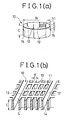
- a resistance-adjusted type heater comprising a honeycomb structure 10 having a large number of passages 11 and a predetermined number of slits 12 which serve as the resistance adjusting means, as shown in Figs. 1(a) and 1(b)
- a catalytic converter comprising the above-described resistance-adjusted type heater and a main catalyst may be operated in the manner described below when it is used to control automotive exhaust emissions.
- the heater is energized at a current density of 5/Amm2 or above for at least sixty seconds after the engine is started, to heat the low-temperature exhaust gas quickly at the beginning of the operation of an engine. If the current density is below 5 A/mm2, the heater must be preheated before the engine is started to obtain desired exhaust gas conversion characteristics. Therefore, this is not practical.
- the heater is energized at a current density of 5 A/mm2 or above until it is heated to a temperature at which any catalyst carried on the heater and the main catalyst are activated (between 300 and 400°C). Thereafter, the level of power supplied to the heater is reduced and the heater is successively energized at a reduced power level. Reduction in the power level is achieved either by turning the heater on/off or by energizing the heater at a current density which is below 5 A/mm2.
- Energization of the heater substantially concurrently with the operation of the engine may be either energization of the heater concurrently with the operation of the engine or energization about several seconds, e.g., five seconds before the engine starts.
- the heater is energized at a predetermined power level or above and thereby heated substantially concurrently with the operation of an engine.
- an oxidizing gas is introduced into the catalytic converter.
- the temperature of the heater exceeds a value at which a main catalyst of the catalytic converter or light-off catalyst carried on the heater functions, the power level is reduced by an output adjuster and supply of the oxidizing gas is suspended.
- the low-temperature exhaust gas can be quickly heated to a temperature at which the catalyst starts functioning or above at the initial stage of the operation of an engine when the emissions of a vehicle is a maximum, increase in the exhaust gas conversion can be achieved. Furthermore, since the power level is reduced immediately after the desired temperature is reached, i.e., immediately after the catalyst is ignited, an efficient operation of the catalyst is ignited, an efficient operation of the catalytic converter is possible.
- the heater is energized at a power level of 1.5 kW or above, more preferably, at 3kW or above, per unit flow rate of exhaust gas (m3/minute) and thereby heated substantially concurrently with the operation of the engine.
- the heater is heated to about 400°C within ten seconds.
- 400°C is attained in five seconds.
- a battery of 24V is usually used.
- the battery is preferably used together with a capacitor to obtain a temporary large current.
- the exhaust gas at the beginning of the operation of the engine is rich (reducing atmosphere)
- introduction of the oxidizing gas is necessary for the conversion of CO and HC into CO2 and water.
- suitable oxidizing gas include air, oxygen and ozone. From the practical point of view, however, introduction of air is simple and thus preferred.
- the oxidizing gas is introduced, the amount of oxidizing gas is controlled in accordance with the engine speed by a mass flow sensor. In a practical operation, the amount of, for example, secondary air introduced is controlled such that the oxidation-reduction index given by the following expression will be held between 0 ⁇ .7 and 1.1, more preferable, between 0 ⁇ .8 and 1.0 ⁇ .
- the heater is heated generally to a temperature at which the main catalyst of the catalytic converter or the light-off catalyst carried on the heater is activated or above, i.e., 30 ⁇ 0 ⁇ °C or above.
- the power level is reduced by an output adjuster.
- reduction in the power level is achieved by performing on-off control of the battery of 24V or 12V (by reducing the power level per unit time) or by performing inverter control.
- the time when the operation of reducing the power level begins varies depending on the level of power supplied, as stated above, since the temperature of the heater reaches 40 ⁇ 0 ⁇ °C within five or ten seconds, reduction in the power level is conducted five or ten seconds later from the energization of the heater.
- Energization of the heater is suspended generally in sixty seconds or less.
- the preferred heater employed in the present techniques is one having a resistance adjusting means. Such a heater is energized at a preferred current density of 5 A/mm2 or above. Energization of the heater at a current density of 5 A/mm2 or above increases the rate at which the temperature of the heater rises, and thus allows the temperature of the heater to reach 30 ⁇ 0 ⁇ °C or above within ten seconds. This in turn enables the main catalyst or the light-off catalyst carried on the heater to be activated effectively. More preferably, the heater is energized at a current density of 8 A/mm2 or above. However, with too high a current density, a large amount of power is required and the catalyst on the heater is heated too high. From the viewpoint of durability of the catalyst, energization at no more than 30 ⁇ A/mm2 is therefore preferred.
- the basic body of the heater prefferably has a honeycomb structure.
- any material, ceramic or metal, capable of generating heat when energized can be used as the material of the honeycomb structure which is a basic body of the present invention
- the use of metal enhances the mechanical strength and is thus preferred.
- metals include stainless steel and materials having compositions of Fe-Cr-Al, Fe-Cr, Fe-Al, Fe-Ni, W-Co, and Ni-Cr.
- Fe-Cr-Al, Fe-Cr and Fe-Al are preferred because of low cost and high resistance to heat, oxidation and corrosion.
- the honeycomb structure employed in the present invention may be porous or non-porous.
- a porous honeycomb structure is preferred because a catalyst layer can be closely adhered to such a honeycomb structure, and hardly peels off the honeycomb structure even when a difference in the thermal expansion between the honeycomb structure and the catalyst exists.
- the metal honeycomb structure may be prepared in the manner described below.
- Fe powder, Al powder and Cr powder, or alternatively powders of alloys of these metals are mixed to prepare a metal powder mixture having a desired composition.
- the metal powder mixture is blended into an organic binder, such as methyl cellulose or polyvinylalcohol, and water to produce a readily formable mixture. That mixture is then formed into a shape of a desired honeycomb configuration by extrusion.
- the formed honeycomb body is fired in a non-oxidizing atmosphere at a temperature ranging between 10 ⁇ 0 ⁇ 0 ⁇ and 1450 ⁇ °C.
- the organic binder is decomposed and thereby removed with the aid of Fe or the like, which acts as a catalyst.
- a good sintered body (a honeycomb structure) can therefore be obtained.
- a heat-resistant metal oxide layer is then formed on the surface of the cell walls and the surface of the pores of the obtained honeycomb structure.
- a resistance adjusting arrangement of a desired form is preferably provided on the obtained honeycomb structure between the electrodes thereof, which will be described later.
- the resistance adjusting arrangement provided on the honeycomb structure may take on any of the following forms:
- formation of a slit or slits according to No.(1) is more preferable because it can easily control a heated portion.
- Electrodes are provided generally on the outer peripheral portion of or inside of the thus-obtained metal honeycomb structure by welding or brazing to manufacture a honeycomb heater.
- Electrodes is used in this application to refer to any terminal through which a voltage is applied to the heater.
- the electrodes therefore include the direct bonding of the outer peripheral portion of the heater to a can body and terminals for grounding.
- the resistance thereof will be preferably held between 0 ⁇ .0 ⁇ 0 ⁇ 1 ⁇ and 0 ⁇ .5 ⁇ .
- a catalyst is placed on the surface of the thus-obtained metal honeycomb structure so as to allow heat to be generated due to reaction (oxidation) of the exhaust gas.
- the catalyst supported on the surface of the metal honeycomb structure is made of a carrier having a high surface area and a catalyst activating material supported on the carrier.
- Typical examples of the carriers having a high surface area include ⁇ -Al2O3, TiO2, SiO2-Al2O3 and perovskite.
- Examples of the catalytic activating materials include noble metals, such as Pt, Pd and Rh, and base metals, such as Cu, Ni, Cr and Co.
- the preferred catalyst comprises one in which from 10 ⁇ to 10 ⁇ 0 ⁇ g/ft3 of Pt and/or Pd is loaded on the carrier made of ⁇ -Al2O3.
- the honeycomb structure may have any honeycomb configuration
- the cell wall thickness (rib thickness) of the preferred honeycomb structure ranges between 75 and 500 ⁇ m. Below 75 ⁇ m, the structure deteriorates in strength and in the life of the heater. Above 500 ⁇ m, the pressure loss is great and a large amount of power is required to raise the temperature thereof. The most preferable range is between 100 and 300 ⁇ m.
- the honeycomb structure has a cell density ranging from 15.5 to 62 cells/cm2 (100 to 400 cells/in2). More specifically, a cell density of 15.5 cells/cm2 (100 cells/in2) or above is preferred taking into account the heat transfer area for heating gas flow in passages formed in the honeycomb structure and the catalyst surface area when the catalyst is carried on the honeycomb structure. Above 62 cells/cm2 (400 cells/in2) formation of the slits is difficult, and short-circuiting readily occurs due to the insufficient distance between the ribs which form a slit.
- the open frontal area of the honeycomb structure is preferably between 50 and 85% from the viewpoints of the pressure loss and the strength.
- the preferred length of the heater is about 1/20 ⁇ to 1/3 of the length of the main catalyst.
- Slits are preferred to control the heating portion of the heater.
- the heater In the case of a heater designed for use in automotive exhaust gas control, it is preferable for the heater to be heated relatively uniformly, and the slits are therefore formed such that the distance between the slit and the outer wall is larger than that between the adjacent slits.
- a large number of slits formed in the heater increases the overall heating length of the heater and is therefore preferable. However, it also increases the resistance of the heater. This may result in reduction in a current density to below 5 A/mm2 in the case where the voltage applied to the heater is fixed. So, the number of slits formed in the heater is determined such that it achieves a current density of 5 A/mm2 or above.
- honeycomb structure is employed in this application to refer to an integral body having a large number of passages partitioned by cell walls.
- the passages may have any cross-sectional form (cell shape), e.g., a circular, polygonal or corrugated form.
- Fig. 1(a) is a perspective view of an example of a resistance-adjusting type heater.
- Fig. 1(b) is an enlarged perspective view of the essential parts of the heater of Fig. 1(a) which comprises a honeycomb structure 10 ⁇ having a large number of passages 11 and a plurality of slits 12 which serve as the resistance adjusting means, the outer wall of the honeycomb structure 10 ⁇ being provided with two electrodes 15.
- a reference numeral 13 denotes a cell wall (rib); 14, the cross-section of the rib; S, the cross-sectional area of the section 14 of all the ribs present between the adjacent slits; B, the diameter of a heater; C, the length of a heater; and D, the length of a slit.
- the obtained mixture was then blended into an organic binder (methyl cellulose), an antioxidant (oleic acid) and water to produce a readily formable body.
- the obtained body was then formed into honeycomb bodies having various rib thicknesses and various numbers of square cells (shown in Table 1) by extrusion.
- the formed honeycomb structures were dried, sintered in an atmosphere of H2 at 130 ⁇ 0 ⁇ °C, and then subjected to heat treatment at 10 ⁇ 0 ⁇ 0 ⁇ °C in the oxidizing atmosphere to form a heat-resistant metal oxide layer.
- the porosity of the obtained honeycomb structures was 22% by volume and the average pore diameter thereof was 5 ⁇ m.
- honeycomb structures 10 ⁇ having an outer diameter of 90 ⁇ mm ⁇ were processed such that they had various heater lengths C shown in Table 1. Thereafter, a predetermined number of slits 12, having a length ranging from 50 ⁇ to 70 ⁇ mm, were formed in the individual honeycomb structure 10 ⁇ . Thereafter, two electrodes 15 were provided on the outer wall of the individual resistance adjusting type heater obtained, and then a heat-resistant inorganic adhesive of zirconia was filled in the outer peripheral portion of each slit 12 to form an insulating portion, as shown in Fig. 1(a).
- the individual heater was energized by a power source comprising a single 12V battery for use in a automobile, or two such batteries which were connected in series, while air was supplied thereto at a rate of 0 ⁇ .7 m3/min. At that time, the temperature of the heater was measured. Table 1 and Fig. 2 respectively show the time required for each heater to be heated to temperatures of 20 ⁇ 0 ⁇ °C, 30 ⁇ 0 ⁇ °C and 40 ⁇ 0 ⁇ °C.
- the preferred heaters thus provide a current density of at least 5 A/mm2 at 24V, or at 12V.
- the heaters which ensure a current density of 5 A/mm2 or above can be heated to 30 ⁇ 0 ⁇ °C within ten seconds.
- the heater No. 5 and a heater No. 11 which comprised of the heater No. 5 with a catalyst of CeO2 - ⁇ -Al2O3 (in which Pt and Pd were respectively present in an amount of 20 ⁇ g/ft3) carried (coated) thereon were respectively prepared.
- Each of the heaters Nos. 5 and 11 was disposed in advance of (upstream of) a three-way catalyst (whose rib thickness was 6 mil and whose cell density was 62 cells/cm2 (400 cells/in2)) which was a main monolithic catalyst having an outer diameter of 90 mm ⁇ and a length of 100mm.
- the examples which ensured a current density of 5 A/mm2 or above exhibited more excellent exhaust gas conversion than the comparative examples which ensured a current density of no more than 5 A/mm2.
- the catalyst of heater No. 2 was activated to the highest degree. Heater No. 2 was turned off after it had been energized for about one and a half minutes, because it started heat generation by ignition of the catalyst carried on the heater.
- the catalytic converter employed in this Example comprised a three-way catalyst (whose rib thickness was 5 mil and whose cell density was 62 cells/cm2 (400 cells/in2)), having an outer diameter of 90 mm ⁇ and a length of 100 mm, which served as a main monolithic catalyst, and a heater disposed in advance of (upstream of) the three-way catalyst.
- the heater employed in the above catalytic converter was manufactured in the manner described below.
- the obtained mixture was then blended into an organic binder (methyl cellulose), an antioxidant (oleic acid) and water to produce a readily formable body.
- the obtained body was then formed into honeycomb bodies having various rib thicknesses and various numbers of square cells shown in Table 3 by extrusion.
- the formed honeycomb structures were dried, sintered in an atmosphere of H2 at 130 ⁇ 0 ⁇ °C, and then subjected to heat treatment at 10 ⁇ 0 ⁇ 0 ⁇ °C in the atmosphere.
- the porosity of the obtained honeycomb structures was 22 % and the average pore diameter thereof was 5 ⁇ m.
- the obtained honeycomb structures 10 ⁇ having an outer diameter of 90 ⁇ mm ⁇ were processed such that they had various heater lengths shown in Table 3. Thereafter, a predetermined number of slits 12, having a length ranging from 50 ⁇ to 70 ⁇ mm, were formed in the individual honeycomb structure 10 ⁇ . Thereafter, two electrodes 15 were provided on the outer wall of the individual resistance adjusting type heater obtained, and then a heat-resistant inorganic adhesive of zirconia was filled in the outer peripheral portion of each slit 12 to form an insulating portion.
- a catalyst of CeO2- ⁇ -Al2O3 in which Pt and Pd were respectively present in an amount of 20 ⁇ g was placed on each of heater Nos. 12 and 13.
- the individual heater was energized using a battery of 24 V or 12 V. Energization started concurrently with the introduction of the engine exhaust gas. When the temperature of the heater reached 450 ⁇ °C, on-off control began. For reference, test was also conducted in which the heater was energized for thirty seconds before the exhaust gas was introduced.
- Table 4 shows the results of the test.
- the resistance adjusting means is formed on the heater and catalytic converter such that it ensures a current density of 5 A/mm2 or above, or since the catalytic converter is operated such that it ensures a current density of 5 A/mm2 or above, low-temperature automotive exhaust emissions at the beginning of the operation of an engine or the like can be quickly heated, and a high exhaust gas conversion can thus be achieved.
- the temperature of a heater and that of a main catalyst incorporated in the catalytic converter are raised quickly at the initial stage of the operation of an engine to activate the catalysts and thereby achieve increase in the exhaust gas conversion.
- the level of power is reduced after the desired temperature has been reached. In consequence, the catalytic converter can be operated efficiently an economically.
Landscapes
- Engineering & Computer Science (AREA)
- Chemical & Material Sciences (AREA)
- Chemical Kinetics & Catalysis (AREA)
- Combustion & Propulsion (AREA)
- Health & Medical Sciences (AREA)
- Mechanical Engineering (AREA)
- Toxicology (AREA)
- General Engineering & Computer Science (AREA)
- Biomedical Technology (AREA)
- Environmental & Geological Engineering (AREA)
- Analytical Chemistry (AREA)
- General Chemical & Material Sciences (AREA)
- Oil, Petroleum & Natural Gas (AREA)
- Exhaust Gas After Treatment (AREA)
- Catalysts (AREA)
Applications Claiming Priority (7)
| Application Number | Priority Date | Filing Date | Title |
|---|---|---|---|
| JP176942/90 | 1990-07-04 | ||
| JP17694390 | 1990-07-04 | ||
| JP176943/90 | 1990-07-04 | ||
| JP17694290 | 1990-07-04 | ||
| JP2176942A JP3034913B2 (ja) | 1990-07-04 | 1990-07-04 | 触媒コンバーターの操作方法 |
| JP2176943A JP2843426B2 (ja) | 1990-07-04 | 1990-07-04 | 触媒コンバーターの操作方法 |
| EP91305927A EP0465184B1 (de) | 1990-07-04 | 1991-07-01 | Heizelement mit einstellbarem Widerstand, katalytischer Konverter und Verfahren zur Steuerung der Abgasemissionen |
Related Parent Applications (2)
| Application Number | Title | Priority Date | Filing Date |
|---|---|---|---|
| EP91305927A Division EP0465184B1 (de) | 1990-07-04 | 1991-07-01 | Heizelement mit einstellbarem Widerstand, katalytischer Konverter und Verfahren zur Steuerung der Abgasemissionen |
| EP91305927.5 Division | 1991-07-01 |
Publications (3)
| Publication Number | Publication Date |
|---|---|
| EP0717178A2 true EP0717178A2 (de) | 1996-06-19 |
| EP0717178A3 EP0717178A3 (de) | 1996-07-17 |
| EP0717178B1 EP0717178B1 (de) | 2001-04-04 |
Family
ID=26497663
Family Applications (2)
| Application Number | Title | Priority Date | Filing Date |
|---|---|---|---|
| EP95117896A Revoked EP0717178B1 (de) | 1990-07-04 | 1991-07-01 | Betrieb eines katalytischen Konverters |
| EP91305927A Expired - Lifetime EP0465184B1 (de) | 1990-07-04 | 1991-07-01 | Heizelement mit einstellbarem Widerstand, katalytischer Konverter und Verfahren zur Steuerung der Abgasemissionen |
Family Applications After (1)
| Application Number | Title | Priority Date | Filing Date |
|---|---|---|---|
| EP91305927A Expired - Lifetime EP0465184B1 (de) | 1990-07-04 | 1991-07-01 | Heizelement mit einstellbarem Widerstand, katalytischer Konverter und Verfahren zur Steuerung der Abgasemissionen |
Country Status (5)
| Country | Link |
|---|---|
| EP (2) | EP0717178B1 (de) |
| AU (2) | AU651352B2 (de) |
| CA (1) | CA2045812C (de) |
| DE (2) | DE69132576T2 (de) |
| ES (1) | ES2157282T3 (de) |
Families Citing this family (13)
| Publication number | Priority date | Publication date | Assignee | Title |
|---|---|---|---|---|
| JP3196044B2 (ja) * | 1992-09-30 | 2001-08-06 | 株式会社日本ケミカル・プラント・コンサルタント | 気体加熱装置 |
| JP3506747B2 (ja) * | 1992-12-15 | 2004-03-15 | 日本碍子株式会社 | ハニカムヒーター |
| DE4300477A1 (de) * | 1993-01-11 | 1994-07-14 | Emitec Emissionstechnologie | Extrudierter Wabenkörper aus keramischem und/oder metallischem Material mit erhöhter Flexibilität |
| US5866230A (en) * | 1993-01-11 | 1999-02-02 | Emitec Gesellschaft Fuer Emissionstechnologie Gmbh | Extruded honeycomb body of ceramic and/or metallic material with increased flexibility |
| DE4341380A1 (de) * | 1993-12-04 | 1995-06-14 | Degussa | Verfahren zur Beschleunigung der Aufheizung von Feststoffkatalysatoren durch Zufuhr von Hilfsenergie |
| JP3210508B2 (ja) * | 1993-12-14 | 2001-09-17 | 日本碍子株式会社 | ハニカムヒーター |
| JPH07163888A (ja) * | 1993-12-14 | 1995-06-27 | Ngk Insulators Ltd | ハニカムヒーター |
| JPH07166846A (ja) * | 1993-12-14 | 1995-06-27 | Ngk Insulators Ltd | ハニカムヒーター |
| EP0718480A1 (de) | 1994-11-25 | 1996-06-26 | Société Anonyme dite: REGIE NATIONALE DES USINES RENAULT | Abgasanlage für Brennkraftmaschine |
| JP3345222B2 (ja) * | 1995-07-21 | 2002-11-18 | 日本碍子株式会社 | 通電発熱用ハニカム体およびハニカムユニット |
| JPH09103684A (ja) * | 1995-10-13 | 1997-04-22 | Ngk Insulators Ltd | 並列発熱型ハニカムヒーター |
| FR2771778B1 (fr) | 1997-11-28 | 2000-01-14 | Renault | Procede de commande d'un moteur a injection directe et allumage commande |
| WO2022115349A1 (en) * | 2020-11-30 | 2022-06-02 | Corning Incorporated | Electrically powered catalyst heater for fluid treatment systems |
Citations (1)
| Publication number | Priority date | Publication date | Assignee | Title |
|---|---|---|---|---|
| JPS6367609U (de) | 1986-10-23 | 1988-05-07 |
Family Cites Families (10)
| Publication number | Priority date | Publication date | Assignee | Title |
|---|---|---|---|---|
| JPS4847479A (de) * | 1971-10-20 | 1973-07-05 | ||
| DE2333092A1 (de) * | 1973-06-29 | 1975-01-16 | Volkswagenwerk Ag | Abgasreinigungsanlage |
| US3956614A (en) * | 1975-04-21 | 1976-05-11 | Universal Oil Products Company | Electric current distribution means for a ceramic type of electrical resistance heater element |
| US4264888A (en) * | 1979-05-04 | 1981-04-28 | Texas Instruments Incorporated | Multipassage resistor and method of making |
| DE3661978D1 (en) * | 1985-03-14 | 1989-03-02 | Siemens Ag | Heating element for heating streaming, especially gaseous media |
| US4758272A (en) * | 1987-05-27 | 1988-07-19 | Corning Glass Works | Porous metal bodies |
| DE8816514U1 (de) * | 1988-04-25 | 1989-10-26 | Emitec Gesellschaft für Emissionstechnologie mbH, 5204 Lohmar | Elektrisch beheizbarer Katalysator-Trägerkörper |
| US4976929A (en) * | 1988-05-20 | 1990-12-11 | W. R. Grace & Co.-Conn. | Electrically heated catalytic converter |
| CA2040289C (en) * | 1990-04-12 | 1998-09-29 | Hiroshige Mizuno | Resistance adjusting type heater and catalytic converter |
| JP2931362B2 (ja) * | 1990-04-12 | 1999-08-09 | 日本碍子株式会社 | 抵抗調節型ヒーター及び触媒コンバーター |
-
1991
- 1991-06-27 CA CA002045812A patent/CA2045812C/en not_active Expired - Fee Related
- 1991-07-01 DE DE69132576T patent/DE69132576T2/de not_active Revoked
- 1991-07-01 EP EP95117896A patent/EP0717178B1/de not_active Revoked
- 1991-07-01 EP EP91305927A patent/EP0465184B1/de not_active Expired - Lifetime
- 1991-07-01 DE DE69122321T patent/DE69122321T2/de not_active Expired - Fee Related
- 1991-07-01 ES ES95117896T patent/ES2157282T3/es not_active Expired - Lifetime
- 1991-07-03 AU AU80177/91A patent/AU651352B2/en not_active Ceased
-
1994
- 1994-06-07 AU AU64617/94A patent/AU663653B2/en not_active Ceased
Patent Citations (1)
| Publication number | Priority date | Publication date | Assignee | Title |
|---|---|---|---|---|
| JPS6367609U (de) | 1986-10-23 | 1988-05-07 |
Also Published As
| Publication number | Publication date |
|---|---|
| DE69122321D1 (de) | 1996-10-31 |
| DE69132576T2 (de) | 2001-10-18 |
| EP0465184A1 (de) | 1992-01-08 |
| AU6461794A (en) | 1994-08-04 |
| CA2045812A1 (en) | 1992-01-05 |
| EP0717178B1 (de) | 2001-04-04 |
| AU8017791A (en) | 1992-01-09 |
| AU663653B2 (en) | 1995-10-12 |
| AU651352B2 (en) | 1994-07-21 |
| ES2157282T3 (es) | 2001-08-16 |
| CA2045812C (en) | 1994-11-01 |
| DE69122321T2 (de) | 1997-03-06 |
| DE69132576D1 (de) | 2001-05-10 |
| EP0717178A3 (de) | 1996-07-17 |
| EP0465184B1 (de) | 1996-09-25 |
Similar Documents
| Publication | Publication Date | Title |
|---|---|---|
| JP2919987B2 (ja) | 抵抗調節型ヒーター | |
| US5063029A (en) | Resistance adjusting type heater and catalytic converter | |
| US5234668A (en) | Catalytic converter for use in automotive exhaust emissions control | |
| JP3001281B2 (ja) | ハニカムモノリスヒータ | |
| US5200154A (en) | Honeycomb heater having integrally formed electrodes and/or integrally sintered electrodes and method of manufacturing such honeycomb heater | |
| US5288975A (en) | Resistance adjusting type heater | |
| JP3040510B2 (ja) | ハニカムヒーター | |
| US5264186A (en) | Catalytic converter for use in controlling automotive exhaust emissions | |
| EP0452125B1 (de) | Heizgerät und Katalysatoreinrichtung | |
| US5229079A (en) | Catalytic converter for use in automotive exhaust emission control | |
| EP0717178A2 (de) | Betrieb eines katalytischen Konverters | |
| US5229080A (en) | Resistance adjusting type heater and catalytic converter | |
| US5266278A (en) | Honeycomb heater having integrally formed electrodes and/or integrally sintered electrodes and method of manufacturing such honeycomb heater | |
| JP2915586B2 (ja) | 抵抗調節型ヒーター | |
| US5680503A (en) | Honeycomb heater having a portion that is locally quickly heated | |
| JP3345222B2 (ja) | 通電発熱用ハニカム体およびハニカムユニット | |
| JP3058995B2 (ja) | ハニカムヒーター | |
| US5194229A (en) | Resistance heater, catalytic converter and method of operating catalytic converter | |
| EP0465183B1 (de) | Katalytischer Konverter mit Widerstand-Heizelement | |
| JP2843426B2 (ja) | 触媒コンバーターの操作方法 | |
| JP3058992B2 (ja) | 多段ハニカムヒーター | |
| JPH10325314A (ja) | 抵抗調節型ヒーター及び触媒コンバーター | |
| JP2818477B2 (ja) | 自動車排ガス浄化用触媒コンバーター | |
| JP3058991B2 (ja) | 多段ハニカムヒーターおよびその運転方法 | |
| JP2863330B2 (ja) | 抵抗調節型ヒーター |
Legal Events
| Date | Code | Title | Description |
|---|---|---|---|
| PUAI | Public reference made under article 153(3) epc to a published international application that has entered the european phase |
Free format text: ORIGINAL CODE: 0009012 |
|
| PUAL | Search report despatched |
Free format text: ORIGINAL CODE: 0009013 |
|
| AC | Divisional application: reference to earlier application |
Ref document number: 465184 Country of ref document: EP |
|
| AK | Designated contracting states |
Kind code of ref document: A2 Designated state(s): BE DE ES FR GB IT SE |
|
| AK | Designated contracting states |
Kind code of ref document: A3 Designated state(s): BE DE ES FR GB IT SE |
|
| 17P | Request for examination filed |
Effective date: 19960924 |
|
| 17Q | First examination report despatched |
Effective date: 19990222 |
|
| GRAG | Despatch of communication of intention to grant |
Free format text: ORIGINAL CODE: EPIDOS AGRA |
|
| GRAG | Despatch of communication of intention to grant |
Free format text: ORIGINAL CODE: EPIDOS AGRA |
|
| GRAH | Despatch of communication of intention to grant a patent |
Free format text: ORIGINAL CODE: EPIDOS IGRA |
|
| GRAH | Despatch of communication of intention to grant a patent |
Free format text: ORIGINAL CODE: EPIDOS IGRA |
|
| GRAA | (expected) grant |
Free format text: ORIGINAL CODE: 0009210 |
|
| AC | Divisional application: reference to earlier application |
Ref document number: 465184 Country of ref document: EP |
|
| AK | Designated contracting states |
Kind code of ref document: B1 Designated state(s): BE DE ES FR GB IT SE |
|
| REF | Corresponds to: |
Ref document number: 69132576 Country of ref document: DE Date of ref document: 20010510 |
|
| ITF | It: translation for a ep patent filed | ||
| REG | Reference to a national code |
Ref country code: ES Ref legal event code: FG2A Ref document number: 2157282 Country of ref document: ES Kind code of ref document: T3 |
|
| ET | Fr: translation filed | ||
| REG | Reference to a national code |
Ref country code: GB Ref legal event code: IF02 |
|
| PLBQ | Unpublished change to opponent data |
Free format text: ORIGINAL CODE: EPIDOS OPPO |
|
| PLAV | Examination of admissibility of opposition |
Free format text: ORIGINAL CODE: EPIDOS OPEX |
|
| PLBI | Opposition filed |
Free format text: ORIGINAL CODE: 0009260 |
|
| PLAV | Examination of admissibility of opposition |
Free format text: ORIGINAL CODE: EPIDOS OPEX |
|
| PLBF | Reply of patent proprietor to notice(s) of opposition |
Free format text: ORIGINAL CODE: EPIDOS OBSO |
|
| 26 | Opposition filed |
Opponent name: EMITEC GESELLSCHAFT FUER EMISSIONSTECHNOLOGIE MBH Effective date: 20020103 |
|
| PLBF | Reply of patent proprietor to notice(s) of opposition |
Free format text: ORIGINAL CODE: EPIDOS OBSO |
|
| PLBF | Reply of patent proprietor to notice(s) of opposition |
Free format text: ORIGINAL CODE: EPIDOS OBSO |
|
| PLBF | Reply of patent proprietor to notice(s) of opposition |
Free format text: ORIGINAL CODE: EPIDOS OBSO |
|
| PGFP | Annual fee paid to national office [announced via postgrant information from national office to epo] |
Ref country code: ES Payment date: 20030507 Year of fee payment: 13 |
|
| PGFP | Annual fee paid to national office [announced via postgrant information from national office to epo] |
Ref country code: SE Payment date: 20030723 Year of fee payment: 13 Ref country code: BE Payment date: 20030723 Year of fee payment: 13 |
|
| PGFP | Annual fee paid to national office [announced via postgrant information from national office to epo] |
Ref country code: GB Payment date: 20040621 Year of fee payment: 14 |
|
| PG25 | Lapsed in a contracting state [announced via postgrant information from national office to epo] |
Ref country code: SE Free format text: LAPSE BECAUSE OF NON-PAYMENT OF DUE FEES Effective date: 20040702 Ref country code: ES Free format text: LAPSE BECAUSE OF NON-PAYMENT OF DUE FEES Effective date: 20040702 |
|
| PGFP | Annual fee paid to national office [announced via postgrant information from national office to epo] |
Ref country code: FR Payment date: 20040723 Year of fee payment: 14 |
|
| PG25 | Lapsed in a contracting state [announced via postgrant information from national office to epo] |
Ref country code: BE Free format text: LAPSE BECAUSE OF NON-PAYMENT OF DUE FEES Effective date: 20040731 |
|
| PLCK | Communication despatched that opposition was rejected |
Free format text: ORIGINAL CODE: EPIDOSNREJ1 |
|
| APBP | Date of receipt of notice of appeal recorded |
Free format text: ORIGINAL CODE: EPIDOSNNOA2O |
|
| APAA | Appeal reference recorded |
Free format text: ORIGINAL CODE: EPIDOS REFN |
|
| BERE | Be: lapsed |
Owner name: *NGK INSULATORS LTD Effective date: 20040731 |
|
| APBQ | Date of receipt of statement of grounds of appeal recorded |
Free format text: ORIGINAL CODE: EPIDOSNNOA3O |
|
| EUG | Se: european patent has lapsed | ||
| PG25 | Lapsed in a contracting state [announced via postgrant information from national office to epo] |
Ref country code: IT Free format text: LAPSE BECAUSE OF NON-PAYMENT OF DUE FEES;WARNING: LAPSES OF ITALIAN PATENTS WITH EFFECTIVE DATE BEFORE 2007 MAY HAVE OCCURRED AT ANY TIME BEFORE 2007. THE CORRECT EFFECTIVE DATE MAY BE DIFFERENT FROM THE ONE RECORDED. Effective date: 20050701 Ref country code: GB Free format text: LAPSE BECAUSE OF NON-PAYMENT OF DUE FEES Effective date: 20050701 |
|
| APAH | Appeal reference modified |
Free format text: ORIGINAL CODE: EPIDOSCREFNO |
|
| REG | Reference to a national code |
Ref country code: ES Ref legal event code: FD2A Effective date: 20040702 |
|
| GBPC | Gb: european patent ceased through non-payment of renewal fee |
Effective date: 20050701 |
|
| PG25 | Lapsed in a contracting state [announced via postgrant information from national office to epo] |
Ref country code: FR Free format text: LAPSE BECAUSE OF NON-PAYMENT OF DUE FEES Effective date: 20060331 |
|
| REG | Reference to a national code |
Ref country code: FR Ref legal event code: ST Effective date: 20060331 |
|
| PGFP | Annual fee paid to national office [announced via postgrant information from national office to epo] |
Ref country code: DE Payment date: 20070731 Year of fee payment: 17 |
|
| APBU | Appeal procedure closed |
Free format text: ORIGINAL CODE: EPIDOSNNOA9O |
|
| BERE | Be: lapsed |
Owner name: *NGK INSULATORS LTD Effective date: 20040731 |
|
| RDAF | Communication despatched that patent is revoked |
Free format text: ORIGINAL CODE: EPIDOSNREV1 |
|
| RDAG | Patent revoked |
Free format text: ORIGINAL CODE: 0009271 |
|
| STAA | Information on the status of an ep patent application or granted ep patent |
Free format text: STATUS: PATENT REVOKED |
|
| 27W | Patent revoked |
Effective date: 20070906 |