EP0717329A2 - Circuit disposé pour la mesure d'une intervalle de temps - Google Patents
Circuit disposé pour la mesure d'une intervalle de temps Download PDFInfo
- Publication number
- EP0717329A2 EP0717329A2 EP95308546A EP95308546A EP0717329A2 EP 0717329 A2 EP0717329 A2 EP 0717329A2 EP 95308546 A EP95308546 A EP 95308546A EP 95308546 A EP95308546 A EP 95308546A EP 0717329 A2 EP0717329 A2 EP 0717329A2
- Authority
- EP
- European Patent Office
- Prior art keywords
- ring oscillator
- output
- circuit arrangement
- signal
- time interval
- Prior art date
- Legal status (The legal status is an assumption and is not a legal conclusion. Google has not performed a legal analysis and makes no representation as to the accuracy of the status listed.)
- Granted
Links
Images

Classifications
-
- G—PHYSICS
- G04—HOROLOGY
- G04F—TIME-INTERVAL MEASURING
- G04F10/00—Apparatus for measuring unknown time intervals by electric means
- G04F10/04—Apparatus for measuring unknown time intervals by electric means by counting pulses or half-cycles of an AC
Definitions
- the present invention relates to circuit arrangements for measuring time intervals, and in particular for measuring time intervals down to the order of hundreds of picoseconds.
- Circuit arrangements are known, for example from European published patent applications Nos. EP - 300,757 and EP - 508,232, in which ring oscillators comprising tapped delay lines or chains of bistable stages are enabled at the commencement of a time interval to be measured, indicated by the leading edge of a pulse signal of a duration representing the time interval, the number of complete cycles of operation and the phase or state of the ring oscillator at the end of the time interval, indicated by the trailing edge of the pulse signal, being taken as the measure of the time interval.
- Such an arrangement can be calibrated by using one or more reference pulses of known duration.
- the state of the ring oscillator may for example be latched into a plurality of latches, one for each tap on the delay line or for each of the chain of stages of the oscillator, at the end of the pulse signal, while the number of cycles of operation may be registered in a high frequency counter counting pulses from the last tap or stage of the ring oscillator.
- the oscillator may have, say, ten taps or stages.
- a circuit arrangement for measuring a time interval which may be defined by transitions between logic signal levels of an input signal to said arrangement, one of which logic signal levels constitutes an enabling signal level for said circuit arrangement, including a ring oscillator comprising a plurality of stages, a like plurality of latches associated one with each of said stages, and counter means for counting complete cycles of said ring oscillator, there are provided means responsive to the logic signal level of said input signal and to output signal pulses from said ring oscillator to apply said output pulses to said counter means and to give an indication whether a transition in said input signal from said enabling signal level occurs before or after a predetermined transition in said output signal pulses from said ring oscillator.
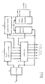
- the circuit arrangement comprises a ring oscillator 1 comprising ten stages (not shown) through which a binary value may propagate with a delay per stage of, say, one hundred picoseconds, such that while the oscillator 1 is enabled it provides an output pulse to a high frequency counter 2 by way of a synchronizer circuit 3 every nanosecond.
- An input pulse signal the period of which represents a time interval to be measured is applied by way of an input terminal 4 to a control circuit 5, which at the commencement or leading edge of the input pulse signal applies an enable logic signal level to the synchronizer circuit 3 and to an error detecting circuit 6, and applies the inverse of that enable logic signal level to a set of latches 7 associated with respective stages of the ring oscillator 1.
- the ring oscillator 1 is initiallised and set to operate.
- the enable logic signal level is removed from the synchronizer 3 and the error detecting circuit 6, and the state of the ring oscillator 1 is arranged to be latched into the latches 7.
- a "coarse" value for the length of the time interval to be measured is then available from the count registered by the counter 2, while a "fine” value of a fraction of a ring oscillator period may be derived from the latches 7, for example by way of a look-up calibration table (not shown).
- the synchronizer circuit 3 comprises two D-type flip flops 8, through which the enable logic signal level is clocked by output pulses from the ring oscillator 1, and an AND gate 9 the output of which is connected to clock the first stage of the counter 2 and to the clock input of a D-type flip flop 10 in the error detecting circuit 6.
- the enable logic signal level is also applied to a select circuit 11 of the error detecting circuit 6.
- the select circuit 11 connects the Q output to the D input of the flip-flop 10, whereas once the enable logic signal level is removed the Q ⁇ output is connected to the D input. Because of this if only one output pulse 14 is passed to the counter 2 after the removal of the enable logic signal level, Figure 3(a), the Q output of the flip-flop 10 switches to a one-state and remains in that state whereas if two output pulses 14 are passed to the counter 2, Figure 3(b), the Q output of the flip-flop 10 switches to a one-state and back again.
- the latter form of Q output indicating that a cycle of the ring oscillator 1 has just been completed and counted by the counter 2, may be used to ensure that the state or phase of the ring oscillator 1 as indicated by the state of the latches 7 may be interpreted correctly.
Landscapes
- Engineering & Computer Science (AREA)
- Power Engineering (AREA)
- Physics & Mathematics (AREA)
- General Physics & Mathematics (AREA)
- Measurement Of Unknown Time Intervals (AREA)
- Manipulation Of Pulses (AREA)
Applications Claiming Priority (2)
| Application Number | Priority Date | Filing Date | Title |
|---|---|---|---|
| GB9425431A GB2296142B (en) | 1994-12-16 | 1994-12-16 | Circuit arrangement for measuring a time interval |
| GB9425431 | 1994-12-16 |
Publications (3)
| Publication Number | Publication Date |
|---|---|
| EP0717329A2 true EP0717329A2 (fr) | 1996-06-19 |
| EP0717329A3 EP0717329A3 (fr) | 1999-02-17 |
| EP0717329B1 EP0717329B1 (fr) | 2003-02-05 |
Family
ID=10766062
Family Applications (1)
| Application Number | Title | Priority Date | Filing Date |
|---|---|---|---|
| EP95308546A Expired - Lifetime EP0717329B1 (fr) | 1994-12-16 | 1995-11-28 | Circuit disposé pour la mesure d'une intervalle de temps |
Country Status (6)
| Country | Link |
|---|---|
| US (1) | US5684760A (fr) |
| EP (1) | EP0717329B1 (fr) |
| JP (1) | JPH08297177A (fr) |
| AT (1) | ATE232309T1 (fr) |
| DE (1) | DE69529555T2 (fr) |
| GB (1) | GB2296142B (fr) |
Cited By (3)
| Publication number | Priority date | Publication date | Assignee | Title |
|---|---|---|---|---|
| WO2003023524A1 (fr) * | 2001-09-12 | 2003-03-20 | Lockheed Martin Corporation | Circuit permettant de mesurer le moment d'arrivee d'un evenement asynchrone |
| WO2007069139A3 (fr) * | 2005-12-12 | 2008-04-17 | Nxp Bv | Circuit de compteur électrique |
| US7999593B2 (en) | 2005-12-12 | 2011-08-16 | Nxp B.V. | Electric circuit for and method of generating a clock signal |
Families Citing this family (23)
| Publication number | Priority date | Publication date | Assignee | Title |
|---|---|---|---|---|
| US5903522A (en) * | 1996-04-19 | 1999-05-11 | Oak Technology, Inc. | Free loop interval timer and modulator |
| US5793709A (en) * | 1996-04-19 | 1998-08-11 | Xli Corporation | Free loop interval timer and modulator |
| JP3175600B2 (ja) * | 1996-08-09 | 2001-06-11 | 株式会社デンソー | 時間測定装置 |
| US5903521A (en) * | 1997-07-11 | 1999-05-11 | Advanced Micro Devices, Inc. | Floating point timer |
| US6246737B1 (en) * | 1999-10-26 | 2001-06-12 | Credence Systems Corporation | Apparatus for measuring intervals between signal edges |
| US6775217B1 (en) | 2000-05-18 | 2004-08-10 | Cirrus Logic, Inc. | Multi-stage ring oscillator for providing stable delays on EFM data pulses for recording CD-R and CD-RW medium |
| US6377094B1 (en) | 2002-03-25 | 2002-04-23 | Oak Technology, Inc. | Arbitrary waveform synthesizer using a free-running ring oscillator |
| US6396312B1 (en) * | 2000-08-11 | 2002-05-28 | Agilent Technologies, Inc. | Gate transition counter |
| US6501706B1 (en) * | 2000-08-22 | 2002-12-31 | Burnell G. West | Time-to-digital converter |
| CN1802810B (zh) * | 2003-03-04 | 2010-09-22 | 阿尔特拉公司 | 时钟与数据恢复方法和装置 |
| US6901339B2 (en) * | 2003-07-29 | 2005-05-31 | Agilent Technologies, Inc. | Eye diagram analyzer correctly samples low dv/dt voltages |
| US7400555B2 (en) * | 2003-11-13 | 2008-07-15 | International Business Machines Corporation | Built in self test circuit for measuring total timing uncertainty in a digital data path |
| US7961559B2 (en) * | 2003-11-13 | 2011-06-14 | International Business Machines Corporation | Duty cycle measurement circuit for measuring and maintaining balanced clock duty cycle |
| US20070103141A1 (en) * | 2003-11-13 | 2007-05-10 | International Business Machines Corporation | Duty cycle measurment circuit for measuring and maintaining balanced clock duty cycle |
| US8422340B2 (en) * | 2008-12-08 | 2013-04-16 | General Electric Company | Methods for determining the frequency or period of a signal |
| US8324952B2 (en) | 2011-05-04 | 2012-12-04 | Phase Matrix, Inc. | Time interpolator circuit |
| JP6299516B2 (ja) * | 2014-08-05 | 2018-03-28 | 株式会社デンソー | 時間計測回路 |
| EP3224789B1 (fr) * | 2014-09-07 | 2026-02-11 | Codrut Radu Radulescu | Système de chronométrage fractionné relatif |
| JP7087517B2 (ja) | 2018-03-22 | 2022-06-21 | セイコーエプソン株式会社 | 遷移状態取得装置、時間デジタル変換器及びa/d変換回路 |
| JP7322482B2 (ja) | 2019-04-15 | 2023-08-08 | セイコーエプソン株式会社 | 時間デジタル変換器、及びa/d変換回路 |
| JP7322483B2 (ja) | 2019-04-15 | 2023-08-08 | セイコーエプソン株式会社 | 時間デジタル変換器、及びa/d変換回路 |
| JP7408981B2 (ja) | 2019-09-30 | 2024-01-09 | セイコーエプソン株式会社 | 状態遷移器、時間デジタル変換器及びa/d変換回路 |
| US11664813B2 (en) | 2019-09-30 | 2023-05-30 | Seiko Epson Corporation | Delay circuit, time to digital converter, and A/D conversion circuit |
Citations (2)
| Publication number | Priority date | Publication date | Assignee | Title |
|---|---|---|---|---|
| EP0300757A2 (fr) | 1987-07-21 | 1989-01-25 | Logic Replacement Technology Limited | Appareil de mesure de temps |
| EP0508232A2 (fr) | 1991-04-09 | 1992-10-14 | MSC MICROCOMPUTERS SYSTEMS COMPONENTS VERTRIEBS GmbH | Circuit électronique pour la mesure de périodes de temps courtes |
Family Cites Families (6)
| Publication number | Priority date | Publication date | Assignee | Title |
|---|---|---|---|---|
| US4439046A (en) * | 1982-09-07 | 1984-03-27 | Motorola Inc. | Time interpolator |
| US4433919A (en) * | 1982-09-07 | 1984-02-28 | Motorola Inc. | Differential time interpolator |
| US4516861A (en) * | 1983-10-07 | 1985-05-14 | Sperry Corporation | High resolution and high accuracy time interval generator |
| US4968902A (en) * | 1989-08-02 | 1990-11-06 | Tektronix, Inc. | Unstable data recognition circuit for dual threshold synchronous data |
| US5020038A (en) * | 1990-01-03 | 1991-05-28 | Motorola, Inc. | Antimetastable state circuit |
| US5166959A (en) * | 1991-12-19 | 1992-11-24 | Hewlett-Packard Company | Picosecond event timer |
-
1994
- 1994-12-16 GB GB9425431A patent/GB2296142B/en not_active Expired - Fee Related
-
1995
- 1995-11-28 AT AT95308546T patent/ATE232309T1/de not_active IP Right Cessation
- 1995-11-28 DE DE69529555T patent/DE69529555T2/de not_active Expired - Fee Related
- 1995-11-28 EP EP95308546A patent/EP0717329B1/fr not_active Expired - Lifetime
- 1995-12-04 US US08/566,858 patent/US5684760A/en not_active Expired - Fee Related
- 1995-12-12 JP JP7346414A patent/JPH08297177A/ja active Pending
Patent Citations (2)
| Publication number | Priority date | Publication date | Assignee | Title |
|---|---|---|---|---|
| EP0300757A2 (fr) | 1987-07-21 | 1989-01-25 | Logic Replacement Technology Limited | Appareil de mesure de temps |
| EP0508232A2 (fr) | 1991-04-09 | 1992-10-14 | MSC MICROCOMPUTERS SYSTEMS COMPONENTS VERTRIEBS GmbH | Circuit électronique pour la mesure de périodes de temps courtes |
Cited By (4)
| Publication number | Priority date | Publication date | Assignee | Title |
|---|---|---|---|---|
| WO2003023524A1 (fr) * | 2001-09-12 | 2003-03-20 | Lockheed Martin Corporation | Circuit permettant de mesurer le moment d'arrivee d'un evenement asynchrone |
| US6894953B2 (en) | 2001-09-12 | 2005-05-17 | Lockheed Martin Corporation | Circuit for measuring time of arrival of an asynchronous event |
| WO2007069139A3 (fr) * | 2005-12-12 | 2008-04-17 | Nxp Bv | Circuit de compteur électrique |
| US7999593B2 (en) | 2005-12-12 | 2011-08-16 | Nxp B.V. | Electric circuit for and method of generating a clock signal |
Also Published As
| Publication number | Publication date |
|---|---|
| JPH08297177A (ja) | 1996-11-12 |
| DE69529555D1 (de) | 2003-03-13 |
| EP0717329B1 (fr) | 2003-02-05 |
| US5684760A (en) | 1997-11-04 |
| ATE232309T1 (de) | 2003-02-15 |
| GB9425431D0 (en) | 1995-02-15 |
| GB2296142A (en) | 1996-06-19 |
| EP0717329A3 (fr) | 1999-02-17 |
| GB2296142B (en) | 1998-03-18 |
| DE69529555T2 (de) | 2003-11-20 |
Similar Documents
| Publication | Publication Date | Title |
|---|---|---|
| US5684760A (en) | Circuit arrangement for measuring a time interval | |
| US6611477B1 (en) | Built-in self test using pulse generators | |
| US5083299A (en) | Tester for measuring signal propagation delay through electronic components | |
| US4875201A (en) | Electronic pulse time measurement apparatus | |
| US4428076A (en) | Method of and system for evaluating bit errors in testing a signal path | |
| US4912734A (en) | High resolution event occurrance time counter | |
| EP0436371B1 (fr) | Circuit pour éviter un état métastable | |
| EP0163034A1 (fr) | Circuit de mesure de fréquence et de temps | |
| KR100220672B1 (ko) | 병렬구조를 갖는 시간간격 측정기 | |
| EP0757440A2 (fr) | Dispositif et procédé de mesure de périodes de temps | |
| GB2144935A (en) | Device for measuring the time between two events | |
| US6944099B1 (en) | Precise time period measurement | |
| CN104635046A (zh) | 一种调制域频率计数器及其连续测频方法 | |
| KR20140137276A (ko) | 지연선 기반 시간-디지털 변환기 | |
| JPH0342810B2 (fr) | ||
| US4728816A (en) | Error and calibration pulse generator | |
| RU2054681C1 (ru) | Устройство для измерения частоты следования импульсов | |
| JP2853752B2 (ja) | 伝送線路長測定装置 | |
| KR100486236B1 (ko) | 2의계승이아닌분주신호발생장치및방법 | |
| US4129830A (en) | Counting process for time-to-digital converting circuits | |
| SU1495724A2 (ru) | Измеритель длительности фронтов импульсов | |
| JP2699399B2 (ja) | 時間差測定回路 | |
| KR950010490Y1 (ko) | 지연주파수 검사회로 | |
| KR920006931Y1 (ko) | 홀수분주회로 | |
| JP2599759B2 (ja) | フリップフロップテスト方式 |
Legal Events
| Date | Code | Title | Description |
|---|---|---|---|
| PUAI | Public reference made under article 153(3) epc to a published international application that has entered the european phase |
Free format text: ORIGINAL CODE: 0009012 |
|
| AK | Designated contracting states |
Kind code of ref document: A2 Designated state(s): AT DE ES FR IT Kind code of ref document: A2 Designated state(s): AT DE ES FR GB IT |
|
| RAP1 | Party data changed (applicant data changed or rights of an application transferred) |
Owner name: MITEL SEMICONDUCTOR LIMITED |
|
| PUAL | Search report despatched |
Free format text: ORIGINAL CODE: 0009013 |
|
| AK | Designated contracting states |
Kind code of ref document: A3 Designated state(s): AT DE ES FR GB IT |
|
| 17P | Request for examination filed |
Effective date: 19990305 |
|
| 17Q | First examination report despatched |
Effective date: 19990803 |
|
| GRAH | Despatch of communication of intention to grant a patent |
Free format text: ORIGINAL CODE: EPIDOS IGRA |
|
| GRAH | Despatch of communication of intention to grant a patent |
Free format text: ORIGINAL CODE: EPIDOS IGRA |
|
| RBV | Designated contracting states (corrected) |
Designated state(s): AT DE ES FR IT |
|
| GRAA | (expected) grant |
Free format text: ORIGINAL CODE: 0009210 |
|
| AK | Designated contracting states |
Designated state(s): AT DE ES FR IT |
|
| PG25 | Lapsed in a contracting state [announced via postgrant information from national office to epo] |
Ref country code: IT Free format text: LAPSE BECAUSE OF FAILURE TO SUBMIT A TRANSLATION OF THE DESCRIPTION OR TO PAY THE FEE WITHIN THE PRE;WARNING: LAPSES OF ITALIAN PATENTS WITH EFFECTIVE DATE BEFORE 2007 MAY HAVE OCCURRED AT ANY TIME BEFORE 2007. THE CORRECT EFFECTIVE DATE MAY BE DIFFERENT FROM THE ONE RECORDED.SCRIBED TIME-LIMIT Effective date: 20030205 Ref country code: AT Free format text: LAPSE BECAUSE OF FAILURE TO SUBMIT A TRANSLATION OF THE DESCRIPTION OR TO PAY THE FEE WITHIN THE PRESCRIBED TIME-LIMIT Effective date: 20030205 |
|
| RAP2 | Party data changed (patent owner data changed or rights of a patent transferred) |
Owner name: ZARLINK SEMICONDUCTOR LIMITED |
|
| REF | Corresponds to: |
Ref document number: 69529555 Country of ref document: DE Date of ref document: 20030313 Kind code of ref document: P |
|
| ET | Fr: translation filed | ||
| PG25 | Lapsed in a contracting state [announced via postgrant information from national office to epo] |
Ref country code: ES Free format text: LAPSE BECAUSE OF FAILURE TO SUBMIT A TRANSLATION OF THE DESCRIPTION OR TO PAY THE FEE WITHIN THE PRESCRIBED TIME-LIMIT Effective date: 20030828 |
|
| PLBE | No opposition filed within time limit |
Free format text: ORIGINAL CODE: 0009261 |
|
| STAA | Information on the status of an ep patent application or granted ep patent |
Free format text: STATUS: NO OPPOSITION FILED WITHIN TIME LIMIT |
|
| 26N | No opposition filed |
Effective date: 20031106 |
|
| PG25 | Lapsed in a contracting state [announced via postgrant information from national office to epo] |
Ref country code: DE Free format text: LAPSE BECAUSE OF NON-PAYMENT OF DUE FEES Effective date: 20040602 |
|
| PG25 | Lapsed in a contracting state [announced via postgrant information from national office to epo] |
Ref country code: FR Free format text: LAPSE BECAUSE OF NON-PAYMENT OF DUE FEES Effective date: 20040730 |
|
| REG | Reference to a national code |
Ref country code: FR Ref legal event code: ST |