EP0717462A2 - Elektrischer Verbinder für flexibele Flachkabel - Google Patents
Elektrischer Verbinder für flexibele Flachkabel Download PDFInfo
- Publication number
- EP0717462A2 EP0717462A2 EP95119770A EP95119770A EP0717462A2 EP 0717462 A2 EP0717462 A2 EP 0717462A2 EP 95119770 A EP95119770 A EP 95119770A EP 95119770 A EP95119770 A EP 95119770A EP 0717462 A2 EP0717462 A2 EP 0717462A2
- Authority
- EP
- European Patent Office
- Prior art keywords
- cable
- side walls
- flexible flat
- insertion space
- wall
- Prior art date
- Legal status (The legal status is an assumption and is not a legal conclusion. Google has not performed a legal analysis and makes no representation as to the accuracy of the status listed.)
- Ceased
Links
Images


Classifications
-
- H—ELECTRICITY
- H01—ELECTRIC ELEMENTS
- H01R—ELECTRICALLY-CONDUCTIVE CONNECTIONS; STRUCTURAL ASSOCIATIONS OF A PLURALITY OF MUTUALLY-INSULATED ELECTRICAL CONNECTING ELEMENTS; COUPLING DEVICES; CURRENT COLLECTORS
- H01R12/00—Structural associations of a plurality of mutually-insulated electrical connecting elements, specially adapted for printed circuits, e.g. printed circuit boards [PCB], flat or ribbon cables, or like generally planar structures, e.g. terminal strips, terminal blocks; Coupling devices specially adapted for printed circuits, flat or ribbon cables, or like generally planar structures; Terminals specially adapted for contact with, or insertion into, printed circuits, flat or ribbon cables, or like generally planar structures
- H01R12/70—Coupling devices
- H01R12/77—Coupling devices for flexible printed circuits, flat or ribbon cables or like structures
- H01R12/79—Coupling devices for flexible printed circuits, flat or ribbon cables or like structures connecting to rigid printed circuits or like structures
-
- H—ELECTRICITY
- H01—ELECTRIC ELEMENTS
- H01B—CABLES; CONDUCTORS; INSULATORS; SELECTION OF MATERIALS FOR THEIR CONDUCTIVE, INSULATING OR DIELECTRIC PROPERTIES
- H01B7/00—Insulated conductors or cables characterised by their form
- H01B7/04—Flexible cables, conductors, or cords, e.g. trailing cables
-
- H—ELECTRICITY
- H01—ELECTRIC ELEMENTS
- H01B—CABLES; CONDUCTORS; INSULATORS; SELECTION OF MATERIALS FOR THEIR CONDUCTIVE, INSULATING OR DIELECTRIC PROPERTIES
- H01B7/00—Insulated conductors or cables characterised by their form
- H01B7/08—Flat or ribbon cables
-
- H—ELECTRICITY
- H01—ELECTRIC ELEMENTS
- H01R—ELECTRICALLY-CONDUCTIVE CONNECTIONS; STRUCTURAL ASSOCIATIONS OF A PLURALITY OF MUTUALLY-INSULATED ELECTRICAL CONNECTING ELEMENTS; COUPLING DEVICES; CURRENT COLLECTORS
- H01R13/00—Details of coupling devices of the kinds covered by groups H01R12/70 or H01R24/00 - H01R33/00
- H01R13/02—Contact members
- H01R13/193—Means for increasing contact pressure at the end of engagement of coupling part, e.g. zero insertion force or no friction
Definitions
- the present invention relates to an improvement in or relating to electric connectors for connecting centered flexible flat cables (FFCs) or centered flexible printed circuits (FPCs) to other printed circuits and electrical devices.
- FFCs centered flexible flat cables
- FPCs centered flexible printed circuits
- the connector housing is composed of a ceiling wall, an opposed floor wall, and opposed side walls integrally connected to the opposed ceiling and floor walls to define a space for accommodating the FPC or FFC, and a plurality of terminals arranged at the same pitch as the conductors of the FPC or FFC are fixed to the connector housing.
- the lateral distance between the opposite parallel side walls is equal to or somewhat longer than the width of the flexible flat cable, thereby facilitating insertion of the flexible flat cable.
- the freedom of lateral movement of the flexible flat cable within the cable insertion space may allow the flexible flat cable to move laterally or obliquely.
- the length of the movement may be the same as the length defining the terminal pitch, thus causing misalignment of the conductors of the cable relative to the terminals of the connector housing.
- An incomplete connection between the conductors of the cable and the terminals of the electric connector may occur causing short circuits across selected terminals.
- One object of the present invention is to provide an improved electric connector for flexible flat cables and printed flexible circuits where the connector is guaranteed to be free of such a misalignment between the conductors of the cable and the terminals of the connector housing which could cause incomplete connection therebetween when the cable is inserted in the connector housing.
- an electric connector for connecting a flexible flat cable having a given width to an electrical device.
- An insertion space in a dielectric housing is adapted to receive an end of the flexible flat cable through an insertion space opening.
- the insertion space is defined by a floor wall, an opposed ceiling wall and two opposed symmetrical side walls extending between the floor and ceiling walls. Electrical terminals are secured in the floor wall with each terminal having a contact portion extending from the floor wall into the insertion space for electrical connection to a respective exposed conductor on the flexible flat cable when the end of the flexible flat cable is positioned in the insertion space.
- the insertion space opening is defined by edges of the floor and ceiling walls and the opposed symmetrical side walls.
- the opposed side walls form a dimension therebetween, parallel to the floor wall, which increases as the side walls diverge from the floor wall to the ceiling wall.
- the longest dimension between the side walls being less than or equal to the width of the flat flexible cable so the that each longitudinal edge of the end of the cable contacts a respective side wall. This will cause the end of the flexible flat cable to form a curve about the longitudinal axis of the cable with the apex of the curve being located closer to the floor wall rather than to the ceiling wall.
- the ends of cable wall contact the opposed side walls causing the exposed conductors of the end of the cable to be in alignment with the contact portions of the terminals.
- An actuator is mounted to the housing to move from an open position, enabling the end of the cable to be inserted into the insertion space, to a closed position, forcing the end of the cable toward the first elongated wall creating an aligned engagement between the exposed conductors of the cable and the contact portions of the terminals.
- an electric connector 5 for flexible flat cables comprises a housing 6 and a plurality of terminals 8 fixed to the housing 6.
- the housing 6 comprises a ceiling wall 11, a floor wall 12 and opposed side walls 13 and 14 integrally connected to the ceiling wall 11 and the floor wall 12.
- a flexible flat cable insertion space 7 is defined by the ceiling wall 11, the floor wall 12, and the opposed side walls 13 and 14.
- the terminals 8 in the flexible flat cable insertion space 7 are arranged at the same pitch P as the conductors 2 of a flexible flat cable 1.
- a flexible flat cable (FFC) or flexible printed circuit (FPC) is stripped of its insulation so that the conductors 2 of the cable 1 are exposed at the end of the cable 1.
- the exposed conductors 2 of the cable 1 are made to contact the terminals 8 of the connector housing 6.
- the lateral distance between the opposed side walls 13 and 14 of the connector housing 6 increase as the side walls 13 and 14 extend from the floor wall 12 to the ceiling wall 11.
- the longest dimension B' at the ceiling wall 11 is equal to or shorter than the width A of the flexible flat cable 1.
- Each of the opposed side walls 13 and 14 forms an equal and opposite angle with the ceiling wall.
- the stripped end of the flexible flat cable 1 is inserted into the flexible flat cable insertion space 7.
- the longest lateral size B' of the cable insertion space 7 is shorter than the width A of the cable 1.
- the end of the cable inserted into the cable insertion space will be yieldingly bent about its longitudinal axis in the form of circular arc.
- the apex of the arc is curved toward the floor wall 12.
- the flexible flat cable 1 can be put in correct position relative to the terminals 8 of the connector housing 5 because no lateral movement of the cable 1 is permitted in the equilibrium condition attained by the resiliency of the cable 1 with its opposite longitudinal sides 3 and 4 abutting on the opposite side walls 13 and 14 of the connector housing 6.
- fastening means 10 is used to push the curved cable against the floor wall 12 of the connector housing as indicated by arrow F, thereby bending the opposite longitudinal sides 3 and 4 of the flexible flat cable 1 to take a "U"-shaped form in cross section, and forcing the conductors 2 of the flexible flat cable 1 into close contact with the terminals 8 of the connector 5.
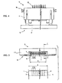
- Figs. 4, 5 and 6 show such an electric connector for flexible flat cables in detail. As shown, it has solder pieces 16 extending from housing 6 for fastening the connector to a printed circuit board (not shown). Also, cable fastening means 10 appears as actuator 17.
- the terminals 8 are arranged at same pitch as the pitch P at which the conductors 2 of the cable 1 are arranged.
- Each terminal 8 has a "U"-shaped cross section, and it has a solder tail portion 15 for soldering to a selected conductor on a printed circuit board.
- the longest lateral distance B' between the opposite side walls 13 and 14 of the connector housing is shorter than the width A of the flexible flat cable 1. This will cause the cable to form a curve.
- the longest lateral distance B' may be equal to or slightly greater than the width A of the flexible flat cable 1. Either condition will work with this invention.
- the actuator 17 is raised up in an unlocking position 18 (broken lines in Fig. 6).
- the contact portions 9 of the terminals 8 extend up from the floor wall 12 of the connector housing. Since the flexible flat cable 1 will initially form a curve as shown in Figure 3b or will be forced into a curve from a generally flat insertion as shown in Figure 2, the exposed conductors 2 face the floor wall of the connector housing.
- the actuator 17 is lowered to the locking condition 19 (solid lines in Fig. 6), thus completing the insertion position of the cable in the housing.
- the cable 1 is pushed against the floor wall 12 of the connector housing, changing its shape from the letter "C” to the letter “U” in cross section.
- the conductors 2 of the cable 1 are forced into contact with the terminals 8 of the connector 1.
- the actuator 17 and cable are moved toward the housing thereby locking the cable and actuator 17 in the housing.
- each side wall 13, 14 of the housing 6 has a tapered portion 20 extending at an angle from the ceiling wall 11 converging toward the floor wall 12 and a normal portion 21 extending at a right angle from the floor wall 12.
- the tapered and normal portions are joined together.
- the cable As the fastening means 10 or actuator 17 is lowered into the locking position, applying a force F to the cable 1, the cable is curved in the form of a circular arc. This permits the opposed longitudinal sides of the cable 1 to yieldingly bend so as to be automatically guided toward the lateral alignment position relative to the terminals 8 by the tapered portions 20 of the opposite side walls 13 and 14. The resilience of the bent cable creates the equilibrium condition. Finally, the cable 1 is pushed against the floor wall 12 of the connector housing 6 by the fastening means 10 or actuator 17 so that the cross section of the cable 1 is changed from "C"-shaped arc to a "U” shape, forcing the conductors 2 of the cable 1 into contact with the terminal contacts 9 of the connector housing 6, as seen from Fig. 3A.
- the trapezoidal cable insertion space with the reduced lateral dimension has the effect of facilitating insertion of a flexible flat cable equidistant from the side walls and of aligning the conductors of the cable in the connector housing relative to the terminals of the connector housing.
- Figs. 1, 2 and 3 show the connector housing as defining an enclosed space by its ceiling wall, floor wall and opposed side walls. It, however, should be noted that a connector housing having no ceiling wall 11 or floor wall 12 may be used.
- the connector housing may have no ceiling, and it may be composed of a floor wall and opposite diverging side walls, thus permitting a flexible flat cable to be put in the open enclosure from the top, pushing the cable against the floor wall, which has terminals fixed therein.
Landscapes
- Coupling Device And Connection With Printed Circuit (AREA)
- Multi-Conductor Connections (AREA)
Applications Claiming Priority (2)
| Application Number | Priority Date | Filing Date | Title |
|---|---|---|---|
| JP16614/94 | 1994-12-16 | ||
| JP1994016614U JP3014611U (ja) | 1994-12-16 | 1994-12-16 | 平型柔軟ケ−ブルの為のコネクタ |
Publications (2)
| Publication Number | Publication Date |
|---|---|
| EP0717462A2 true EP0717462A2 (de) | 1996-06-19 |
| EP0717462A3 EP0717462A3 (de) | 1998-03-04 |
Family
ID=11921213
Family Applications (1)
| Application Number | Title | Priority Date | Filing Date |
|---|---|---|---|
| EP95119770A Ceased EP0717462A3 (de) | 1994-12-16 | 1995-12-15 | Elektrischer Verbinder für flexibele Flachkabel |
Country Status (6)
| Country | Link |
|---|---|
| US (1) | US5632646A (de) |
| EP (1) | EP0717462A3 (de) |
| JP (1) | JP3014611U (de) |
| KR (1) | KR960027075A (de) |
| MY (1) | MY131713A (de) |
| SG (1) | SG49580A1 (de) |
Cited By (2)
| Publication number | Priority date | Publication date | Assignee | Title |
|---|---|---|---|---|
| EP0989632A1 (de) * | 1998-09-25 | 2000-03-29 | Molex Incorporated | Elektrischer Verbinder für flache Schaltungseinheiten |
| DE19957789A1 (de) * | 1999-12-01 | 2001-06-21 | Leoni Bordnetz Sys Gmbh & Co | Kontaktierungssystem für zwei Leiterplatten |
Families Citing this family (5)
| Publication number | Priority date | Publication date | Assignee | Title |
|---|---|---|---|---|
| DE19536131C2 (de) * | 1995-09-28 | 2002-05-02 | Saint Gobain Sekurit D Gmbh | Diversity-Antennenscheibe für Fahrzeuge mit Anschlußelementen |
| US6475027B1 (en) | 2000-07-18 | 2002-11-05 | Visteon Global Technologies, Inc. | Edge card connector adaptor for flexible circuitry |
| US7336139B2 (en) * | 2002-03-18 | 2008-02-26 | Applied Micro Circuits Corporation | Flexible interconnect cable with grounded coplanar waveguide |
| US8847696B2 (en) * | 2002-03-18 | 2014-09-30 | Qualcomm Incorporated | Flexible interconnect cable having signal trace pairs and ground layer pairs disposed on opposite sides of a flexible dielectric |
| US7121874B1 (en) | 2005-09-26 | 2006-10-17 | Myoungsoo Jeon | Flexible printed circuit (FPC) edge connector |
Family Cites Families (21)
| Publication number | Priority date | Publication date | Assignee | Title |
|---|---|---|---|---|
| IT1158641B (it) * | 1982-03-02 | 1987-02-18 | Zetronic Spa | Connettore rapido per circuito multipolare |
| FR2530384A1 (fr) * | 1982-07-15 | 1984-01-20 | Amp France | Procede et connecteur electrique pour terminer un conducteur d'un cable flexible plat |
| JPS61131382A (ja) * | 1984-11-29 | 1986-06-19 | アンプ インコ−ポレ−テツド | 電気コネクタ |
| NL8600224A (nl) * | 1986-01-30 | 1987-08-17 | Du Pont Nederland | Klemkontaktorgaan en uit meerdere van dergelijke klemkontaktorganen opgebouwde randkonnektor voor het verbinden van geleiders. |
| US4695108A (en) * | 1986-08-04 | 1987-09-22 | Hosiden Electronics Co., Ltd. | Connector for flexible printed circuit board |
| US4718859A (en) * | 1987-03-16 | 1988-01-12 | Molex Incorporated | Zero insertion force connector for flexible flat cable |
| JPH0162684U (de) * | 1987-10-16 | 1989-04-21 | ||
| JPH0438470Y2 (de) * | 1987-12-08 | 1992-09-09 | ||
| JPH088550Y2 (ja) * | 1988-01-14 | 1996-03-06 | アンプ インコーポレーテッド | フラットケーブル用コネクタ |
| JPH0286080A (ja) * | 1988-09-21 | 1990-03-27 | Nippon Burndy Kk | フラットケーブル用コネクタ |
| JPH0532945Y2 (de) * | 1989-03-15 | 1993-08-23 | ||
| JPH0635415Y2 (ja) * | 1989-10-06 | 1994-09-14 | コネクタ | |
| GB2244181B (en) * | 1990-04-13 | 1994-12-21 | Oki Electric Cable | Double lock male/female type connector |
| JP2764647B2 (ja) * | 1990-06-29 | 1998-06-11 | 蛇の目ミシン工業株式会社 | 刺繍縫い可能なミシン |
| JPH0724230B2 (ja) * | 1990-10-25 | 1995-03-15 | 京セラエルコ株式会社 | 無挿抜力コネクタ |
| US5240430A (en) * | 1991-10-31 | 1993-08-31 | Amp Incorporated | Electrical connector for cable to circit board application |
| US5308262A (en) * | 1991-12-10 | 1994-05-03 | Sumitomo Wiring Systems, Ltd. | Electric connector for flexible ribbon cable |
| US5194017A (en) * | 1992-02-24 | 1993-03-16 | Amp Incorporated | Connector for a flexible circuit |
| GB2272583B (en) * | 1992-11-12 | 1996-07-24 | Thomas & Betts Corp | Connector |
| JP2561501Y2 (ja) * | 1992-12-25 | 1998-01-28 | モレックス インコーポレーテッド | フレキシブルプリント回路基板接続用の電気コネクタ |
| JPH0722129A (ja) * | 1993-07-05 | 1995-01-24 | Kiyousera Elco Kk | Lcdコネクタ装置 |
-
1994
- 1994-12-16 JP JP1994016614U patent/JP3014611U/ja not_active Expired - Lifetime
-
1995
- 1995-11-14 US US08/557,878 patent/US5632646A/en not_active Expired - Fee Related
- 1995-12-14 MY MYPI95003876A patent/MY131713A/en unknown
- 1995-12-14 KR KR1019950049638A patent/KR960027075A/ko not_active Abandoned
- 1995-12-15 EP EP95119770A patent/EP0717462A3/de not_active Ceased
- 1995-12-15 SG SG1995002157A patent/SG49580A1/en unknown
Cited By (3)
| Publication number | Priority date | Publication date | Assignee | Title |
|---|---|---|---|---|
| EP0989632A1 (de) * | 1998-09-25 | 2000-03-29 | Molex Incorporated | Elektrischer Verbinder für flache Schaltungseinheiten |
| DE19957789A1 (de) * | 1999-12-01 | 2001-06-21 | Leoni Bordnetz Sys Gmbh & Co | Kontaktierungssystem für zwei Leiterplatten |
| US6564450B2 (en) | 1999-12-01 | 2003-05-20 | Leoni Bordnetz Sys Gmbh & Co | Contacting-making system for two printed circuit boards |
Also Published As
| Publication number | Publication date |
|---|---|
| MY131713A (en) | 2007-08-30 |
| SG49580A1 (en) | 1998-06-15 |
| US5632646A (en) | 1997-05-27 |
| JP3014611U (ja) | 1995-08-15 |
| KR960027075A (ko) | 1996-07-22 |
| EP0717462A3 (de) | 1998-03-04 |
Similar Documents
| Publication | Publication Date | Title |
|---|---|---|
| EP0667651B1 (de) | Elektrischer Verbinder | |
| US5240430A (en) | Electrical connector for cable to circit board application | |
| US4072387A (en) | Multiple conductor connector unit and cable assembly | |
| CN1126212C (zh) | 可以构形的接地面 | |
| US6162083A (en) | Electrical connector system for flat circuitry | |
| US4188086A (en) | Connector for terminating flexible parallel conductors | |
| EP0567007A2 (de) | Elektrischer Verbinder zur Oberflächenmontage | |
| WO2007127467A2 (en) | Insulation displacement terminal | |
| EP0540260B1 (de) | Elektrischer Verbinder zur Verbindung einer Leiterplatte mit einem Kabel | |
| EP0561288A1 (de) | Vorbelasteter Leiterplatten-Eckverbinder | |
| EP0239422A1 (de) | Elektrischer Steckverbinder für flexibles Flachkabel | |
| EP0544184A2 (de) | Vorrichtung zum Montieren eines Anschlusselements in einem elektrischen Steckverbinder | |
| US7047636B2 (en) | Method of connecting a connecting member and a flat circuit member | |
| US5934932A (en) | Electrical connector for flat cables | |
| US5921808A (en) | Ribbon cable plug-in connector | |
| EP0614250B1 (de) | Elektrischer Randverbinder für gedruckte Leiterplatten | |
| EP0610786B1 (de) | Schneidklemmanschlusssystem für elektrischen Ein-/Ausgangsverbinder | |
| GB2286492A (en) | Straddle electrical connector | |
| US5470246A (en) | Low profile edge connector | |
| EP0384591A1 (de) | Zugentlastungseinrichtung | |
| US5632646A (en) | Electric connector for flexible flat cables | |
| US20020127904A1 (en) | Relay connector | |
| JP3019288U (ja) | 平型柔軟ケーブル用電気コネクタ | |
| KR20140051068A (ko) | 커넥터 | |
| EP0641060B1 (de) | Elektrischer Kleinmotor mit Anschlusseinrichtung |
Legal Events
| Date | Code | Title | Description |
|---|---|---|---|
| PUAI | Public reference made under article 153(3) epc to a published international application that has entered the european phase |
Free format text: ORIGINAL CODE: 0009012 |
|
| AK | Designated contracting states |
Kind code of ref document: A2 Designated state(s): DE FR GB IT |
|
| PUAL | Search report despatched |
Free format text: ORIGINAL CODE: 0009013 |
|
| AK | Designated contracting states |
Kind code of ref document: A3 Designated state(s): DE FR GB IT |
|
| 17P | Request for examination filed |
Effective date: 19980821 |
|
| GRAG | Despatch of communication of intention to grant |
Free format text: ORIGINAL CODE: EPIDOS AGRA |
|
| 17Q | First examination report despatched |
Effective date: 19990331 |
|
| STAA | Information on the status of an ep patent application or granted ep patent |
Free format text: STATUS: THE APPLICATION HAS BEEN REFUSED |
|
| 18R | Application refused |
Effective date: 19990920 |