EP0717523A2 - Dynamisch kontrollierte Polarisationsmodulation in Wellenlängenmultiplex-Übertragungssystemen - Google Patents
Dynamisch kontrollierte Polarisationsmodulation in Wellenlängenmultiplex-Übertragungssystemen Download PDFInfo
- Publication number
- EP0717523A2 EP0717523A2 EP95308840A EP95308840A EP0717523A2 EP 0717523 A2 EP0717523 A2 EP 0717523A2 EP 95308840 A EP95308840 A EP 95308840A EP 95308840 A EP95308840 A EP 95308840A EP 0717523 A2 EP0717523 A2 EP 0717523A2
- Authority
- EP
- European Patent Office
- Prior art keywords
- optical
- polarization
- optical signal
- channels
- modulation
- Prior art date
- Legal status (The legal status is an assumption and is not a legal conclusion. Google has not performed a legal analysis and makes no representation as to the accuracy of the status listed.)
- Granted
Links
Images


Classifications
-
- H—ELECTRICITY
- H04—ELECTRIC COMMUNICATION TECHNIQUE
- H04B—TRANSMISSION
- H04B10/00—Transmission systems employing electromagnetic waves other than radio-waves, e.g. infrared, visible or ultraviolet light, or employing corpuscular radiation, e.g. quantum communication
- H04B10/50—Transmitters
- H04B10/516—Details of coding or modulation
- H04B10/532—Polarisation modulation
-
- H—ELECTRICITY
- H04—ELECTRIC COMMUNICATION TECHNIQUE
- H04B—TRANSMISSION
- H04B10/00—Transmission systems employing electromagnetic waves other than radio-waves, e.g. infrared, visible or ultraviolet light, or employing corpuscular radiation, e.g. quantum communication
- H04B10/25—Arrangements specific to fibre transmission
-
- H—ELECTRICITY
- H04—ELECTRIC COMMUNICATION TECHNIQUE
- H04J—MULTIPLEX COMMUNICATION
- H04J14/00—Optical multiplex systems
- H04J14/02—Wavelength-division multiplex systems
- H04J14/03—WDM arrangements
- H04J14/0305—WDM arrangements in end terminals
-
- H—ELECTRICITY
- H04—ELECTRIC COMMUNICATION TECHNIQUE
- H04B—TRANSMISSION
- H04B10/00—Transmission systems employing electromagnetic waves other than radio-waves, e.g. infrared, visible or ultraviolet light, or employing corpuscular radiation, e.g. quantum communication
- H04B10/25—Arrangements specific to fibre transmission
- H04B10/2581—Multimode transmission
Definitions
- This invention relates to the optical transmission of information. More particularly, this invention relates to polarization modulation in wavelength division multiplexed transmission systems.
- Wavelength-division multiplexing is expected to be increasingly utilized in undersea and transcontinental terrestrial optical transmission systems due, in part, to the large bandwidth capacity such multiplexing provides.
- wavelength division multiplexed transmission systems are susceptible to performance limitations due to polarization dependent effects, such as polarization-dependent hole burning in the erbium-doped fiber amplifiers that are typically used in such transmission systems, and cross-talk between the multiplexed channels.
- Polarization dependent hole burning is related to the population inversion dynamics of the erbium-doped fiber amplifiers.
- Cross-talk is primarily caused by the non-linear index of refraction of optical transmission fibers. Four-wave mixing is one significant deleterious effect that produces cross-talk.
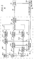
- FIG. 1 is a simplified block diagram of an illustrative arrangement of elements facilitating practice of the invention including an optical transmitter; an optical transmission path; a telemetry path; an optical receiver; and, a bit-error rate detector, in accordance with the invention.
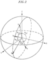
- FIG. 2 shows the states-of-polarization along a great circle trajectory on the Poincaré sphere for optical channels in the optical transmitter shown in FIG. 1, in accordance with the invention.
- FIGs. 3 and 4 schematically show an illustrative example of a dithering technique; in accordance with the invention.
- FIG. 5 is a simplified block diagram of a second illustrative arrangement of elements facilitating practice of the invention, in accordance with the invention.
- FIG. 6 is a simplified block diagram of a third illustrative arrangement of elements facilitating practice of the invention, in accordance with the invention.
- FIG. 7 is a simplified block diagram of a fourth illustrative arrangement of elements facilitating practice of the invention, in accordance with the invention.
- FIG. 8 is a simplified block diagram of a fifth illustrative arrangement of elements facilitating practice of the invention, in accordance with the invention.
- FIG. 1 is a simplified block diagram of an illustrative arrangement of elements facilitating practice of the invention. Shown are optical transmitter 100; optical transmission path 170; optical receiver 175; bit-rate error detector 178; and telemetry path 185.
- Optical transmitter 100 includes a plurality of optical sources 101 for producing a plurality of optical channels 102; a plurality of polarization controllers 106, 117, 121, and 129; Nx1 multiplexer 115; polarizing filter 112; polarization modulator 119; controller 130; and, adjustable birefringence element 122. It is noted at the onset that the term "channel" as used herein refers to any optical phenomena that is defined by a unique wavelength.
- the term channel may refer to a component of a wavelength division multiplexed optical signal having a plurality of components, where each component has a different wavelength.
- the term channel may refer to a monochromatic optical signal.
- the elements listed above forming optical transmitter 100 may be coupled using conventional means including, for example, optical fibers, which could include polarization maintaining optical fibers where appropriate.
- Optical transmitter 100 is coupled, as shown, to optical transmission path 170 and optical receiver 175 to form optical transmission system 190.
- Optical transmission system 190 may be, for example, a unidirectional system, as shown, or a bidirectional system utilizing additional optical transmitters and receivers (not shown) to facilitate communications in a reverse direction.
- Optical transmission paths and optical receivers are known.
- Optical receiver 175 is coupled to bit-error rate detector 178 which detects the rate of bit-errors in the received optical signal.
- Bit-error rate detectors are known. The functions of bit-error rate detector may optionally be incorporated directly into optical receiver 175.
- the bit-error rate is used to determine the optical signal-to-noise ratio, Q-factor, or other known figures-of-merit which provide an indication of overall performance of transmission system 190, or, performance of one or more selected optical channels.
- Q-factor representing average of the N optical channels is used as the performance indicator.
- Q-factor is described, for example, by Neal S. Bergano, F.W. Kerfoot, C.R.
- a signal representing the Q-factor is sent back to controller 130 in optical transmitter 100 via telemetry path 185.
- Telemetry path may be a separate path, or be part of optical transmission path 170 using, for example, overhead bits in data or signal frames such as a SONET frame traveling in the reverse direction. If a separate path is desired, then an order-wire channel or separate channel such as a telephone line may be utilized, for example.
- the Q-factor received by controller 130 in optical transmitter 100 is used, in accordance with the invention, to dynamically control adjustable birefringence element 122 and polarization controller 129. This dynamic control scheme is discussed below.
- the plurality of optical sources 101-1, 101-2, ... 101-N which may be, for example, wavelength-tunable semiconductor lasers, are utilized to generate a plurality of continuous-wave optical signals each having a different wavelength, ⁇ 1, ⁇ 2, ... ⁇ N , respectively, as shown, thus defining a plurality of N optical channels 102-1, 102-2 ... 102-N.
- Optical sources 101 may be adapted such that optical channels 102 have substantially identical optical power.
- One or more of the optical sources 101 may be adapted so that optical channels 102 carry information supplied by data sources (not shown) using conventional techniques.
- the optical channels 102 generated by optical sources 101 pass through polarization controllers 106, and are received by Nx1 multiplexer 115.
- Polarization controllers 106 are used to orient the state-of-polarization ("SOP") of each optical channel 102 so that they all have substantially the same SOP.
- SOP state-of-polarization
- Those skilled in the art will recognize that the common SOPs may be represented as a single point on the Poincaré sphere.
- the Poincaré sphere is well known, being described, for example, by William A. Shurcliff, Polarized Light: Production and Use , Harvard University Press, 1962.
- Nx1 multiplexer 115 could be, for example, an directional optical coupler that is known in the art.
- the output of Nx1 multiplexer is a wavelength division multiplexed optical signal 110 having N channels, where each channel is defined by a different wavelength ⁇ 1, ⁇ 2, ... ⁇ N .
- the channels may be sequentially numbered 1, 2, ... N, from lowest to highest wavelength.
- the channel wavelengths are uniformly spaced, for example, by 1 nm.
- non-uniform channel wavelength spacing can help reduce the effects of four-wave mixing.
- Wavelength division multiplexed optical signal 110 passes from Nx1 multiplexer 115 to polarization modulator 119 after passing through polarization controller 117 and polarizing filter 112.
- Polarization modulator 119 operates to continuously modulate the SOP of wavelength division multiplexed optical signal 110 so that no one polarization state is preferred during a time interval corresponding to one modulation cycle of polarization modulator 119.
- the polarization-modulated wavelength division multiplexed optical signal 120 output from polarization modulator 119 is essentially unpolarized, that is, the average value of its SOP over the modulation time interval is substantially equal to zero.
- such polarization modulation may significantly reduce the negative effects of polarization-dependent hole burning.
- polarization modulator 119 may modulate the SOP of wavelength division multiplexed optical signal 110 so that it traces a complete great circle on the Poincaré sphere.
- the SOP may reciprocate about the trajectory on the Poincaré sphere without tracing a complete great circle. Regardless of the particular trajectory chosen, it is important that the average value of the SOP over the modulation cycle be substantially equal to zero.
- Polarization modulators are known, and are often called polarization "scramblers.” In this illustrative example, it is intended that polarization modulator 119 be of a type that is disclosed in United States patent 5,327,511 (see, particularly figure 3 of that patent), the disclosure of which is incorporated by reference herein.
- polarization modulator 119 in this illustrative example is a polarization-dependent device, as are other known polarization modulators. Therefore, it may be desirable in some applications of the invention to utilize a strongly polarized input signal to polarization modulator 115.
- FIG. 1 shows polarizing filter 112 disposed at the input to polarization modulator 115. Polarizing filters are known. Polarization controller 117 is utilized to orient the SOP of the wavelength division multiplexed signal 110 to maximize the signal power transmitted to polarizing filter 112. It should be noted that polarizing filter 112 and polarization controller 117 are not required to facilitate the practice of the invention and, thus, should be considered optional. Alternatively, the functions of polarizing filter 112 may be incorporated directly into polarization modulator 119.
- the polarization modulated wavelength division multiplexed optical signal 120 output from polarization modulator 119 is passed to adjustable birefringence element 122 via polarization controller 121.
- Polarization controllers and adjustable birefringence elements are known.
- Polarization controller 121 may be, for example, the Lefevre-type polarization controller described by H.C. Lefevre in IEEE Electronics Letters , Vol. 16, p. 778, 1980.
- Adjustable birefringence device 122 is selected to have an adjustable propagation delay difference between it fast and slow axes thereby allowing a variable amount of birefringence to be selected. Adjustable birefringence elements are known.
- Adjustable birefringence element 122 could be, for example, a Babinet-Soleil compensator.
- Polarization controller 121 is utilized to place the great circle polarization modulation trajectory of the polarization-modulated wavelength multiplexed optical signal 120 into a plane which is perpendicular to a line on the Poincaré sphere which joins the fast and slows axes of adjustable birefringence element 122.
- Adjustable birefringence element 122 in accordance with the invention, advantageously allows the SOPs of the optical channels in the polarization modulated wavelength division multiplexed optical signal 120 to be varied relative to each other according to the amount of birefringence selected.
- FIG. 2 shows the manner in which SOPs for the optical channels in the polarization modulated wavelength division multiplexed optical signal 123 emerging from adjustable birefringence element are separated along a great circle trajectory on the Poincaré sphere.
- the separation of SOPs of the optical channels in the polarization modulated wavelength division multiplexed optical signal 120 is conveniently described by a separation angle ⁇ i,j , where the i and j subscripts identify optical channels having neighboring wavelengths.
- Adjustable birefringence element 122 dynamically adjusts the total birefringence and hence the separation angles ⁇ i , j , in response to control signal 132 from controller 130.
- separation angles ⁇ i , j may be non-uniform if non-uniform optical channel wavelength spacing is utilized. It may also be desirable to utilize a combination of uniform and non-uniform separation angles ⁇ i , j in some applications of the invention.
- the average separation angle ⁇ ⁇ i , j is dynamically adjusted to maximize the Q-factor as measured at optical receiver 175 for the plurality of N different optical channels. Accordingly, the actual separation angles ⁇ i , j at a given instant in time may vary from the initially selected values.
- the polarization modulated wavelength division multiplexed optical signal 123 emerging from adjustable birefringence element 122 is received by polarization controller 129 which operates to set the launch orientation of the SOP of polarization modulated wavelength division multiplexed optical signal 123 into optical transmission path 170.
- Polarization controller 129 dynamically adjusts the launch SOP in response to control signal 134 from controller 130 to farther maximize the Q-factor at optical receiver 175 as measured by bit-error rate detector 178.
- all the optical channels are simultaneously moving about a great circle polarization trajectory, as discussed above, such that the substantially zero average value of the SOP of the wavelength division multiplexed optical signal 123 is maintained.
- the effects of polarization-dependent hole burning and four-wave mixing are simultaneously and significantly reduced in optical transmission systems.
- this performance improvement is realized even as changing environmental conditions and other factors affect polarization-dependent hole burning and four-wave mixing in optical transmission system 190.
- controller 130 dynamically controls two parameters --the average separation angle ⁇ ⁇ i , j and launch SOP -- in order to maximize the Q-factor at optical receiver 175 as measured by bit-error rate detector 178. It is emphasized, however, that dynamic control of just one or the other parameter is intended to fall within the spirit and scope of the present invention.
- the control technique used by controller 130 may be, for example, a simple cause and effect scheme which sequentially adjusts separation angles ⁇ i , j and launch SOP in small steps until a measured Q-factor maxima is obtained.
- a dithering technique may be employed where these parameters are varied in positive and negative amounts around a starting point, and the resulting Q-factor is measured by bit-error rate detector 178.
- FIGs. 3 and 4 schematically show an example of a dithering technique using the Poincaré sphere.
- the starting SOP is represented by vector 302.
- the dither trajectory 303 is drawn around the starting SOP as a circle on the Poincaré sphere, with the endpoint of vector 302 as its center.
- Polarization controller 129 is adjusted such that the SOP precesses about the circular dither trajectory.
- the Q-factor of the received signal is measured.
- the initial condition vector 302 is then replaced with vector 404, as shown in FIG. 4, which represents the SOP on the dither trajectory 303 resulting in the best Q-factor.
- a new circular dither trajectory 405 is then drawn using the endpoint of vector 404 as its center, and the process above is repeated.
- FIG. 5 shows a simplified block diagram of a second illustrative arrangement of elements, in accordance with the invention. Shown are optical transmitter 500; optical transmission path 570; optical receiver 575; bit-error rate detector 578; and telemetry path 585.
- Optical transmission path 570, optical receiver 575, bit-error rate detector 578, and telemetry path 585 are similar in form and operation to those corresponding elements shown in FIG. 1.
- Optical transmitter 500 includes a plurality of optical sources 501 for producing a plurality of continuous-wave optical channels 502; a plurality of polarization modulators 510; a plurality of polarization controllers 514 and 540; Nx1 multiplexer 515; and, polarization modulation controller 520.
- Optical transmitter 500 is coupled, as shown, to optical transmission path 570 and optical receiver 575 to form optical transmission system 590.
- polarization modulation controller 520 dynamically controls the polarization modulation of optical channels 502 in response to a signal representing the Q-factor, as with the previous illustrative example, from bit-error rate detector 578 on telemetry path 585.
- Polarization modulation controller may also optionally dynamically control polarization modulator 540, as shown.
- the plurality of optical sources 501-1, 502-2, ... 501-N generate a plurality of optical signals each having a different wavelength, ⁇ 1, ⁇ 2, ... ⁇ N , respectively, as shown, thus defining a plurality of N optical channels 502-1, 502-2, ... 502-N.
- Optical sources 501 may be adapted such that optical channels 502 have substantially identical optical power.
- each optical channel 502 passes through individual polarization modulators 510 and individual polarization controllers 514.
- Polarization modulators 510-1, 510-2, ... 510-N modulate the SOPs of optical channels 502-1, 502-2, ... 502-N, respectively, in response to polarization modulation control signals ⁇ 1, ⁇ 2 ...
- ⁇ and A may be variable.
- the amplitude A may be adjusted such that the average values of SOPs of the optical channels are substantially equal to zero..
- polarization modulators 510 operate to continuously modulate the SOP optical channels 502 so that no one polarization state is preferred during a time interval corresponding to one modulation cycle of polarization modulators 510.
- each of the optical channels 502 output from polarization modulators 510 is essentially unpolarized, that is, the average value of the SOPs over the modulation time interval is substantially equal to zero.
- each polarization modulator 510 may modulate the SOP of an optical channel 502 so that it traces a complete great circle on the Poincaré sphere.
- the SOP may reciprocate about the trajectory on the Poincaré sphere without tracing a complete great circle. Again, regardless of the particular trajectory chosen, it is important that the average value of the SOP of optical channels 502 over the modulation cycle be substantially equal to zero.
- the polarization modulated optical channels 511 emerging from polarization modulators 510 are received by Nx1 multiplexer 515 where they are combined into a single wavelength division multiplexed optical signal 523.
- the polarization modulation described above results in the average value of the SOP of each optical channel 502 being substantially equal to zero over each modulation cycle. Therefore, the average value of the SOP of wavelength division multiplexed optical signal 523 is also substantially equal to zero over each modulation cycle.
- ⁇ i the relative phase, ⁇ i , of the modulation frequency drive signals ⁇ i in equation (1) under the control of polarization modulation controller 520, and by adjusting polarization controllers 514, all of the SOPs of the polarization-modulated optical channels 511 are separated along some particular great circle trajectory on the Poincaré sphere in a similar arrangement as shown in FIG. 2.
- the SOPs may be independent, that is they do not share the same great circle on the Poincaré sphere.
- polarization controllers 514 are utilized in this illustrative example of the invention to orient the SOPs of optical channels 511 emerging from polarization modulators 510 into the same great circle trajectory.
- separation angle ⁇ i , j is conveniently described by separation angle ⁇ i , j on the Poincaré sphere as shown in FIG. 2.
- polarization modulators 510 dynamically adjust the relative phase of the modulation frequency drive signals, ⁇ i ,, and hence the separation angles ⁇ i , j , in response to the modulation frequency drive signals ⁇ i from polarization modulation controller 520.
- the initial separation angles ⁇ i , j may be, for example, approximately 180°, such that SOPs of odd-numbered channels are substantially orthogonal to even-numbered channels.
- the separation angles ⁇ i , j are dynamically adjusted to maximize the Q-factor as measured at optical receiver 575.
- Polarization controller 540 is utilized at the output of Nx1 multiplexer 515 to set the launch orientation of the SOP of the wavelength division multiplexed output signal into optical transmission path 585. It is noted that polarization controller 540 is optional as it merely provides additional flexibility in polarization control.
- Polarization controller 540 may set the launch SOP orientation in response to control signal 534 from polarization modulation controller 520.
- Polarization modulation controller 520 may control the separation angles ⁇ i , j and launch SOP using the sequential cause and effect scheme or the dithering technique described above when referring to FIGs. 3 and 4.
- FIG. 6 is a simplified block diagram of a third illustrative arrangement of elements, in accordance with the invention. Shown are optical transmitter 600; optical transmission path 670; optical receiver 675; bit-error rate detector 678; and telemetry path 685. Optical transmission path 670, optical receiver 675, bit-error rate detector 678, and telemetry path 685 are similar in form and operation as those corresponding elements shown in FIG. 1. Optical transmitter 600 is coupled, as shown, to an optical transmission path 670 and optical receiver 675 to form an optical transmission system 690.
- Optical transmitter 600 includes a plurality of data sources 680, a plurality of data modulators 685; a plurality of optical sources 601 for producing a plurality of optical channels 602; a plurality of polarization controllers 606, 617, 621, and 629; Nx1 multiplexer 615; polarizing filter 612; polarization modulator 619; clock 676; phase shifter 620; controller 630; and, adjustable birefringence element 622. It is noted that the elements forming optical transmitter 600 are similar in form, arrangement, and operation to those shown in FIG. 1, with the additions of data sources 680, data modulators 685, phase shifter 620 and clock 676.
- Data modulators 685 receive data to be imparted to the optical channels 602 from data sources 680 and modulate the optical channels 602 at a frequency determined by clock 676.
- clock 676 also drives polarization modulator 619 via a variable delay line, for example, phase shifter 620 as shown, so that the SOP of the wavelength division optical signal 616 emerging from Nx1 multiplexer 615 is polarization modulated at a rate equal to the rate at which data is imparted to the optical channels 602.
- clock 676 causes the rate of polarization modulation to be frequency and phase locked to the rate of data modulation. While phase shifter 620 is shown in FIG. 6, it contemplated that any variable-delay line may be used.
- phase shifter 620 is utilized to adjust the relative timing between the polarization and data modulation.
- this relative timing adjustment may also be implemented using a plurality of variable delay lines, where one delay line is disposed between each data modulator 685 and Nx1 multiplexer 615 either upstream or downstream of polarization controllers 606.
- a plurality of variable delay lines may also be utilized between clock 676 and data modulators 685, either upstream or downstream of data sources 680.
- the relative timing adjustment between polarization and phase modulation may be effectuated, in accordance with the invention, by introducing delay on the plurality of optical channels, or by introducing delay on the wavelength division multiplexed optical signal, or by utilizing combinations thereof.
- the scope of the invention is intended to include the performance of synchronous data and polarization modulation on all optical channels, or selected optical channels.
- Such synchronous polarization and data modulation advantageously provides for a wavelength division multiplexed transmitter having a near optimal balance between low speed and high speed polarization modulation which minimizes the deleterious effects of AM modulation caused by low speed modulation and increased bandwidth caused by high speed modulation.
- FIG. 7 is a simplified block diagram of a fourth illustrative arrangement of elements, in accordance with the invention. Shown are optical transmitter 700; optical transmission path 770; optical receiver 775; bit-error rate detector 778; and telemetry path 785.
- Optical transmitter 700 includes a plurality of data sources 780, a plurality of data modulators 785; a plurality of optical sources 701 for producing a plurality of optical channels 702; a plurality of polarization controllers 706, 717, 721, and 729; Nx1 multiplexer 715; polarizing filter 712; polarization modulator 719; clock 776; phase shifters 720 and 786; optical phase modulator 784; controller 730; and, adjustable birefringence element 722, which are coupled as shown.
- Optical transmitter is coupled to optical transmission path 770 and optical receiver 775 to form optical transmission system 790.
- Bit-error rate detector 778 is coupled to optical receiver 775 and transmits a signal representative of a figure-of-merit, such as Q-factor, to controller 730 in optical transmitter 700 via telemetry path 785.
- a signal representative of a figure-of-merit such as Q-factor
- clock 776 simultaneously drives both polarization modulator 719 and phase modulator 784 via phase shifters 720 and 786, respectively.
- Optical phase modulator 784 modulates the optical phase of wavelength division multiplexed optical signal 716 without modulating the polarization of the signal.
- optical phase modulator 784 can be adapted to impart a fixed amount of phase shift to the wavelength division multiplexed optical signal 716 emerging from Nx1 multiplexer 715.
- phase shifter 786 may be deleted.
- phase shifters 720 and 785 are described in my co-pending European patent application Serial No. 95306638.8.
- phase modulator 784 may be incorporated directly into polarization modulator 719, which may be desirable in some applications of the invention, in which case phase modulator 784 may be deleted.
- FIG. 8 is a simplified block diagram of an fifth illustrative arrangement of elements, in accordance with the invention. Shown are optical transmitter 800; optical transmission path 870; optical receiver 875; bit-error rate detector 878; and telemetry path 885.
- Optical transmitter 800 includes a plurality of data sources 880, a plurality of data modulators 885, a plurality of optical sources 801 for producing a plurality of optical channels 802; a plurality of polarization modulators 810; a plurality of polarization controllers 806 and 840; Nx1 multiplexer 815; polarization modulation controller 820; and, clock 876 which are coupled as shown.
- Optical transmitter 800 is coupled to optical transmission path 870 optical receiver 875 to form optical transmission system 890.
- Bit-error rate detector 878 is coupled to optical receiver 875 and transmits a signal representative of a figure-of-merit (Q-factor in this illustrative example) to polarization modulation controller 820 in optical transmitter 800 via telemetry path 885.
- the elements shown in FIG. 8 are similar in form, arrangement, and operation to those shown in FIG. 5 with the addition of data sources 880, data modulators 885, and clock 876 which are utilized to synchronize data and polarization modulation as discussed above when referring to FIG. 6.
- Data modulators 885 receive data to be imparted to the optical signals 802 from data sources 880 and modulate the optical channels 802 at a frequency determined by clock 876.
- clock 876 also drives polarization modulators 810 so that the SOP of optical channels 802 are polarization modulated at a rate equal to the rate at which data is imparted to the optical channels 802. This synchronous data and polarization modulation is performed in a similar manner as that described when referring to FIG. 6.
- variable delay line such as a phase shifter, utilized in the previous illustrative example of synchronous data and polarization modulation, is not required in this illustrative example of the invention because phase delay is readily performed by polarization modulators 810 under the control of polarization modulation controller 820.
- the excess phase modulation technique described when referring to FIG. 7 may also be performed by polarization modulators 810 under the control of polarization modulation controller 820, because the relative phase between optical channels 802 may be readily varied as described above when referring to FIG. 6.
- variably delay lines may also be utilized to introduce a phase adjustment between the data and phase modulation, as in FIG. 6.
- a variable delay line such as a phase shifter, is disposed between each data modulator 885 and polarization modulator 810, and is coupled to clock 876.
- the wavelengths output by the optical sources, or the amplitude of the output signals may be controlled.
Landscapes
- Engineering & Computer Science (AREA)
- Computer Networks & Wireless Communication (AREA)
- Signal Processing (AREA)
- Physics & Mathematics (AREA)
- Electromagnetism (AREA)
- Optical Communication System (AREA)
Applications Claiming Priority (2)
| Application Number | Priority Date | Filing Date | Title |
|---|---|---|---|
| US35578894A | 1994-12-14 | 1994-12-14 | |
| US355788 | 1994-12-14 |
Publications (3)
| Publication Number | Publication Date |
|---|---|
| EP0717523A2 true EP0717523A2 (de) | 1996-06-19 |
| EP0717523A3 EP0717523A3 (de) | 1997-05-02 |
| EP0717523B1 EP0717523B1 (de) | 2004-11-17 |
Family
ID=23398852
Family Applications (1)
| Application Number | Title | Priority Date | Filing Date |
|---|---|---|---|
| EP95308840A Expired - Lifetime EP0717523B1 (de) | 1994-12-14 | 1995-12-06 | Dynamisch kontrollierte Polarisationsmodulation in Wellenlängenmultiplex-Übertragungssystemen |
Country Status (8)
| Country | Link |
|---|---|
| EP (1) | EP0717523B1 (de) |
| JP (1) | JP3744992B2 (de) |
| KR (1) | KR960027597A (de) |
| AU (1) | AU4039095A (de) |
| CA (1) | CA2164355C (de) |
| DE (1) | DE69533772T2 (de) |
| MX (1) | MX9505237A (de) |
| TW (1) | TW293211B (de) |
Cited By (5)
| Publication number | Priority date | Publication date | Assignee | Title |
|---|---|---|---|---|
| GB2307368A (en) * | 1995-11-17 | 1997-05-21 | Fujitsu Ltd | Scrambling the polarisation of wavelength division multiplexed signals |
| GB2350737A (en) * | 1995-11-17 | 2000-12-06 | Fujitsu Ltd | Polarization scrambling wavelength division multiplexed signals |
| US6459518B1 (en) | 1998-06-12 | 2002-10-01 | Kdd Corporation | Optical transmitting apparatus |
| WO2002060096A3 (en) * | 2001-01-25 | 2003-10-23 | Axe Inc | Automatic polarization controller for polarization multiplexed optical signals |
| WO2012049407A1 (fr) * | 2010-10-15 | 2012-04-19 | France Telecom | Compensation de dispersion modale de polarisation par brouillage deterministe de polarisation |
Family Cites Families (3)
| Publication number | Priority date | Publication date | Assignee | Title |
|---|---|---|---|---|
| DE3716247C2 (de) * | 1987-05-15 | 1994-04-28 | Sel Alcatel Ag | Optisches Nachrichtenübertragungssystem mit Wellenlängen- und Polarisations-Multiplex |
| JP2540935B2 (ja) * | 1989-03-16 | 1996-10-09 | 日本電気株式会社 | 一括偏波制御方法 |
| US5327511A (en) * | 1993-06-18 | 1994-07-05 | At&T Bell Laboratories | Apparatus and method employing fast polarization modulation to reduce effects of polarization hole burning and polarization dependent loss |
-
1995
- 1995-12-04 CA CA002164355A patent/CA2164355C/en not_active Expired - Fee Related
- 1995-12-06 EP EP95308840A patent/EP0717523B1/de not_active Expired - Lifetime
- 1995-12-06 DE DE69533772T patent/DE69533772T2/de not_active Expired - Fee Related
- 1995-12-06 TW TW084112999A patent/TW293211B/zh active
- 1995-12-12 AU AU40390/95A patent/AU4039095A/en not_active Abandoned
- 1995-12-13 MX MX9505237A patent/MX9505237A/es unknown
- 1995-12-13 KR KR1019950052344A patent/KR960027597A/ko not_active Withdrawn
- 1995-12-14 JP JP32528895A patent/JP3744992B2/ja not_active Expired - Fee Related
Cited By (10)
| Publication number | Priority date | Publication date | Assignee | Title |
|---|---|---|---|---|
| GB2307368A (en) * | 1995-11-17 | 1997-05-21 | Fujitsu Ltd | Scrambling the polarisation of wavelength division multiplexed signals |
| US5841557A (en) * | 1995-11-17 | 1998-11-24 | Fujitsu Limited | Method and apparatus for scrambling the polarization of signal lights forming a wavelength division multiplexed signal light |
| GB2350737A (en) * | 1995-11-17 | 2000-12-06 | Fujitsu Ltd | Polarization scrambling wavelength division multiplexed signals |
| GB2307368B (en) * | 1995-11-17 | 2000-12-27 | Fujitsu Ltd | Method and apparatus for scrambling the polarization of signal lights forming a wavelength division multiplied signal light |
| GB2350737B (en) * | 1995-11-17 | 2001-01-24 | Fujitsu Ltd | Method and apparatus for scrambling the polarization of light signals |
| US6459518B1 (en) | 1998-06-12 | 2002-10-01 | Kdd Corporation | Optical transmitting apparatus |
| WO2002060096A3 (en) * | 2001-01-25 | 2003-10-23 | Axe Inc | Automatic polarization controller for polarization multiplexed optical signals |
| WO2012049407A1 (fr) * | 2010-10-15 | 2012-04-19 | France Telecom | Compensation de dispersion modale de polarisation par brouillage deterministe de polarisation |
| FR2966309A1 (fr) * | 2010-10-15 | 2012-04-20 | France Telecom | Compensation de dispersion modale de polarisation par brouillage deterministe de polarisation |
| US9020357B2 (en) | 2010-10-15 | 2015-04-28 | Orange | Compensation of modal dispersion of polarization by deterministic jamming of polarization |
Also Published As
| Publication number | Publication date |
|---|---|
| CA2164355A1 (en) | 1996-06-15 |
| JP3744992B2 (ja) | 2006-02-15 |
| EP0717523B1 (de) | 2004-11-17 |
| DE69533772D1 (de) | 2004-12-23 |
| TW293211B (de) | 1996-12-11 |
| EP0717523A3 (de) | 1997-05-02 |
| CA2164355C (en) | 2000-12-19 |
| JPH08237224A (ja) | 1996-09-13 |
| MX9505237A (es) | 1997-01-31 |
| DE69533772T2 (de) | 2005-03-31 |
| KR960027597A (ko) | 1996-07-22 |
| AU4039095A (en) | 1996-06-20 |
Similar Documents
| Publication | Publication Date | Title |
|---|---|---|
| CA2323744C (en) | Method and apparatus for improving spectral efficiency in wavelength division multiplexed transmission systems | |
| AU639177B2 (en) | Polarization multiplexing with solitons | |
| US6459515B1 (en) | Method and apparatus for transmitting a WDM optical signal having states of polarization that are pairwise orthogonal | |
| US5805321A (en) | Control unit for optical modulators producing multiplexed optical output signal | |
| US7574143B2 (en) | All-optical signal processing method and device | |
| US5625479A (en) | Soliton optical communication system and optical transmitter and optical receiver therefor | |
| EP0660549A1 (de) | Zweiwellenlängendatensender zur Reduzierung von Fading in einem optischen Übertragungssystem | |
| US7512338B2 (en) | Method and apparatus for pulse generation and adaptive pulse generation for optical communications | |
| US20020003641A1 (en) | Polarization division multiplexer | |
| EP2343846A2 (de) | Polisationsmultiplexsender und Übertragungssystem | |
| EP0717524B1 (de) | Polarisationsmodulation in Wellenlängen-Multiplex Übertragungssystemen | |
| US20040016874A1 (en) | Automatic polarization controller for polarization multiplexed optical signals | |
| US6577413B1 (en) | Method and apparatus for polarization multiplexing and demultiplexing optical tributary signals | |
| EP0717523B1 (de) | Dynamisch kontrollierte Polarisationsmodulation in Wellenlängenmultiplex-Übertragungssystemen | |
| US6486990B1 (en) | Method and apparatus for communicating a clock signal in a soliton optical transmission system | |
| US6411413B1 (en) | Method and apparatus for performing dispersion compensation without a change in polarization and a transmitter incorporating same | |
| JP2019200379A (ja) | 波長変換装置、伝送装置、及び伝送システム | |
| US20030108265A1 (en) | Polarization multiplexed optical clock | |
| US20030108263A1 (en) | Polarization multiplexed optical data modulator | |
| WO2000072492A1 (en) | Polarization-division multiplexing based on power encoding of different polarization channels |
Legal Events
| Date | Code | Title | Description |
|---|---|---|---|
| PUAI | Public reference made under article 153(3) epc to a published international application that has entered the european phase |
Free format text: ORIGINAL CODE: 0009012 |
|
| AK | Designated contracting states |
Kind code of ref document: A2 Designated state(s): DE FR GB IT NL SE |
|
| PUAL | Search report despatched |
Free format text: ORIGINAL CODE: 0009013 |
|
| AK | Designated contracting states |
Kind code of ref document: A3 Designated state(s): DE FR GB IT NL SE |
|
| 17P | Request for examination filed |
Effective date: 19971016 |
|
| RAP1 | Party data changed (applicant data changed or rights of an application transferred) |
Owner name: TYCO SUBMARINE SYSTEMS LTD. |
|
| 17Q | First examination report despatched |
Effective date: 20020306 |
|
| RAP1 | Party data changed (applicant data changed or rights of an application transferred) |
Owner name: TYCO TELECOMMUNICATIONS (US) INC. |
|
| GRAP | Despatch of communication of intention to grant a patent |
Free format text: ORIGINAL CODE: EPIDOSNIGR1 |
|
| GRAP | Despatch of communication of intention to grant a patent |
Free format text: ORIGINAL CODE: EPIDOSNIGR1 |
|
| GRAS | Grant fee paid |
Free format text: ORIGINAL CODE: EPIDOSNIGR3 |
|
| GRAA | (expected) grant |
Free format text: ORIGINAL CODE: 0009210 |
|
| RIN1 | Information on inventor provided before grant (corrected) |
Inventor name: DAVIDSON, CARL R. Inventor name: BERGANO, NEAL S. |
|
| RAP1 | Party data changed (applicant data changed or rights of an application transferred) |
Owner name: TYCO TELECOMMUNICATIONS (US) INC. |
|
| AK | Designated contracting states |
Kind code of ref document: B1 Designated state(s): DE FR GB IT NL SE |
|
| PG25 | Lapsed in a contracting state [announced via postgrant information from national office to epo] |
Ref country code: SE Free format text: LAPSE BECAUSE OF FAILURE TO SUBMIT A TRANSLATION OF THE DESCRIPTION OR TO PAY THE FEE WITHIN THE PRESCRIBED TIME-LIMIT Effective date: 20041117 Ref country code: NL Free format text: LAPSE BECAUSE OF FAILURE TO SUBMIT A TRANSLATION OF THE DESCRIPTION OR TO PAY THE FEE WITHIN THE PRESCRIBED TIME-LIMIT Effective date: 20041117 |
|
| REG | Reference to a national code |
Ref country code: GB Ref legal event code: FG4D |
|
| REF | Corresponds to: |
Ref document number: 69533772 Country of ref document: DE Date of ref document: 20041223 Kind code of ref document: P |
|
| NLV1 | Nl: lapsed or annulled due to failure to fulfill the requirements of art. 29p and 29m of the patents act | ||
| ET | Fr: translation filed | ||
| PLBE | No opposition filed within time limit |
Free format text: ORIGINAL CODE: 0009261 |
|
| STAA | Information on the status of an ep patent application or granted ep patent |
Free format text: STATUS: NO OPPOSITION FILED WITHIN TIME LIMIT |
|
| 26N | No opposition filed |
Effective date: 20050818 |
|
| PGFP | Annual fee paid to national office [announced via postgrant information from national office to epo] |
Ref country code: GB Payment date: 20071227 Year of fee payment: 13 |
|
| PGFP | Annual fee paid to national office [announced via postgrant information from national office to epo] |
Ref country code: DE Payment date: 20080131 Year of fee payment: 13 Ref country code: IT Payment date: 20071228 Year of fee payment: 13 |
|
| PGFP | Annual fee paid to national office [announced via postgrant information from national office to epo] |
Ref country code: FR Payment date: 20071217 Year of fee payment: 13 |
|
| GBPC | Gb: european patent ceased through non-payment of renewal fee |
Effective date: 20081206 |
|
| REG | Reference to a national code |
Ref country code: FR Ref legal event code: ST Effective date: 20090831 |
|
| PG25 | Lapsed in a contracting state [announced via postgrant information from national office to epo] |
Ref country code: DE Free format text: LAPSE BECAUSE OF NON-PAYMENT OF DUE FEES Effective date: 20090701 |
|
| PG25 | Lapsed in a contracting state [announced via postgrant information from national office to epo] |
Ref country code: GB Free format text: LAPSE BECAUSE OF NON-PAYMENT OF DUE FEES Effective date: 20081206 |
|
| PG25 | Lapsed in a contracting state [announced via postgrant information from national office to epo] |
Ref country code: FR Free format text: LAPSE BECAUSE OF NON-PAYMENT OF DUE FEES Effective date: 20081231 |
|
| PG25 | Lapsed in a contracting state [announced via postgrant information from national office to epo] |
Ref country code: IT Free format text: LAPSE BECAUSE OF NON-PAYMENT OF DUE FEES Effective date: 20081206 |