EP0717581A1 - Induktionsheizsystem - Google Patents
Induktionsheizsystem Download PDFInfo
- Publication number
- EP0717581A1 EP0717581A1 EP95500161A EP95500161A EP0717581A1 EP 0717581 A1 EP0717581 A1 EP 0717581A1 EP 95500161 A EP95500161 A EP 95500161A EP 95500161 A EP95500161 A EP 95500161A EP 0717581 A1 EP0717581 A1 EP 0717581A1
- Authority
- EP
- European Patent Office
- Prior art keywords
- power
- circuit
- switch
- coil
- induction heating
- Prior art date
- Legal status (The legal status is an assumption and is not a legal conclusion. Google has not performed a legal analysis and makes no representation as to the accuracy of the status listed.)
- Withdrawn
Links
- 238000010438 heat treatment Methods 0.000 title claims abstract description 15
- 230000006698 induction Effects 0.000 title claims abstract description 12
- 238000001514 detection method Methods 0.000 claims abstract description 6
- 230000004913 activation Effects 0.000 claims description 5
- 230000009849 deactivation Effects 0.000 claims description 2
- 239000003990 capacitor Substances 0.000 abstract 1
- 230000003213 activating effect Effects 0.000 description 5
- 230000000694 effects Effects 0.000 description 2
- 230000005294 ferromagnetic effect Effects 0.000 description 2
- 238000009423 ventilation Methods 0.000 description 2
- 230000002159 abnormal effect Effects 0.000 description 1
- 230000033228 biological regulation Effects 0.000 description 1
- 238000010411 cooking Methods 0.000 description 1
- 230000003111 delayed effect Effects 0.000 description 1
- 238000010586 diagram Methods 0.000 description 1
- 230000002401 inhibitory effect Effects 0.000 description 1
- 230000005291 magnetic effect Effects 0.000 description 1
- 238000012423 maintenance Methods 0.000 description 1
- 230000007257 malfunction Effects 0.000 description 1
- 238000000034 method Methods 0.000 description 1
- 238000013021 overheating Methods 0.000 description 1
- 230000001105 regulatory effect Effects 0.000 description 1
- 230000003068 static effect Effects 0.000 description 1
- 239000013589 supplement Substances 0.000 description 1
- 230000001360 synchronised effect Effects 0.000 description 1
Images
Classifications
-
- H—ELECTRICITY
- H05—ELECTRIC TECHNIQUES NOT OTHERWISE PROVIDED FOR
- H05B—ELECTRIC HEATING; ELECTRIC LIGHT SOURCES NOT OTHERWISE PROVIDED FOR; CIRCUIT ARRANGEMENTS FOR ELECTRIC LIGHT SOURCES, IN GENERAL
- H05B6/00—Heating by electric, magnetic or electromagnetic fields
- H05B6/02—Induction heating
- H05B6/06—Control, e.g. of temperature, of power
- H05B6/062—Control, e.g. of temperature, of power for cooking plates or the like
Definitions
- the following invention consists of an induction heating system, the purpose of which is to supply the pot to be heated with high power with high efficiency and a minimized generation of electromagnetic interference, due to the soft switching of power devices.
- the said system has two different power control paths, one for low powers and one for high.
- the power reference level is varied
- a fixed power rate is applied at varied intervals.
- the known induction heating systems comprise a flat coil through which a high frequency current circulates causing the heating of the ferromagnetic pot, due to the phenomena of magnetic hysteresis and Joule effect by Foucault currents.
- This type of device is connected to the network via the corresponding filter and rectifier bridge.
- the former apart from the above mentioned elements, uses a power circuit basically determined by a transistor and its corresponding compensating network.
- This structure is designed for low powers and therefore has the inconvenience that the power device cannot withstand high powers of over 1400 watts
- this Patent as well as some others, performs a slow pot detection, which is another inconvenience.
- the power device is similarly based on the use of a transistor, which presents the same inconvenience as above.
- pot detection is performed by sensing input power, which also means the system is slow.
- the invention is characterised by the fact that the power stage comprises two transistors, arranged in series, such that they can withstand rated powers of 2000 watts and peaks of 4000 watts.
- the power control circuit counts on means for varying the power level which keeps it at a fixed level when the selected power is low and produces a power level variation at high powers.
- the power variation means are determined by a digital/analog converter unit, which generates a reference signal in proportion to the power chosen when in high powers, and a fixed reference when in low.
- the digital/analog converter is connected to a power control circuit which compares the current circulating through the coil, or through the mains, with the reference signal, the activating signal of the power elements being thus generated by it.
- the power variation means count on a circuit that generates the deactivating signal of the power elements, which is connected, along with that of the activating signal, to a circuit processing both signals and applying them to the driver of the power elements, the proper power being thus obtained.
- the deactivating circuit compares the current circulating through the coil with itself but out-of-phase to a certain degree, such that it controls the off time for the power elements.
- the energy variation means consist of a decoder that generates a signal proportional to the power selected when in low powers, and a fixed reference when in high.
- the decoder is connected to a switch-on/switch-off circuit which is in turn connected to the activating-deactivating circuit for the power elements as above mentioned, such that in low powers a constant power is supplied at different intervals, as established by the decoder, the energy being so varied.
- the fixed reference in high powers shows that power must be supplied continuously and not switched on and off at intervals.
- switch-on/switch-off circuit and the circuit generating the activating signal are connected to a zero-point detector, in order to ensure smoother performance that prevents interference.
- the invention detects the pot on the coil using a comparison unit to detect the current flowing through one of the balance networks for the power elements and compares it with a fixed reference, such that, when no pot has been placed on the coil, or the pot is not suitable, a higher current will circulate through the balance networks. This is detected by the comparison unit, inhibiting the activation circuit and causing the system to disconnect in a minimal time.
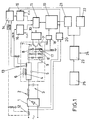
- Figure 1 shows a functional block diagram of the invention's induction heating system.
- the power circuit is determined by two transistors 7 and 7', arranged in series.
- the execution in the example has used transistors IGBT, with their corresponding antiparallel diodes 8 and 8'.
- the corresponding static and dynamic compensation network 9 is included.
- This arrangement of two transistors in series allows the withstanding of rated powers of 2000 W and peak powers of 4000 W. This means that the coil has to withstand very high voltages of around 900 volts.
- the power is selected by the user via the user interface 25 which can be determined by electromechanical controls, capacitive sensors, etc.
- This module is connected to a circuit that generates the power level 23, to which a temperature feedback 24 is applied to correct the power selection made by the user, as a function of the existing temperature in the pot-coil and transistors 7 and 7', with NTC being included in each of these elements.
- the feedback signal 24 for this adjustment is the measured temperature and its derivative or gradient.
- the system supplies a signal proportional to the said value to the decodifier 21 and the digital/analog converter 22.
- the digital/analog converter 22 is connected to the power control circuit 14, which in turn is connected via the current sensor 13 to the flat coil 4 or via the current sensor 12 to the network.
- the latter connection being optional, has been represented by a dash line.
- the digital/analog converter 22 generates a reference signal for the power control circuit 14, which compares it with the network current or coil 4 current, in order to adjust power so that, if the signal in coil IBOB or the signal in mains IRED exceed the reference signal provided by the digital/analog converter 22, it means that the time the power elements 7 and 7' are switched on must be reduced, and that if the said current signals do not reach the reference, the said time must be increased.
- the power control circuit 14 is connected to a circuit that generates the activating signal 15 in which an algorithm is included.
- the said algorithm determines when increase, decrease or maintenance of the time the power elements 7 and 7' are switched on is necessary.
- circuit 16 which receives the current from the coil and compares it with itself, but slightly delayed via an RC circuit, so that circuit 16 detects when it is necessary to re-trigger the said power elements 7 and 7'; that is to say, it controls the time the latter are switched off.
- the signals from circuit 15 and 16 are processed in circuit 11, avoiding malfunctions and emitting a switch-on/switch-off signal which is amplified by the driver circuit 10, via which the connection to the power elements 7 and 7' is made.
- the digital/analog converter 22 supplies a fixed reference at low powers and a varied reference at high powers, so that at high powers it adjusts the power to be supplied, and at low powers, the circuit 11 supplies a fixed power rate, which is adjusted by a second control path determined by decoder 21, which is connected to a switch-on/switch-off circuit 19, which is connected to circuit 11, the switching off and on of which is controlled from circuit 19.
- the decoder 21 supplies a fixed signal at high powers, with which the switch-on/switch-off circuit 19 keeps circuit 11 continuously activated, regulating the power at high powers selected in accordance with the procedure above mentioned, using the digital/analog converter 22.
- the decoder 21 generates a variable signal proportional to the power selected by the user, so that the switch-on/switch-off circuit 19 selects the times for activation and deactivation of circuit 11, with which a variation of energy is performed, because a constant power determined by the fixed reference of the digital/analog converter 22 is supplied at the intervals established by the decoder 21.
- switch-on/switch-off circuit 19 is connected to a zero-cross detector 20, which is similarly connected to the circuit that generates the activation signal 15 of the power elements 7 and 7'. This way, it is assured that switching on always takes place when voltage is zero, and that the change in duration of the switching on of circuit 18 takes place every time the mains voltage is zero. This avoids interference caused by the system and makes it work more "smoothly".
- the switch-on/switch-off circuit 19 is connected to a comparison unit 18, to which a reference signal REF as well as a signal proportional to the current circulating through diode 8' as measured by the current sensor 17 are supplied, so that when there is no pot 6 on the coil 4 or the pot is not suitable, the system vessel-coil behaves as an almost ideal coil and loses the resistivity characteristic provided by pot 6. This produces in the power elements 7 and 7' the effect that much more current than normal circulates through diode 8'.
- the presence or not of a vessel, or the placing of an unsuitable vessel is detected, because if the current is higher than the fixed reference, it means that there is no pot or that the one placed is not suitable. This detection takes less than 50 nanoseconds.
- the CLK signals applied to circuits 15 and 16 determine by how much an increase the switch-on signal and all signals are synchronised with the clock.
- the invention complies with the European regulations of low frequency interference in the electric network.
Landscapes
- Physics & Mathematics (AREA)
- Electromagnetism (AREA)
- General Induction Heating (AREA)
- Cookers (AREA)
Applications Claiming Priority (2)
| Application Number | Priority Date | Filing Date | Title |
|---|---|---|---|
| ES9402421 | 1994-11-24 | ||
| ES9402421A ES2100812B1 (es) | 1994-11-24 | 1994-11-24 | Sistema de calentamiento por induccion. |
Publications (1)
| Publication Number | Publication Date |
|---|---|
| EP0717581A1 true EP0717581A1 (de) | 1996-06-19 |
Family
ID=8288086
Family Applications (1)
| Application Number | Title | Priority Date | Filing Date |
|---|---|---|---|
| EP95500161A Withdrawn EP0717581A1 (de) | 1994-11-24 | 1995-11-22 | Induktionsheizsystem |
Country Status (2)
| Country | Link |
|---|---|
| EP (1) | EP0717581A1 (de) |
| ES (1) | ES2100812B1 (de) |
Cited By (4)
| Publication number | Priority date | Publication date | Assignee | Title |
|---|---|---|---|---|
| WO1998032310A1 (en) * | 1997-01-20 | 1998-07-23 | Induced Energy Ltd. | Induction heating apparatus |
| ES2128958A1 (es) * | 1996-11-21 | 1999-05-16 | Balay Sa | Procedimiento de control de potencia en cocinas de induccion alimentadas mediante inversores multipuente reconfigurables. |
| ES2143430A1 (es) * | 1998-09-08 | 2000-05-01 | Balay Sa | Circuito inversor de dos salidas, y circuito y procedimiento de control de la potencia entregada en las salidas del inversor. |
| EP3496509A1 (de) * | 2017-11-30 | 2019-06-12 | BSH Hausgeräte GmbH | Gargerätevorrichtung |
Families Citing this family (1)
| Publication number | Priority date | Publication date | Assignee | Title |
|---|---|---|---|---|
| ES2430039B1 (es) * | 2012-05-11 | 2014-10-02 | Bsh Electrodomésticos España, S.A. | Aparato de cocción con una unidad de calentamiento |
Citations (3)
| Publication number | Priority date | Publication date | Assignee | Title |
|---|---|---|---|---|
| FR2448833A1 (fr) * | 1979-02-08 | 1980-09-05 | Orega Cifte | Nouvel appareil de chauffage par induction comprenant un onduleur a thyristors |
| US4686340A (en) | 1985-04-17 | 1987-08-11 | Sanyo Electric Co., Ltd. | Induction heating apparatus with unsuitable load detecting circuit |
| US4757176A (en) | 1986-02-19 | 1988-07-12 | Sony Corporation | Control circuit for induction heating electric cooker |
Family Cites Families (2)
| Publication number | Priority date | Publication date | Assignee | Title |
|---|---|---|---|---|
| US4701588A (en) * | 1984-02-09 | 1987-10-20 | Sanyo Electric Co., Ltd. | Oscillation control circuit of an induction heating apparatus |
| GB2269465A (en) * | 1992-08-06 | 1994-02-09 | Inductotherm Europ | Induction heating |
-
1994
- 1994-11-24 ES ES9402421A patent/ES2100812B1/es not_active Expired - Fee Related
-
1995
- 1995-11-22 EP EP95500161A patent/EP0717581A1/de not_active Withdrawn
Patent Citations (3)
| Publication number | Priority date | Publication date | Assignee | Title |
|---|---|---|---|---|
| FR2448833A1 (fr) * | 1979-02-08 | 1980-09-05 | Orega Cifte | Nouvel appareil de chauffage par induction comprenant un onduleur a thyristors |
| US4686340A (en) | 1985-04-17 | 1987-08-11 | Sanyo Electric Co., Ltd. | Induction heating apparatus with unsuitable load detecting circuit |
| US4757176A (en) | 1986-02-19 | 1988-07-12 | Sony Corporation | Control circuit for induction heating electric cooker |
Cited By (7)
| Publication number | Priority date | Publication date | Assignee | Title |
|---|---|---|---|---|
| ES2128958A1 (es) * | 1996-11-21 | 1999-05-16 | Balay Sa | Procedimiento de control de potencia en cocinas de induccion alimentadas mediante inversores multipuente reconfigurables. |
| WO1998032310A1 (en) * | 1997-01-20 | 1998-07-23 | Induced Energy Ltd. | Induction heating apparatus |
| AU721356B2 (en) * | 1997-01-20 | 2000-06-29 | Induced Energy Ltd. | Induction heating apparatus |
| US6153863A (en) * | 1997-01-20 | 2000-11-28 | Induced Energy Limited | Induction heating apparatus |
| ES2143430A1 (es) * | 1998-09-08 | 2000-05-01 | Balay Sa | Circuito inversor de dos salidas, y circuito y procedimiento de control de la potencia entregada en las salidas del inversor. |
| EP0986287A3 (de) * | 1998-09-08 | 2000-08-09 | Balay, S.A. | Umkehrschaltkreis mit zwei Ausgängen und Stromkreis und Verfahren der zur Kontrolle der in die Ausgänge des Umkehrschalters eingespeisten Leistung |
| EP3496509A1 (de) * | 2017-11-30 | 2019-06-12 | BSH Hausgeräte GmbH | Gargerätevorrichtung |
Also Published As
| Publication number | Publication date |
|---|---|
| ES2100812B1 (es) | 1998-02-16 |
| ES2100812A1 (es) | 1997-06-16 |
Similar Documents
| Publication | Publication Date | Title |
|---|---|---|
| KR102844533B1 (ko) | 인덕션 코일 제어 방법 및 인덕션 코일 장치 | |
| US4893063A (en) | Apparatus for improving the efficiency of a lighting element | |
| CA2638600C (en) | A system for determining the nominal voltage of a power supply | |
| CA2314376C (en) | Heater/blower unit with load control | |
| US5894396A (en) | Inrush current protection circuit | |
| US6849834B2 (en) | Apparatus for cycle-skipping power control | |
| KR20060118476A (ko) | 램프 안정기를 위한 열 보호 | |
| EP1667491B1 (de) | Umrichterschaltung für Induktionsheizvorrichtung, Kochgerät mit einer solchen Schaltung und Betriebsverfahren | |
| US5329100A (en) | Circuit for compensating for output of high frequency induction heating cooker | |
| KR102238455B1 (ko) | 피가열체 특성에 따른 온도 제어를 수행하는 조리 기기 및 그 동작방법 | |
| EP0717581A1 (de) | Induktionsheizsystem | |
| US5323062A (en) | System for triac trigger control in combination with a sensing element | |
| EP1635614A2 (de) | Induktive Heizkochvorrichtung dessen Betrieb von Exzentrizitätsbehälter unterbrochen wird. | |
| US6246034B1 (en) | Multi-period cycle-skipping for low flicker, fine-resolution power control | |
| KR20090061863A (ko) | 유도가열 조리기 및 이의 제어 방법 | |
| US5490450A (en) | Inverter cooker with a high voltage/low voltage separating device | |
| GB2113025A (en) | Thyristor switching circuits | |
| CN217471795U (zh) | 菜板结构 | |
| JP2987537B2 (ja) | 電気調理器とその制御装置 | |
| FI83926C (fi) | Foerfarande foer reglering av effekten i en elektrisk bastuugn | |
| US5390071A (en) | Low interference controlled switching circuit for multiple loads | |
| KR20220105834A (ko) | 전기 히터 및 전기 히터의 제어 방법 | |
| JP3284980B2 (ja) | 誘導加熱調理器 | |
| KR100876009B1 (ko) | 유도 가열 기기의 전력 보상 장치 | |
| JPH11329696A (ja) | 誘導加熱調理器 |
Legal Events
| Date | Code | Title | Description |
|---|---|---|---|
| PUAI | Public reference made under article 153(3) epc to a published international application that has entered the european phase |
Free format text: ORIGINAL CODE: 0009012 |
|
| AK | Designated contracting states |
Kind code of ref document: A1 Designated state(s): DE FR GB NL |
|
| 17P | Request for examination filed |
Effective date: 19960904 |
|
| RAP1 | Party data changed (applicant data changed or rights of an application transferred) |
Owner name: BSH BALAY, S.A. |
|
| GRAH | Despatch of communication of intention to grant a patent |
Free format text: ORIGINAL CODE: EPIDOS IGRA |
|
| RIN1 | Information on inventor provided before grant (corrected) |
Inventor name: GARCIA MARTINEZ, JOSE ANDRES,BALAY S.A. Inventor name: GARCIA GIMENEZ, JOSE RAMON,BALAY S.A. |
|
| STAA | Information on the status of an ep patent application or granted ep patent |
Free format text: STATUS: THE APPLICATION HAS BEEN WITHDRAWN |
|
| 18W | Application withdrawn |
Effective date: 20030214 |