EP0718037A2 - Verfahren und Vorrichtung zur Verwirklichung einer kontinuierlichen magnetischen Trennung - Google Patents
Verfahren und Vorrichtung zur Verwirklichung einer kontinuierlichen magnetischen Trennung Download PDFInfo
- Publication number
- EP0718037A2 EP0718037A2 EP94120350A EP94120350A EP0718037A2 EP 0718037 A2 EP0718037 A2 EP 0718037A2 EP 94120350 A EP94120350 A EP 94120350A EP 94120350 A EP94120350 A EP 94120350A EP 0718037 A2 EP0718037 A2 EP 0718037A2
- Authority
- EP
- European Patent Office
- Prior art keywords
- magnetic
- array
- separation chamber
- ferromagnetic
- particle
- Prior art date
- Legal status (The legal status is an assumption and is not a legal conclusion. Google has not performed a legal analysis and makes no representation as to the accuracy of the status listed.)
- Granted
Links
Images




Classifications
-
- B—PERFORMING OPERATIONS; TRANSPORTING
- B03—SEPARATION OF SOLID MATERIALS USING LIQUIDS OR USING PNEUMATIC TABLES OR JIGS; MAGNETIC OR ELECTROSTATIC SEPARATION OF SOLID MATERIALS FROM SOLID MATERIALS OR FLUIDS; SEPARATION BY HIGH-VOLTAGE ELECTRIC FIELDS
- B03C—MAGNETIC OR ELECTROSTATIC SEPARATION OF SOLID MATERIALS FROM SOLID MATERIALS OR FLUIDS; SEPARATION BY HIGH-VOLTAGE ELECTRIC FIELDS
- B03C1/00—Magnetic separation
- B03C1/02—Magnetic separation acting directly on the substance being separated
- B03C1/035—Open gradient magnetic separators, i.e. separators in which the gap is unobstructed, characterised by the configuration of the gap
-
- B—PERFORMING OPERATIONS; TRANSPORTING
- B03—SEPARATION OF SOLID MATERIALS USING LIQUIDS OR USING PNEUMATIC TABLES OR JIGS; MAGNETIC OR ELECTROSTATIC SEPARATION OF SOLID MATERIALS FROM SOLID MATERIALS OR FLUIDS; SEPARATION BY HIGH-VOLTAGE ELECTRIC FIELDS
- B03C—MAGNETIC OR ELECTROSTATIC SEPARATION OF SOLID MATERIALS FROM SOLID MATERIALS OR FLUIDS; SEPARATION BY HIGH-VOLTAGE ELECTRIC FIELDS
- B03C1/00—Magnetic separation
- B03C1/02—Magnetic separation acting directly on the substance being separated
- B03C1/025—High gradient magnetic separators
- B03C1/031—Component parts; Auxiliary operations
- B03C1/033—Component parts; Auxiliary operations characterised by the magnetic circuit
- B03C1/0332—Component parts; Auxiliary operations characterised by the magnetic circuit using permanent magnets
-
- B—PERFORMING OPERATIONS; TRANSPORTING
- B03—SEPARATION OF SOLID MATERIALS USING LIQUIDS OR USING PNEUMATIC TABLES OR JIGS; MAGNETIC OR ELECTROSTATIC SEPARATION OF SOLID MATERIALS FROM SOLID MATERIALS OR FLUIDS; SEPARATION BY HIGH-VOLTAGE ELECTRIC FIELDS
- B03C—MAGNETIC OR ELECTROSTATIC SEPARATION OF SOLID MATERIALS FROM SOLID MATERIALS OR FLUIDS; SEPARATION BY HIGH-VOLTAGE ELECTRIC FIELDS
- B03C1/00—Magnetic separation
- B03C1/02—Magnetic separation acting directly on the substance being separated
- B03C1/28—Magnetic plugs and dipsticks
- B03C1/288—Magnetic plugs and dipsticks disposed at the outer circumference of a recipient
-
- B—PERFORMING OPERATIONS; TRANSPORTING
- B03—SEPARATION OF SOLID MATERIALS USING LIQUIDS OR USING PNEUMATIC TABLES OR JIGS; MAGNETIC OR ELECTROSTATIC SEPARATION OF SOLID MATERIALS FROM SOLID MATERIALS OR FLUIDS; SEPARATION BY HIGH-VOLTAGE ELECTRIC FIELDS
- B03C—MAGNETIC OR ELECTROSTATIC SEPARATION OF SOLID MATERIALS FROM SOLID MATERIALS OR FLUIDS; SEPARATION BY HIGH-VOLTAGE ELECTRIC FIELDS
- B03C2201/00—Details of magnetic or electrostatic separation
- B03C2201/18—Magnetic separation whereby the particles are suspended in a liquid
Definitions
- the present invention relates in general to magnetic separation and, in particular, to improved methods and apparatus for making continuous magnetic separations of flowable mixtures of particles of different magnetic susceptibilities.
- a ferromagnetic body magnetized in a magnetic field exerts either attractive or repulsive magnetic forces on particles in its vicinity depending on the position and the susceptibility of the particles. For example, the direction in which magnetic force urges paramagnetic and ferromagnetic particles is opposite to that in which it urges diamagnetic particles.
- the effects of magnetic force on particles having appreciable positive magnetic susceptibility, such as paramagnetic and ferromagnetic particles is considered.
- the word “magnetic,” as hereinafter used to describe particles should be understood to mean particles having appreciable positive susceptibility unless otherwise specified.
- nonmagnetic as hereinafter used to describe particles, should be understood to mean particles which are diamagnetic or which have positive susceptibility too weak to be exploited for separation purposes.
- Magnetic flux concentrates in a ferromagnetic body and in regions adjacent to the opposite sides where it enters and leaves the body, i.e., in the poles induced in the body. Attractive magnetic forces approximately aligned with field direction and directed toward the ferromagnetic body arise in the regions of concentration of magnetic flux, while repulsive magnetic forces arise at the other sides of the ferromagnetic body, i.e., in the spaces between the regions of attraction, and are oriented roughly perpendicular to magnetic field direction. In these regions of repulsion, the field intensity is below the average value of the field and field gradients increase for a slight distance from the ferromagnetic body and then decrease with further distance from it.
- the repulsive forces in these regions act substantially at right angles to the surface of the ferromagnetic body. While the attractive magnetic forces are strongest at the polar regions of the surface of the ferromagnetic body, the repulsive magnetic forces are strongest at a short distance away from the surfaces of the ferromagnetic body between the polar regions.
- the matrix comprises an array of elongated ferromagnetic bodies which are disposed parallel to each other and spaced apart from each other and disposed in a plane perpendicular to the magnetic field. Material fed to the matrix flows toward the ferromagnetic bodies so that nonmagnetic particles pass through the spaces between them, while magnetic particles are attracted to them and held on their surfaces. The ferromagnetic bodies must be withdrawn from the magnetic field and washed to recover the magnetic fraction.
- the magnetic field is oriented with respect to parallel ferromagnetic bodies so that regions of attractive magnetic force arise at the surfaces where magnetic flux enters and leaves the bodies, whereas repulsive magnetic force directed away from the surfaces between the regions of attractive force arise in the spaces between the ferromagnetic bodies.
- the material approaching the ferromagnetic bodies first enters regions of attractive force, where magnetic particles are attracted to the ferromagnetic bodies while nonmagnetic particles pass through the spaces between them and are concentrated as the nonmagnetic fraction.
- Magnetic particles not attracted to the ferromagnetic bodies which enter the spaces between them are not separated by repulsive force because means are not provided to collect and discharge them.
- This technique is embodied in a device which includes a magnetic circuit and a rotor supporting arrays of parallel elongated ferromagnetic bodies disposed in a plane perpendicular to field direction. Material is fed through this array of ferromagnetic bodies, where magnetic particles are held, while nonmagnetic particles pass through the spaces between them.
- the rotor which is essential to the operation of the device, diminishes its reliability while increasing size, weight and power consumption.
- Another technique employs grids of spaced-apart parallel elongated ferromagnetic bars inclined at an acute angle to the vertical exit direction and disposed in a plane parallel to field direction and magnetized in a horizontal magnetic field.
- material is fed to the separator, magnetic particles are captured on the bars of the grids, while nonmagnetic particles pass downward through them.
- Continuous feeding is obtained by employing means to move a succession of matrices continuously in and out of the field.
- Magnetic separation techniques based on repulsion of magnetic particles by a ferromagnetic body in a magnetic field have been reported. Generally, the material is fed to separators continuously since magnetic particles do not have to be washed off the ferromagnetic bodies. These magnetic separation methods are hereinafter sometimes referred to as continuous methods.
- a prior art method of continuous separation of weakly magnetic materials by means of repulsive magnetic forces includes providing a magnetic field perpendicular or nearly perpendicular to elongated ferromagnetic bodies positioned in a plane which is parallel to field direction and adjacent to the separating chamber, feeding material into the regions of repulsion adjacent to the ferromagnetic bodies and moving the material within said regions along the length of the ferromagnetic bodies in order to deflect magnetic particles away from the ferromagnetic bodies by the action of the repulsive magnetic forces, and continuously removing the separated fractions, the magnetic particles into collection means positioned at a distance from the ferromagnetic bodies and the nonmagnetic particles into collection means positioned near the lower ends of the ferromagnetic bodies.
- the repulsive magnetic force in a region of repulsion near the surface of a ferromagnetic body is typically about a quarter as strong as the attractive magnetic force in a region of attraction at the surface of the same body.
- the repulsive force becomes weaker with distance from the ferromagnetic body. Therefore, the repulsive magnetic force is too weak to separate the streams of magnetic and nonmagnetic particles sufficiently to prevent cross contamination.
- Another prior art method for the continuous separation of weakly magnetic materials by means of repulsive magnetic forces includes providing a magnetic field perpendicular or nearly perpendicular to elongated ferromagnetic bodies positioned in a plane which is parallel to the field direction adjacent to and below the separating chamber, feeding material into the regions of repulsion adjacent to the ferromagnetic bodies and moving the material within said regions along the length of the ferromagnetic bodies in order to deflect magnetic particles away from them and upwards from the lower edge of the field, while the nonmagnetic particles sink towards said lower edge, and continuously removing the separated fractions, the magnetic particles passing out of the field above a mechanical divider and the nonmagnetic particles passing out of the field below the divider.
- HdH/dX locus of maximum magnetic energy gradient
- HdH/dX locus of maximum magnetic energy gradient
- This objective is attained by feeding particulate materials to elongated ferromagnetic bodies that are disposed in parallel, with spaces therebetween, on the same side of a common plane, with the bodies and the plane being disposed at an angle substantially perpendicular (from 75° to 90°) to the magnetic field direction and at an acute angle to the particle feed direction.
- the material is fed towards the ferromagnetic bodies in one or more streams with the intervals between the streams being aligned with the ferromagnetic bodies and the streams themselves being aligned with the spaces between the bodies.
- the magnetic particles are then deflected away from the ferromagnetic bodies in the direction (relative to the common plane of the bodies) from which the material is fed, while the nonmagnetic particles pass through the spaces between the ferromagnetic bodies.
- the separator includes a magnetic circuit including one or more arrays of elongated ferromagnetic bodies mounted in a separation chamber located in the gap between opposed pole pieces.
- the ferromagnetic bodies in each array are arranged parallel to each other in a common plane with spaces therebetween. As aforementioned, this plane is positioned at an angle substantially perpendicular to the direction of the field created by the magnetic system.
- the separator has a feeder for feeding particulate material to be separated, nonmagnetic means for guiding the material approaching the ferromagnetic bodies towards the spaces between the bodies, means for collecting nonmagnetic product and means for collecting magnetic product.
- the common plane is disposed at an acute angle to the direction from the feeder to the collection means for nonmagnetic product.
- the feed material may be either dry or in the form of a slurry.
- the separator is also equipped with liquid supply means separated from the material feeder by a divider extending into the separation chamber.
- a separate stream of clean wash liquid is introduced into the separation chamber through the liquid supply means so that the wash stream encounters the stream of material undergoing separation.
- the divider is preferably substantially vertical, so that if extended it would intersect the plane of the ferromagnetic bodies, thus directing the wash stream toward the stream of deflected magnetic material.
- the ferromagnetic bodies are formed as inclined rods.
- Each rod has a protective shield of nonmagnetic material, which is attached to the side of the rod facing the direction from which material is fed and, if desired, to the opposite side as well.
- a material input channel and a nonmagnetic particle exit channel are associated with each array of ferromagnetic rods, with a central wash liquid supply channel and a central magnetic fraction discharge channel being located between the two nonmagnetic particle exit channels.
- the ferromagnetic bodies are formed as triangular plates.
- the apex of each plate is located near the material feed end of the separation chamber, while an edge of the plate, hereinafter called the back edge, adjoins a ferromagnetic back plate and is preferably joined as an integral whole therewith.
- the back plate is parallel and adjacent to one of the opposed faces of the pole pieces of the magnetic circuit.
- a second edge of each ferromagnetic plate, hereinafter called the front edge joins the back edge to form the apex and faces towards the opposite pole face.
- Each front edge extends inward from the back edge at a suitable angle (from 75° to 90° to the magnetic field direction), and all front edges are on the same side of a common plane.
- each triangular plate joining the back and front edges is at the opposite end of the separation chamber from the feed end and near the collection channels for separated fractions.
- the apex and the junction between the base and front edges of the plates are rounded to form the shape of a second order convex curve having a suitable radius (>3/8 inch and preferably >1/2 inch).
- the curve at the junction between base and front edge of each plate may be isodynamic in order to reduce field gradient resulting from the decline in field intensity in the direction towards said junction, thereby moderating attractive magnetic force opposing the movement of magnetic particles toward the discharge channel.
- each ferromagnetic plate is rounded off in cross section, and has a protective shield of nonmagnetic material attached to it.
- the thickness of the triangular plates can be such that an array of two of them is less than or substantially equal to the width of the pole pieces.
- a first array is similar in shape to the basic array of the two preceding embodiments, but rotated 180° about the horizontal axis parallel to field direction so that the base edge of each plate is near the material feed end of the separation chamber and its front edge extends downward and outward towards one of the opposed pole faces to a junction with its back edge at the opposite end of the chamber.
- the back edges and the back plate to which they are joined are parallel and adjacent to the pole face.
- a second array similar to the first array, rotated 180° about the vertical axis passing through the center of the array, is mounted adjacent to the pole piece opposite to the first array.
- a third array of parallel ferromagnetic plates, each an isosceles triangle, with spaces therebetween, is provided between the first and second arrays. Edges of each plate forming the equal sides of the triangle, hereinafter called the isosceles edges, converge at an apex near the material feed end of the chamber, and the third edge joining the isosceles edges, hereinafter called the base edge, is at the opposite end of the chamber and parallel with field direction.
- the junctions between edges of the plates are rounded to form the shape of a second order convex curve having a suitable radius (>3/8 inch and preferably > 1/2 inch).
- the isosceles edges may terminate in an isodynamic curve where they join the base edge.
- each plate is rounded off in cross section, nonmagnetic members with the inner walls forming a channel equal in width to or narrower than the space between the plates are fitted to the edges, and extend the edges so that they converge to a point at the apex.
- Each isosceles edge of each plate is on the same side of a common plane, one of such planes being parallel to the common plane of the front edges of the first array and the other being parallel to the common plane of the front edges of the second array.
- the plates of the three arrays and the spaces between them are aligned.
- the plates of the third array are joined at the vertical axis by ferromagnetic bars extending from a point somewhat removed from the apex to base edge, with such bars preferably forming an integral whole with the plates.
- the separator has a material feed channel at the center of the separating chamber above the apex of the third array of triangular plates and a separate liquid supply means with two input channels, each separated from the feed channel by a divider extending into the chamber to a level below the apex, one on each side thereof and both equidistant therefrom.
- a discharge channel for nonmagnetic particles is provided below the base edge of the third array, and discharge channels for magnetic particles are provided at each side of the chamber outward from the ends of the base edge of the third array.
- three arrays of triangular plates similar to those of the preceding embodiment are rotated 180° about the horizontal axis aligned with field direction so that the apex of each plate of the first and second arrays and the base edge of each plate of the third array is near the feed end of the separating chamber.
- the separator has two material feed channels, one at each side of the separating chamber, and a separate liquid supply means with an input channel centered between the feed channels and separated therefrom by dividers which extend into the chamber on each side of the third array to a level below the junctions between isosceles and base edges.
- a discharge channel for magnetic particles is provided at the center of the chamber below the inverted apex of the third array, and two discharge channels for nonmagnetic particles are provided, one at each side of the chamber below the base edges of the first and second arrays.
- the outer surfaces of the outermost ferromagnetic bodies are preferably contiguous with the inner surfaces of the separation chamber and form a seal therewith.
- the outer surfaces of the outermost ferromagnetic bodies themselves define the boundary of the separation chamber.
- Each protective shield is preferably equal in width to or wider than the thickness of the ferromagnetic body to which it is attached, or it preferably forms a wall of a channel equal in width to or narrower than the space between the ferromagnetic bodies.
- the means and methods of the invention provide continuous separation while obviating the need for a separate rotor or other means for a cleaning cycle.
- one embodiment of a separator constructed in accordance with the invention includes a magnetic circuit 10, e.g., having opposed North (N) and South (S) poles and a separation chamber 12 mounted in the gap between the pole faces.
- the separation chamber 12 includes and surrounds one or more arrays 14 of elongated ferromagnetic bodies in the form of elongated rods 52.
- the separation chamber 12 may be fabricated in whole or in part of any desired nonmagnetic material. Clear plastic may be used as the nonmagnetic material to provide visibility.
- the ferromagnetic bodies may be joined with such non-magnetic material to form parts of the chamber walls.
- each array 14 the rods 52 are arranged parallel to each other with spaces 18 between them. As shown in FIG. 1, the rods are arranged in a common tangential plane A-A that is substantially perpendicular to the direction of the magnetic field, which is indicated in FIG. 1 by the arrow 15. In accordance with the invention, the angle of inclination ⁇ of the plane A-A relative to the perpendicular to the magnetic field is within the range of from 2° to 15° and preferably within the range of from 4° to 10°.
- the separator also comprises a material feed channel 56, a magnetic fraction discharge channel 58a, a liquid supply channel 58, and a nonmagnetic fraction discharge channel 56a. The material feed channel 56 and the nonmagnetic fraction discharge channel 56a connect to form a channel 57.
- the rods 52 are fitted with nonmagnetic shields 53, 53a of a thickness equal to or greater than the rod diameter. As shown in FIG. 2, such shields can be attached to the rods not only on the side from which material is fed, or front side, (shields 53) but also on the opposite, or back side, (shields 53a) to prevent collection on the rods of magnetic particles that have penetrated the spaces therebetween.
- the outer surfaces of the two outermost rods 52 and the associated shields 53, 53a are preferably contiguous to and form a seal with the facing inner surfaces of the walls of the separation chamber 12. Alternatively, the outermost rods and their attached shields may form parts of the chamber walls.
- the magnetic fraction discharge channel 58a is provided below and in substantially vertical alignment with the liquid supply channel 58.
- the material to be separated is delivered in the form of a slurry from the material feed channel 56 into the channel 57 leading to the nonmagnetic discharge channel, where the slurry enters the spaces 18 between the ferromagnetic rods 52 positioned at an acute angle to the direction of movement of the material to be concentrated.
- Magnetic particles (indicated by solid circles in FIG. 1) are deflected from the spaces 18 by magnetic forces directed outward from the spaces 18 and, as indicated by the flow arrow 31, are urged along the length of the spaces 18 towards the magnetic fraction discharge channel 58a.
- Nonmagnetic particles indicated by open circles in FIG.
- the movement of the particles is further aided by directing a liquid wash stream (indicated by the flow arrow 35) obliquely towards the plane of the forward edges of the array 14 of ferromagnetic rods 52, so that part of the wash stream moves through the stream of magnetic particles and aids in washing nonmagnetic particles into the spaces 18 between the rods.
- the nonmagnetic particles move through the spaces 18 into the discharge channel 56a for the nonmagnetic fraction.
- the stream of magnetic particles can be removed sufficiently far from the regions where nonmagnetic particles are separated out of the feed stream to reduce chances of cross contamination.
- a divider 60 between the material feed stream and the liquid wash stream is placed so that it guides both the material feed stream and the wash stream in substantially vertical paths, indicated by the flow arrows 29 and 35.
- the length of the divider 60 is preferably such that the wash stream passes through the lower part of the magnetic fraction stream in order to wash away nonmagnetic particles and remove them through the spaces 18 between the ferromagnetic rods 52 into the nonmagnetic product.
- one or more dividers could also be provided at the lower end of the array 14 to assist in guiding the magnetic particles into the discharge channel 58a.
- Feeding of material by gravity in a substantially straight path, as shown in FIGS. 1 and 2, is also helpful in that it results in providing substantially uniform conditions along the entire length of each space between the ferromagnetic rods or plates.
- liquid supply channel 58 and the divider 60 can be omitted.
- a separator comprising an electromagnetic circuit providing a horizontal magnetic field in its gap up to 1.3 tesla.
- the separator matrix was formed as a pair of ferromagnetic rods, 4mm in diameter, installed with a 4mm clearance between them.
- the rods were inclined at an angle ⁇ of 8° to the vertical.
- a nonmagnetic shield was attached to each rod on the side facing towards the feeder.
- the feeder was mounted above the rods and nonmagnetic product collection means were mounted on the opposite side of the rods and beneath them.
- the magnetic product bin was mounted on the same side of the plane of the rods as the feeder.
- the laboratory separator was used to implement a wet separation process.
- Various mixtures used to test the process included (i) an artificial mixture of manganese oxide and quartz, (ii) weakly magnetic oxidized iron and manganese ores, (iii) quartz sand, (iv) titanium powder, and other materials.
- the particle size ranged from 0 to 1mm. In a sample of manganese ore tested, for example, 7% of the particles were ⁇ 0.3mm in size, and in two other samples of the same ore 30% of the particles were ⁇ 0.3mm in size.
- the process of the invention has been shown to have advantages over other known processes for concentrating components of natural ores and powders.
- the process of the invention provided a yield of magnetic product amounting to 47% of the feed, compared to a yield for the Jones separator method, using plates with ridges and grooves, amounting to 33% of similar feed.
- Magnetic product contamination as determined by reconcentration under the same process conditions, amounted, respectively, to 4% and 9%.
- FIGS. 3 and 4 illustrate the principles of magnetism which underlie the invention.
- reference numeral 52 represents ferromagnetic bodies in the form of rods positioned in a plane perpendicular to the magnetic field.
- reference numeral 42 represents the magnetic flux lines and reference numeral 44 represents a magnetic particle.
- the magnetic flux lines close to the space between the rods 52 are deflected and concentrated in the rods 52, forming regions of attractive magnetic forces (f n ).
- the rod surface segments facing towards the interior of the space constitute zones of repulsive magnetic forces (f o ).
- the ferromagnetic rods are disposed at an angle of less than 90° to the direction of the magnetic flux lines, the foregoing explanation is still valid. In such case, however, the component of the magnetic field perpendicular to the rods must considered.
- the means and methods of the invention thus provide continuous separation with high output and little cross contamination for the reasons outlined below.
- the tangential plane of the ferromagnetic bodies (rods, plates, etc.) at an appropriate angle to the field direction, repulsive magnetic forces arise which have a component directed outwards from the spaces between the bodies.
- Such forces have maximum value when the common tangential plane of the bodies is disposed at right angles to the field direction. Nonetheless, the plane is preferably disposed at an acute angle to the direction from the feeder to the nonmagnetic discharge channel.
- the magnetic field direction is horizontal and the material feed is vertical, whereby the angle of inclination of the ferromagnetic body plane to the feed direction is the same as the angle ⁇ between the plane and the perpendicular to the field direction. If the feed is vertical, the separation of the particles is assisted by gravity, which contributes to the efficiency of the separation.
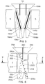
- FIG. 5 illustrates another embodiment of the invention in which a second array 114B of ferromagnetic rods 152B is rotated 180° about the vertical axis of the gap between the pole pieces and is mounted adjacent to the pole face opposite to the basic array 114A.
- Three input channels 156A, 156B, and 158 and three associated discharge channels 156Aa, 156Ba, and 158a, located substantially below the respective input channels, are provided in the embodiment of FIG. 5.
- the two outer input channels 156A and 156B are material input channels and the center channel 158 is a liquid input channel. As shown in FIG.
- the left-hand array 114A of rods 152A extends between the input channel 156A and the discharge channel 156Aa
- the right-hand array 114B of rods extends between the input channel 156B and the discharge channel 156Ba
- both arrays 114A and 114B are inclined towards the center exit channel 158a.
- the two outer discharge channels 156Aa and 156Ba receive the nonmagnetic particles from the material fed into the input channels 156A and 156B, respectively.
- the magnetic particles from both input channels 156A and 156B are received by the central discharge channel 158a.
- FIG. 6 illustrates a third embodiment of the invention in which an array 214 of triangular ferromagnetic plates 252 is provided instead of rods.
- the separator also comprises a material feed channel 256, a nonmagnetic fraction discharge channel 256a, a liquid supply channel 258 and a magnetic fraction discharge channel 258a.
- the feed channel 256 and the nonmagnetic discharge channel 256a connect to form channel 257.
- a divider 260 is placed between the feed channel and the liquid supply channel, extending into the separation chamber to a position such that it guides the wash liquid to encounter the deflected magnetic material where separation begins to take place.
- each plate 252 is near the upper end of the separation chamber into which material is fed.
- the junction between the front edge 252b and the base edge 252c of the triangle is near the lower end of the separation chamber and near the discharge channel 258a for magnetic particles.
- the front edge 252b of each plate is on the same side of a common plane A'-A' which is oriented at an angle substantially perpendicular to the magnetic field direction and at an acute angle to a vertical line from the feed channel 256 to the discharge channel 256a for nonmagnetic particles.
- the front edge 252b of each plate is rounded off in cross section, as is shown in FIG. 7.
- each plate at the apex 252a and at the junction with the base edge 252b is shaped to form a second order convex curve having a suitable radius (>3/8 inch and preferably >1/2 inch).
- the front edge 252b at the junction with the base edge 252c may be shaped to form an isodynamic curve.
- the shape of an isodynamic curve is described in detail in U.S. Patent No. 2,056,426 to S. G. Frantz, which is hereby incorporated by reference.
- a nonmagnetic member 254 is fitted to the front edge of each triangular plate 252, the inner walls of such members 254 forming a channel equal in width to or narrower than the space between the plates.
- the triangular plates 252 are joined by and form an integral whole with a back plate 255.
- the separate nonmagnetic separation chamber 12, 112 shown in FIGS. 1, 2 and 5 is omitted and the outer surfaces of the outermost plates 252 (only two are shown in FIG. 7) and the outer surfaces of the nonmagnetic members 254 form the walls of the separation chamber.
- a thin nonmagnetic shield 253 is affixed to the inner surface of the back plate 255 in the spaces between the plates 252.
- the back plate sections 355 between plates 352 may take the shape of a second-order concave curve in cross section.
- the width of the array of triangular plates 352 may be substantially equal to the width of the pole pieces.
- FIG. 9 illustrates a fourth embodiment of the invention, in which a second array 414B of triangular plates 452B similar to the array 214 shown in FIGS. 6 and 7, rotated 180° about the horizontal axis parallel to the pole faces passing through the center of the gap, is mounted adjacent to the pole face opposite to the basic array 414A.
- the separator also comprises a feed channel 456, a nonmagnetic fraction discharge channel 456a, a liquid supply channel 458 and a magnetic fraction discharge channel 458a.
- the feed channel 456 and the nonmagnetic fraction discharge channel 456a connect to form a channel 457.
- a nonmagnetic member 454 is fitted to the front edge of each plate of the arrays 414A and 414B.
- the inner surfaces of the members 454 form a channel equal in width or narrower than the space between the plates.
- the triangular plates of each array 452A, 452B are joined by and form an integral whole with back plates 455A, 455B.
- Thin nonmagnetic shields 453 may be affixed to the back plate between plates.
- the arrays of plates 552A and 552B have a width equal to the pole pieces.
- FIG. 12 illustrates a fifth embodiment of the invention, in which three arrays 614A, 614B, 614C of triangular ferromagnetic plates 652A, 652B, 652C are provided, the first array 614A being similar in shape to the basic array 214 shown in FIG. 6, but rotated 180° about the horizontal axis parallel to field direction so that the base edge 652Ac of each plate of the first array is near the material feed end of the separation chamber and its front edge 652Ab extends downward and outward towards the left hand poleface, joining the back plate 655A at the opposite end of the chamber.
- the second array 614B is similar in shape and position to the right hand array 414B shown in FIG. 9.
- the third array 614C consisting of plates shaped as isosceles triangles, is placed between the first and second arrays.
- the isosceles edges 652Ca, 652Cb of each plate of the third array are fitted with nonmagnetic members 654 forming a channel equal in width to or narrower than the space between the plates, and extending the edges so that they converge to a point at the apex 654a.
- the separator also comprises a feed channel 656, a nonmagnetic particle discharge channel 656a, two liquid supply channels 658A, 658B and two magnetic particle discharge channels 658Aa, 658Ba.
- FIG. 13 illustrates a sixth embodiment of the invention, in which the three arrays 714A, 714B, 714C of triangular ferromagnetic plates similar in shape to those shown in FIG. 12 are rotated 180° about the horizontal axis parallel to field direction so that the apex 752Aa, 752Ba of each plate of the first and second arrays is near the upper end of the separating chamber and the apex 754a of the nonmagnetic members attached to the third array is inverted and near the opposite or lower end of the chamber.
- the separator also comprises two feed channels 756A, 756B separated by dividers 760A, 760B between them and a liquid supply channel 758, two nonmagnetic particle discharge channels 756Aa, 756Ba, and a magnetic particle discharge channel 758a.
- FIGS. 12 and 13 have in common that in each the plates of the third array are joined together at the vertical axis by ferromagnetic bars 662, 762 which preferably form an integral whole therewith, that the plates of the three arrays and the spaces between them are aligned, and that nonmagnetic members fitted to the front edges of the first and second arrays are aligned with the nonmagnetic members fitted to the isosceles edges of the third array.
- the method and apparatus can be modified so as to be suitable for separation of dry materials moved in a vacuum or a gaseous medium, or apparatus can be disposed so as to be suitable for separating material fed upwards or in any other direction.
- the pole pieces may be omitted in magnetic systems, such as super conducting magnetic systems, in which they are not required to generate the magnetic field. All such modifications and variations, therefore, are intended to be encompassed within the spirit and scope of the appended claims.
- Magnetic separations are made by feeding material to a magnetic separator having elongated ferromagnetic bodies that are disposed parallel to each other with spaces therebetween, the bodies being disposed at an angle to the magnetic field direction.
- the magnetic particles are deflected away, while the nonmagnetic particles pass through the spaces between the ferromagnetic bodies.
- the separator includes a magnetic circuit including an array of elongated ferromagnetic bodies, parallel to each other with spaces therebetween, and on the same side of a common tangential plane that is positioned at an angle to the direction of the field created by the magnetic system.
- the separator also includes a material feeder, means for collecting nonmagnetic product mounted on the opposite side of the common tangential plane array, means for collecting magnetic product, and liquid supply means separated from the feeder by a divider extending into the separation chamber. To enhance separation, a separate stream of clean liquid is introduced into the separation chamber so that it encounters the stream of material undergoing separation.
Landscapes
- Physical Or Chemical Processes And Apparatus (AREA)
- Separation Of Solids By Using Liquids Or Pneumatic Power (AREA)
- Water Treatment By Electricity Or Magnetism (AREA)
Applications Claiming Priority (2)
| Application Number | Priority Date | Filing Date | Title |
|---|---|---|---|
| US08/349,896 US5568869A (en) | 1994-12-06 | 1994-12-06 | Methods and apparatus for making continuous magnetic separations |
| US349896 | 1994-12-06 |
Publications (3)
| Publication Number | Publication Date |
|---|---|
| EP0718037A2 true EP0718037A2 (de) | 1996-06-26 |
| EP0718037A3 EP0718037A3 (de) | 1997-11-19 |
| EP0718037B1 EP0718037B1 (de) | 2000-03-08 |
Family
ID=23374431
Family Applications (1)
| Application Number | Title | Priority Date | Filing Date |
|---|---|---|---|
| EP94120350A Expired - Lifetime EP0718037B1 (de) | 1994-12-06 | 1994-12-21 | Verfahren und Vorrichtung zur Verwirklichung einer kontinuierlichen magnetischen Trennung |
Country Status (7)
| Country | Link |
|---|---|
| US (1) | US5568869A (de) |
| EP (1) | EP0718037B1 (de) |
| AU (1) | AU680067B2 (de) |
| CA (1) | CA2138340C (de) |
| DE (1) | DE69423359T2 (de) |
| FI (1) | FI107781B (de) |
| ZA (1) | ZA9410353B (de) |
Cited By (2)
| Publication number | Priority date | Publication date | Assignee | Title |
|---|---|---|---|---|
| EP1661625A1 (de) * | 2002-01-23 | 2006-05-31 | F.Hoffmann-La Roche Ag | Apparat zum Zurückhalten von Magnetteilchen in einer von einer Flüssigkeit durchströmten Zelle |
| EP2368639A1 (de) * | 2010-03-23 | 2011-09-28 | Siemens Aktiengesellschaft | Vorrichtung und Verfahren zur Magnetseparation eines Fluids |
Families Citing this family (16)
| Publication number | Priority date | Publication date | Assignee | Title |
|---|---|---|---|---|
| US6120735A (en) * | 1992-02-26 | 2000-09-19 | The Ohio States University | Fractional cell sorter |
| US5909813A (en) * | 1997-01-13 | 1999-06-08 | Lift Feeder Inc. | Force field separator |
| US5968820A (en) * | 1997-02-26 | 1999-10-19 | The Cleveland Clinic Foundation | Method for magnetically separating cells into fractionated flow streams |
| EP1224023B1 (de) | 1999-09-03 | 2005-05-18 | The Cleveland Clinic Foundation | Kontinuierliche trennung von molekülen und teilchen mittels eines ringförmigen strömungskanals |
| US6210572B1 (en) | 1999-10-18 | 2001-04-03 | Technology Commercialization Corp. | Filter and method for purifying liquids containing magnetic particles |
| RU2209684C2 (ru) * | 2000-08-29 | 2003-08-10 | Александр Михайлович Туркенич | Способ непрерывной магнитной сепарации слабомагнитных материалов и устройство для его осуществления |
| RU2185247C1 (ru) * | 2001-10-18 | 2002-07-20 | Стафеев Алексей Алексеевич | Магнитный гидросепаратор |
| RU2263547C1 (ru) * | 2004-05-12 | 2005-11-10 | Научно-Производственная Фирма "Продэкология" | Способ магнитной сепарации слабомагнитных материалов и устройство для его осуществления |
| US20050274650A1 (en) * | 2004-06-09 | 2005-12-15 | Georgia Tech Research Corporation | Blood separation systems in micro device format and fabrication methods |
| US7473407B2 (en) * | 2004-11-19 | 2009-01-06 | Solvay Chemicals | Magnetic separation process for trona |
| AU2009299101B2 (en) * | 2008-10-01 | 2011-10-06 | Robert Hume Pannell | Electro-magnetic flux clarifier, thickener or separator |
| US8292084B2 (en) | 2009-10-28 | 2012-10-23 | Magnetation, Inc. | Magnetic separator |
| WO2012145658A1 (en) | 2011-04-20 | 2012-10-26 | Magnetation, Inc. | Iron ore separation device |
| CN108296017A (zh) * | 2018-01-31 | 2018-07-20 | 安徽世界村新材料有限公司 | 一种废橡胶自动化连续高效磁选装置及磁选方法 |
| JP6446631B1 (ja) * | 2018-02-07 | 2019-01-09 | 株式会社Jmc | 棒状磁石及び磁性異物除去装置 |
| CN118663414B (zh) * | 2024-08-23 | 2024-11-05 | 连云港取道石英制品有限公司 | 一种石英砂生产用除杂磁选装置 |
Family Cites Families (7)
| Publication number | Priority date | Publication date | Assignee | Title |
|---|---|---|---|---|
| US2056426A (en) * | 1932-05-31 | 1936-10-06 | Frantz Samuel Gibson | Magnetic separation method and means |
| US4235710A (en) * | 1978-07-03 | 1980-11-25 | S. G. Frantz Company, Inc. | Methods and apparatus for separating particles using a magnetic barrier |
| US4261815A (en) * | 1979-12-31 | 1981-04-14 | Massachusetts Institute Of Technology | Magnetic separator and method |
| GB2157195B (en) * | 1984-03-28 | 1987-08-26 | Cryogenic Consult | Magnetic separators |
| US4663029A (en) * | 1985-04-08 | 1987-05-05 | Massachusetts Institute Of Technology | Method and apparatus for continuous magnetic separation |
| GB8530361D0 (en) * | 1985-12-10 | 1986-01-22 | Gec Elliott Mech Handling | Magnetic separators |
| DE3610303C1 (de) * | 1986-03-26 | 1987-02-19 | Schoenert Klaus Prof Dr Ing | Verfahren und Vorrichtungen zur Sortierung paramagnetischer Partikeln im Fein- und Feinstkornbereich in einem magnetischen Starkfeld |
-
1994
- 1994-12-06 US US08/349,896 patent/US5568869A/en not_active Expired - Fee Related
- 1994-12-16 CA CA002138340A patent/CA2138340C/en not_active Expired - Fee Related
- 1994-12-20 FI FI945973A patent/FI107781B/fi active
- 1994-12-20 AU AU81576/94A patent/AU680067B2/en not_active Ceased
- 1994-12-21 EP EP94120350A patent/EP0718037B1/de not_active Expired - Lifetime
- 1994-12-21 DE DE69423359T patent/DE69423359T2/de not_active Expired - Fee Related
- 1994-12-28 ZA ZA9410353A patent/ZA9410353B/xx unknown
Cited By (9)
| Publication number | Priority date | Publication date | Assignee | Title |
|---|---|---|---|---|
| EP1661625A1 (de) * | 2002-01-23 | 2006-05-31 | F.Hoffmann-La Roche Ag | Apparat zum Zurückhalten von Magnetteilchen in einer von einer Flüssigkeit durchströmten Zelle |
| US7601265B2 (en) | 2002-01-23 | 2009-10-13 | Roche Molecular Systems, Inc. | Apparatus for retaining magnetic particles within a flow-through cell |
| EP2368639A1 (de) * | 2010-03-23 | 2011-09-28 | Siemens Aktiengesellschaft | Vorrichtung und Verfahren zur Magnetseparation eines Fluids |
| WO2011117039A1 (de) * | 2010-03-23 | 2011-09-29 | Siemens Aktiengesellschaft | Vorrichtung und verfahren zur magnetseparation eines fluids |
| CN102933308A (zh) * | 2010-03-23 | 2013-02-13 | 西门子公司 | 用于使流体磁性分离的装置和方法 |
| AU2011231885B2 (en) * | 2010-03-23 | 2014-04-17 | Siemens Aktiengesellschaft | Device and method for the magnetic separation of a fluid |
| US8844730B2 (en) | 2010-03-23 | 2014-09-30 | Siemens Aktiengesellschaft | Device and method for magnetic separation of a fluid |
| RU2544933C2 (ru) * | 2010-03-23 | 2015-03-20 | Сименс Акциенгезелльшафт | Устройство и способ для магнитного разделения текучей среды |
| CN102933308B (zh) * | 2010-03-23 | 2015-09-16 | 西门子公司 | 用于使流体磁性分离的装置和方法 |
Also Published As
| Publication number | Publication date |
|---|---|
| DE69423359T2 (de) | 2000-07-27 |
| CA2138340C (en) | 1999-01-19 |
| ZA9410353B (en) | 1995-09-05 |
| FI945973A7 (fi) | 1996-06-07 |
| CA2138340A1 (en) | 1996-06-07 |
| AU680067B2 (en) | 1997-07-17 |
| FI107781B (fi) | 2001-10-15 |
| FI945973A0 (fi) | 1994-12-20 |
| DE69423359D1 (de) | 2000-04-13 |
| US5568869A (en) | 1996-10-29 |
| EP0718037B1 (de) | 2000-03-08 |
| AU8157694A (en) | 1996-06-13 |
| EP0718037A3 (de) | 1997-11-19 |
Similar Documents
| Publication | Publication Date | Title |
|---|---|---|
| EP0718037B1 (de) | Verfahren und Vorrichtung zur Verwirklichung einer kontinuierlichen magnetischen Trennung | |
| US4565624A (en) | Gravity--magnetic ore separators | |
| US7105041B2 (en) | Grid type electrostatic separator/collector and method of using same | |
| AU601729B2 (en) | Process and device for sorting of paramagnetic particles in the fine and very fine grain range in a strongly magnetic field | |
| JP2002511337A (ja) | 流体の流れの中で微粒子を操作する方法および装置 | |
| CA2285085A1 (en) | Fractional cell sorter | |
| CA1074261A (en) | Density classifier using ferro-paramagnetic slurry medium | |
| US20090071328A1 (en) | Grid type electrostatic separator/collector and method of using same | |
| US6390302B1 (en) | Method and apparatus for separating particles | |
| US4659457A (en) | Gravity-magnetic ore separators and methods | |
| US2979202A (en) | Magnetic baffle separator | |
| US4214984A (en) | Magnetic separation | |
| US2789658A (en) | Apparatus for collecting suspended particles | |
| HK1010349A (en) | Methods and apparatus for making continuous magnetic separations | |
| US5909813A (en) | Force field separator | |
| WO2000025929A1 (en) | Magnetic separation method and apparatus | |
| RU2103072C1 (ru) | Способ непрерывной магнитной сепарации слабомагнитных материалов и устройство для его осуществления | |
| RU2246358C1 (ru) | Магнитный сепаратор-анализатор | |
| GB2217632A (en) | Magnetic separator | |
| JPS58104645A (ja) | 連続型高勾配磁力選別装置 | |
| US20210213449A1 (en) | Dielectrophoresis and density separators | |
| AU605232B2 (en) | Improvements in and relating to magnetic separators | |
| SU1740069A1 (ru) | Матрица высокоградиентного электромагнитного сепаратора | |
| CN223171065U (zh) | 一种磁铁矿线形磁团聚柱式分选设备 | |
| Cohen et al. | The application of a superconducting magnet system to the cleaning and desulphurization of coal |
Legal Events
| Date | Code | Title | Description |
|---|---|---|---|
| PUAI | Public reference made under article 153(3) epc to a published international application that has entered the european phase |
Free format text: ORIGINAL CODE: 0009012 |
|
| AK | Designated contracting states |
Kind code of ref document: A2 Designated state(s): DE GB SE |
|
| PUAL | Search report despatched |
Free format text: ORIGINAL CODE: 0009013 |
|
| AK | Designated contracting states |
Kind code of ref document: A3 Designated state(s): DE GB SE |
|
| RHK1 | Main classification (correction) |
Ipc: B03C 1/035 |
|
| 17P | Request for examination filed |
Effective date: 19980305 |
|
| 17Q | First examination report despatched |
Effective date: 19981125 |
|
| GRAG | Despatch of communication of intention to grant |
Free format text: ORIGINAL CODE: EPIDOS AGRA |
|
| GRAG | Despatch of communication of intention to grant |
Free format text: ORIGINAL CODE: EPIDOS AGRA |
|
| GRAH | Despatch of communication of intention to grant a patent |
Free format text: ORIGINAL CODE: EPIDOS IGRA |
|
| GRAH | Despatch of communication of intention to grant a patent |
Free format text: ORIGINAL CODE: EPIDOS IGRA |
|
| GRAA | (expected) grant |
Free format text: ORIGINAL CODE: 0009210 |
|
| AK | Designated contracting states |
Kind code of ref document: B1 Designated state(s): DE GB SE |
|
| PG25 | Lapsed in a contracting state [announced via postgrant information from national office to epo] |
Ref country code: SE Free format text: THE PATENT HAS BEEN ANNULLED BY A DECISION OF A NATIONAL AUTHORITY Effective date: 20000308 |
|
| REF | Corresponds to: |
Ref document number: 69423359 Country of ref document: DE Date of ref document: 20000413 |
|
| EN | Fr: translation not filed | ||
| PLBE | No opposition filed within time limit |
Free format text: ORIGINAL CODE: 0009261 |
|
| STAA | Information on the status of an ep patent application or granted ep patent |
Free format text: STATUS: NO OPPOSITION FILED WITHIN TIME LIMIT |
|
| 26N | No opposition filed | ||
| REG | Reference to a national code |
Ref country code: GB Ref legal event code: IF02 |
|
| PGFP | Annual fee paid to national office [announced via postgrant information from national office to epo] |
Ref country code: GB Payment date: 20021218 Year of fee payment: 9 |
|
| PGFP | Annual fee paid to national office [announced via postgrant information from national office to epo] |
Ref country code: DE Payment date: 20021230 Year of fee payment: 9 |
|
| PG25 | Lapsed in a contracting state [announced via postgrant information from national office to epo] |
Ref country code: GB Free format text: LAPSE BECAUSE OF NON-PAYMENT OF DUE FEES Effective date: 20031221 |
|
| PG25 | Lapsed in a contracting state [announced via postgrant information from national office to epo] |
Ref country code: DE Free format text: LAPSE BECAUSE OF NON-PAYMENT OF DUE FEES Effective date: 20040701 |
|
| GBPC | Gb: european patent ceased through non-payment of renewal fee |
Effective date: 20031221 |
|
| REG | Reference to a national code |
Ref country code: HK Ref legal event code: WD Ref document number: 1010349 Country of ref document: HK |