EP0718068A1 - Méthode pour le soudage d'éléments différents - Google Patents
Méthode pour le soudage d'éléments différents Download PDFInfo
- Publication number
- EP0718068A1 EP0718068A1 EP95120045A EP95120045A EP0718068A1 EP 0718068 A1 EP0718068 A1 EP 0718068A1 EP 95120045 A EP95120045 A EP 95120045A EP 95120045 A EP95120045 A EP 95120045A EP 0718068 A1 EP0718068 A1 EP 0718068A1
- Authority
- EP
- European Patent Office
- Prior art keywords
- welded
- welding
- insert
- cups
- inserts
- Prior art date
- Legal status (The legal status is an assumption and is not a legal conclusion. Google has not performed a legal analysis and makes no representation as to the accuracy of the status listed.)
- Granted
Links
Images
Classifications
-
- B—PERFORMING OPERATIONS; TRANSPORTING
- B62—LAND VEHICLES FOR TRAVELLING OTHERWISE THAN ON RAILS
- B62D—MOTOR VEHICLES; TRAILERS
- B62D29/00—Superstructures, understructures, or sub-units thereof, characterised by the material thereof
- B62D29/001—Superstructures, understructures, or sub-units thereof, characterised by the material thereof characterised by combining metal and synthetic material
-
- B—PERFORMING OPERATIONS; TRANSPORTING
- B23—MACHINE TOOLS; METAL-WORKING NOT OTHERWISE PROVIDED FOR
- B23K—SOLDERING OR UNSOLDERING; WELDING; CLADDING OR PLATING BY SOLDERING OR WELDING; CUTTING BY APPLYING HEAT LOCALLY, e.g. FLAME CUTTING; WORKING BY LASER BEAM
- B23K11/00—Resistance welding; Severing by resistance heating
- B23K11/10—Spot welding; Stitch welding
- B23K11/11—Spot welding
-
- B—PERFORMING OPERATIONS; TRANSPORTING
- B29—WORKING OF PLASTICS; WORKING OF SUBSTANCES IN A PLASTIC STATE IN GENERAL
- B29C—SHAPING OR JOINING OF PLASTICS; SHAPING OF MATERIAL IN A PLASTIC STATE, NOT OTHERWISE PROVIDED FOR; AFTER-TREATMENT OF THE SHAPED PRODUCTS, e.g. REPAIRING
- B29C65/00—Joining or sealing of preformed parts, e.g. welding of plastics materials; Apparatus therefor
- B29C65/56—Joining or sealing of preformed parts, e.g. welding of plastics materials; Apparatus therefor using mechanical means or mechanical connections, e.g. form-fits
- B29C65/562—Joining or sealing of preformed parts, e.g. welding of plastics materials; Apparatus therefor using mechanical means or mechanical connections, e.g. form-fits using extra joining elements, i.e. which are not integral with the parts to be joined
-
- B—PERFORMING OPERATIONS; TRANSPORTING
- B29—WORKING OF PLASTICS; WORKING OF SUBSTANCES IN A PLASTIC STATE IN GENERAL
- B29C—SHAPING OR JOINING OF PLASTICS; SHAPING OF MATERIAL IN A PLASTIC STATE, NOT OTHERWISE PROVIDED FOR; AFTER-TREATMENT OF THE SHAPED PRODUCTS, e.g. REPAIRING
- B29C65/00—Joining or sealing of preformed parts, e.g. welding of plastics materials; Apparatus therefor
- B29C65/56—Joining or sealing of preformed parts, e.g. welding of plastics materials; Apparatus therefor using mechanical means or mechanical connections, e.g. form-fits
- B29C65/64—Joining a non-plastics element to a plastics element, e.g. by force
-
- B—PERFORMING OPERATIONS; TRANSPORTING
- B29—WORKING OF PLASTICS; WORKING OF SUBSTANCES IN A PLASTIC STATE IN GENERAL
- B29C—SHAPING OR JOINING OF PLASTICS; SHAPING OF MATERIAL IN A PLASTIC STATE, NOT OTHERWISE PROVIDED FOR; AFTER-TREATMENT OF THE SHAPED PRODUCTS, e.g. REPAIRING
- B29C66/00—General aspects of processes or apparatus for joining preformed parts
- B29C66/01—General aspects dealing with the joint area or with the area to be joined
- B29C66/05—Particular design of joint configurations
- B29C66/10—Particular design of joint configurations particular design of the joint cross-sections
- B29C66/11—Joint cross-sections comprising a single joint-segment, i.e. one of the parts to be joined comprising a single joint-segment in the joint cross-section
- B29C66/112—Single lapped joints
- B29C66/1122—Single lap to lap joints, i.e. overlap joints
-
- B—PERFORMING OPERATIONS; TRANSPORTING
- B29—WORKING OF PLASTICS; WORKING OF SUBSTANCES IN A PLASTIC STATE IN GENERAL
- B29C—SHAPING OR JOINING OF PLASTICS; SHAPING OF MATERIAL IN A PLASTIC STATE, NOT OTHERWISE PROVIDED FOR; AFTER-TREATMENT OF THE SHAPED PRODUCTS, e.g. REPAIRING
- B29C66/00—General aspects of processes or apparatus for joining preformed parts
- B29C66/01—General aspects dealing with the joint area or with the area to be joined
- B29C66/05—Particular design of joint configurations
- B29C66/20—Particular design of joint configurations particular design of the joint lines, e.g. of the weld lines
- B29C66/21—Particular design of joint configurations particular design of the joint lines, e.g. of the weld lines said joint lines being formed by a single dot or dash or by several dots or dashes, i.e. spot joining or spot welding
-
- B—PERFORMING OPERATIONS; TRANSPORTING
- B29—WORKING OF PLASTICS; WORKING OF SUBSTANCES IN A PLASTIC STATE IN GENERAL
- B29C—SHAPING OR JOINING OF PLASTICS; SHAPING OF MATERIAL IN A PLASTIC STATE, NOT OTHERWISE PROVIDED FOR; AFTER-TREATMENT OF THE SHAPED PRODUCTS, e.g. REPAIRING
- B29C66/00—General aspects of processes or apparatus for joining preformed parts
- B29C66/70—General aspects of processes or apparatus for joining preformed parts characterised by the composition, physical properties or the structure of the material of the parts to be joined; Joining with non-plastics material
- B29C66/74—Joining plastics material to non-plastics material
- B29C66/742—Joining plastics material to non-plastics material to metals or their alloys
-
- B—PERFORMING OPERATIONS; TRANSPORTING
- B62—LAND VEHICLES FOR TRAVELLING OTHERWISE THAN ON RAILS
- B62D—MOTOR VEHICLES; TRAILERS
- B62D29/00—Superstructures, understructures, or sub-units thereof, characterised by the material thereof
- B62D29/001—Superstructures, understructures, or sub-units thereof, characterised by the material thereof characterised by combining metal and synthetic material
- B62D29/004—Superstructures, understructures, or sub-units thereof, characterised by the material thereof characterised by combining metal and synthetic material the metal being over-moulded by the synthetic material, e.g. in a mould
-
- B—PERFORMING OPERATIONS; TRANSPORTING
- B23—MACHINE TOOLS; METAL-WORKING NOT OTHERWISE PROVIDED FOR
- B23K—SOLDERING OR UNSOLDERING; WELDING; CLADDING OR PLATING BY SOLDERING OR WELDING; CUTTING BY APPLYING HEAT LOCALLY, e.g. FLAME CUTTING; WORKING BY LASER BEAM
- B23K2103/00—Materials to be soldered, welded or cut
- B23K2103/08—Non-ferrous metals or alloys
- B23K2103/10—Aluminium or alloys thereof
-
- B—PERFORMING OPERATIONS; TRANSPORTING
- B23—MACHINE TOOLS; METAL-WORKING NOT OTHERWISE PROVIDED FOR
- B23K—SOLDERING OR UNSOLDERING; WELDING; CLADDING OR PLATING BY SOLDERING OR WELDING; CUTTING BY APPLYING HEAT LOCALLY, e.g. FLAME CUTTING; WORKING BY LASER BEAM
- B23K2103/00—Materials to be soldered, welded or cut
- B23K2103/18—Dissimilar materials
-
- B—PERFORMING OPERATIONS; TRANSPORTING
- B23—MACHINE TOOLS; METAL-WORKING NOT OTHERWISE PROVIDED FOR
- B23K—SOLDERING OR UNSOLDERING; WELDING; CLADDING OR PLATING BY SOLDERING OR WELDING; CUTTING BY APPLYING HEAT LOCALLY, e.g. FLAME CUTTING; WORKING BY LASER BEAM
- B23K2103/00—Materials to be soldered, welded or cut
- B23K2103/18—Dissimilar materials
- B23K2103/20—Ferrous alloys and aluminium or alloys thereof
-
- B—PERFORMING OPERATIONS; TRANSPORTING
- B23—MACHINE TOOLS; METAL-WORKING NOT OTHERWISE PROVIDED FOR
- B23K—SOLDERING OR UNSOLDERING; WELDING; CLADDING OR PLATING BY SOLDERING OR WELDING; CUTTING BY APPLYING HEAT LOCALLY, e.g. FLAME CUTTING; WORKING BY LASER BEAM
- B23K2103/00—Materials to be soldered, welded or cut
- B23K2103/30—Organic materials
- B23K2103/42—Plastics other than composite materials
-
- B—PERFORMING OPERATIONS; TRANSPORTING
- B29—WORKING OF PLASTICS; WORKING OF SUBSTANCES IN A PLASTIC STATE IN GENERAL
- B29C—SHAPING OR JOINING OF PLASTICS; SHAPING OF MATERIAL IN A PLASTIC STATE, NOT OTHERWISE PROVIDED FOR; AFTER-TREATMENT OF THE SHAPED PRODUCTS, e.g. REPAIRING
- B29C66/00—General aspects of processes or apparatus for joining preformed parts
- B29C66/40—General aspects of joining substantially flat articles, e.g. plates, sheets or web-like materials; Making flat seams in tubular or hollow articles; Joining single elements to substantially flat surfaces
- B29C66/41—Joining substantially flat articles ; Making flat seams in tubular or hollow articles
-
- B—PERFORMING OPERATIONS; TRANSPORTING
- B29—WORKING OF PLASTICS; WORKING OF SUBSTANCES IN A PLASTIC STATE IN GENERAL
- B29C—SHAPING OR JOINING OF PLASTICS; SHAPING OF MATERIAL IN A PLASTIC STATE, NOT OTHERWISE PROVIDED FOR; AFTER-TREATMENT OF THE SHAPED PRODUCTS, e.g. REPAIRING
- B29C66/00—General aspects of processes or apparatus for joining preformed parts
- B29C66/50—General aspects of joining tubular articles; General aspects of joining long products, i.e. bars or profiled elements; General aspects of joining single elements to tubular articles, hollow articles or bars; General aspects of joining several hollow-preforms to form hollow or tubular articles
- B29C66/51—Joining tubular articles, profiled elements or bars; Joining single elements to tubular articles, hollow articles or bars; Joining several hollow-preforms to form hollow or tubular articles
- B29C66/54—Joining several hollow-preforms, e.g. half-shells, to form hollow articles, e.g. for making balls, containers; Joining several hollow-preforms, e.g. half-cylinders, to form tubular articles
-
- B—PERFORMING OPERATIONS; TRANSPORTING
- B29—WORKING OF PLASTICS; WORKING OF SUBSTANCES IN A PLASTIC STATE IN GENERAL
- B29C—SHAPING OR JOINING OF PLASTICS; SHAPING OF MATERIAL IN A PLASTIC STATE, NOT OTHERWISE PROVIDED FOR; AFTER-TREATMENT OF THE SHAPED PRODUCTS, e.g. REPAIRING
- B29C66/00—General aspects of processes or apparatus for joining preformed parts
- B29C66/70—General aspects of processes or apparatus for joining preformed parts characterised by the composition, physical properties or the structure of the material of the parts to be joined; Joining with non-plastics material
- B29C66/73—General aspects of processes or apparatus for joining preformed parts characterised by the composition, physical properties or the structure of the material of the parts to be joined; Joining with non-plastics material characterised by the intensive physical properties of the material of the parts to be joined, by the optical properties of the material of the parts to be joined, by the extensive physical properties of the parts to be joined, by the state of the material of the parts to be joined or by the material of the parts to be joined being a thermoplastic or a thermoset
- B29C66/731—General aspects of processes or apparatus for joining preformed parts characterised by the composition, physical properties or the structure of the material of the parts to be joined; Joining with non-plastics material characterised by the intensive physical properties of the material of the parts to be joined, by the optical properties of the material of the parts to be joined, by the extensive physical properties of the parts to be joined, by the state of the material of the parts to be joined or by the material of the parts to be joined being a thermoplastic or a thermoset characterised by the intensive physical properties of the material of the parts to be joined
- B29C66/7311—Thermal properties
- B29C66/73111—Thermal expansion coefficient
- B29C66/73112—Thermal expansion coefficient of different thermal expansion coefficient, i.e. the thermal expansion coefficient of one of the parts to be joined being different from the thermal expansion coefficient of the other part
-
- B—PERFORMING OPERATIONS; TRANSPORTING
- B29—WORKING OF PLASTICS; WORKING OF SUBSTANCES IN A PLASTIC STATE IN GENERAL
- B29C—SHAPING OR JOINING OF PLASTICS; SHAPING OF MATERIAL IN A PLASTIC STATE, NOT OTHERWISE PROVIDED FOR; AFTER-TREATMENT OF THE SHAPED PRODUCTS, e.g. REPAIRING
- B29C66/00—General aspects of processes or apparatus for joining preformed parts
- B29C66/80—General aspects of machine operations or constructions and parts thereof
- B29C66/83—General aspects of machine operations or constructions and parts thereof characterised by the movement of the joining or pressing tools
- B29C66/832—Reciprocating joining or pressing tools
- B29C66/8322—Joining or pressing tools reciprocating along one axis
- B29C66/83221—Joining or pressing tools reciprocating along one axis cooperating reciprocating tools, each tool reciprocating along one axis
-
- B—PERFORMING OPERATIONS; TRANSPORTING
- B29—WORKING OF PLASTICS; WORKING OF SUBSTANCES IN A PLASTIC STATE IN GENERAL
- B29L—INDEXING SCHEME ASSOCIATED WITH SUBCLASS B29C, RELATING TO PARTICULAR ARTICLES
- B29L2031/00—Other particular articles
- B29L2031/30—Vehicles, e.g. ships or aircraft, or body parts thereof
- B29L2031/3002—Superstructures characterized by combining metal and plastics, i.e. hybrid parts
Definitions
- the present invention relates to a method of connection by welding which makes it possible electrically to spot weld, for instance using the same apparatus that is used for sheet metal components, structural members formed from a material which may be identical or different.
- the object of the invention is to provide a method of connection by welding which makes it possible to assemble by welding, in particular using those electric spot welding methods that are currently known, bodywork members made from different materials, typically from steel and a synthetic plastic material.
- a further object of the invention is to provide a method of connection by welding which can be used to connect different members by electric spot welding without taking account of the material from which they are produced.
- the invention therefore provides a method of connection by welding, in particular by electric spot welding, of different members, characterised in that it comprises the following stages:
- these inserts are produced in the shape of cups of ferrous material sheet having internal dimensions that are greater than the dimensions of the welding guns used to carry out the actual welding operation, and having a flat base wall and, on the opposite side, axial shoulder means formed as flanges.
- inserts are preferably housed in the respective housings with a predetermined clearance and are permanently held in these by force fitting, by interposition between the insert and housing of a retaining member that can be elastically deformed, for instance in the form of an O-ring.
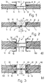
- Figs. 1 and 2 two different structural members to be connected together by welding are shown by 1 and 2; in particular, the members 1 and 2 are made from different materials: the member 1 is made from sheet steel and the member 2 from a stamped synthetic plastic material.
- the members 1 and 2 are preferably structural bodywork members of an automobile vehicle and may be of any shape and dimensions; the member 1 preferably forms part of an outer "skin" of the bodywork, while the plastic member 2 forms an internal framework thereof, which is to be connected to the member 1 along an ideal connection line 3, generally disposed so that it is not visible when the bodywork is assembled.
- connection along the line 3 is carried out by welding, in particular by electric spot welding carried out by known electrodes 4 of a known welding gun (not shown), in turn forming part of a known robot plant (not shown) for the assembly and welding of vehicle bodywork components.
- the method of the invention entails, in the first instance, the production on the plastic member 2, or on the member to be connected which is made from a material which cannot be welded by the electrodes 4, a plurality of housings 5 (Fig. 1), for instance formed by circular holes provided to pass through a portion 6 of the member 2 disposed along the planned connection line 3.
- housings 5 may be obtained directly together with the member 2, for instance by means of webs appropriately disposed in the mould during a stamping and injection stage thereof, or may be obtained afterwards by mechanical machining, for instance by drilling.
- the method of the invention also includes the production, for instance by cutting and stamping or using any other known method, of a plurality of inserts 8 adapted to be housed in the housings 6 and made from a metal sheet, in this case a sheet of ferrous material; in this way the inserts 8 are made from the same material (in the sense that ferro-carbon alloys, even if of different composition and/or with different additional alloying elements, are used in both cases) as the member 1 and in any case, from a material that can be readily welded therewith, in particular by electric spot welding.
- the inserts 8 are produced in the form of cylindrical cups obtained by drawing and cutting from a sheet of ferrous material so as to have internal dimensions greater than the dimensions of the respective welding guns 4 which may therefore be introduced into the concave sections of the cups 8, as shown.
- each cup 8 has a plane base wall 9 and, on the opposite side, respective axial shoulder means formed by an outer circular peripheral flange 10; the depth of drawing with which the cups 8 are produced is substantially equivalent to the depth of the housing 5 in which they are to be mounted (in this case equivalent to the thickness of the member 2).
- the method of connection by welding lastly comprises the subsequent stages of superimposed coupling of the portions 6 and 12 along the connection line 3, such that the surfaces 9 are facing one another and in contact with the sheet member 1; and of electric spot welding, in a known manner using the guns 4, of each insert (8) borne by the portion 6 (in this case its base wall 9) directly to the corresponding portion 12 of the member 1 coupled by superimposition on the portion 6.
- the wall 9 and the member 1, which are made from materials that are identical or at least compatible, are locally fused and generate a weld spot 20, which permanently ensures the connection of the insert 8 to the member 1; the member 2 is consequently permanently fastened to the member 1, both because it bears the rigid insert 8 and because it remains, after welding, packed between the portion 12 of the member 1 and the flange 10 of the insert 8 (Fig. 2) which now forms a single body with the member 1.
- the inserts 8 are normally made from sheet steel and the members 2 instead from a plastic material, i.e. from two materials which have substantially different coefficients of thermal expansion, there could be, in use, when assembly and welding is complete, differential thermal expansions which could generate internal stresses likely to weaken the connection obtained in the long term.
- the inserts 8, according to a further characteristic feature of the method of the invention are housed in the respective housings 5 with a predetermined lateral clearance 21 (Fig. 2) able to allow these differential thermal expansions; the force fitting of the inserts 8 in the housings 5 is therefore carried out, according to the invention, by interposing an elastically deformable retention member 30 between the insert 8 and the housing 5.
- the member 30 is formed by an O-ring of known type, housed in an annular groove 31 provided within the housing 5 on the side opposite to the surface 11, in a position such that it remains, when the insert 8 is inserted into the housing 5, facing the flanged shoulder means 10 borne by the insert 8.
- the O-ring 30 remains covered and protected by the flange 10 and axially contained between the latter and the base wall of the groove 31; this has a stepped shape, so as to contain the O-ring 30 peripherally as well, on the exterior thereof; the O-ring 30 may therefore exert its elasticity only towards the lateral wall of the cup 8 on which it is fitted in contact and which is not, vice versa, in contact with the lateral wall of the housing 5, as a result of the clearance 21.
- Fig. 3 shows the same two stages as Figs. 1 and 2, but in the case in which the members to be joined are a member 2 and, in place of the sheet member 1, a member 100 possibly made from a material which cannot be electrically spot welded, for instance a synthetic plastic material whose chemical nature is identical to or possibly completely different from that forming the member 2.
- both the members to be welded are provided with housings 5 provided along the connection line 3 of the respective portions 6 and 12, and both bear, housed rigidly within these housings 5, a plurality of identical inserts 8 formed by cups of ferrous alloy sheet, in particular in the same way as illustrated above, or inserted into the housings 5 with a lateral clearance 21 and held elastically force fitted therein by O-rings 30 housed in respective grooves 31 of the housings 5 and contained therein by the flanges 10.
- the cups 8 are mounted in corresponding positions on the portions 6 and 12, with the base walls 9 respectively on the edge of opposite surfaces 11 and 110 of the members 2 and 100, adapted to come into contact in use with portions 6 and 12 coupled by superimposition. Consequently, as the only difference from what has been described above, during the welding stage the inserts 8 of the member 2 are welded electrically by a spot weld 20 to the inserts 8 of the member 100, rather than directly on the latter; the spots 20 are formed by reciprocally joining the opposite base walls 9 of the inserts 8 brought into a corresponding position by the members 2 and 100 which, on the basis of what has been described, are in direct contact with one another. The result is therefore to connect the members 2 and 100, since both remain packed between the opposite flanges 10 of the opposite cups 8 disposed in a corresponding position and are made rigid by the respective spots 20.
- the material used for the cups 8 of the member 100 may also differ from the material used for the cups 8 of the member 2, formed by instance from any metal alloy, provided that it can be readily welded by means of the electrodes 4 to the material of the cups 8 of the member 2. It is also evident that, while the method of the invention is adapted for the production of vehicle bodyworks having a plastic framework and an outer skin of sheet steel, using those welding lines currently used for bodyworks made entirely from metal, this method may also be used to connect any members using welding techniques other than electric spot welding, for instance laser welding, etc.
- the method of the invention may also be used to connect parts of plastics of different chemical composition, which cannot be welded using welding techniques for known plastic materials (ultrasound, hot blade, etc.), in this case producing the inserts 8 also from a plastic material, but in this case of a chemical composition such that the inserts 8 can be welded together (or with one of the members to be welded) using the above-mentioned techniques.
Landscapes
- Engineering & Computer Science (AREA)
- Mechanical Engineering (AREA)
- Architecture (AREA)
- Structural Engineering (AREA)
- Chemical & Material Sciences (AREA)
- Combustion & Propulsion (AREA)
- Transportation (AREA)
- Resistance Welding (AREA)
- Lining Or Joining Of Plastics Or The Like (AREA)
Applications Claiming Priority (2)
| Application Number | Priority Date | Filing Date | Title |
|---|---|---|---|
| ITTO941067 | 1994-12-23 | ||
| IT94TO001067A IT1267357B1 (it) | 1994-12-23 | 1994-12-23 | Metodo di unione per saldatura tra elementi diversi. |
Publications (2)
| Publication Number | Publication Date |
|---|---|
| EP0718068A1 true EP0718068A1 (fr) | 1996-06-26 |
| EP0718068B1 EP0718068B1 (fr) | 1999-04-21 |
Family
ID=11413005
Family Applications (1)
| Application Number | Title | Priority Date | Filing Date |
|---|---|---|---|
| EP95120045A Expired - Lifetime EP0718068B1 (fr) | 1994-12-23 | 1995-12-19 | Méthode pour le soudage d'éléments différents |
Country Status (3)
| Country | Link |
|---|---|
| EP (1) | EP0718068B1 (fr) |
| DE (1) | DE69509201T2 (fr) |
| IT (1) | IT1267357B1 (fr) |
Cited By (9)
| Publication number | Priority date | Publication date | Assignee | Title |
|---|---|---|---|---|
| EP0967044A3 (fr) * | 1998-06-25 | 2002-05-15 | Pierino Garnero | Procédé pour le soudage à résistance par point d'une première tôle en matériau non-soudable à une deuxième tôle en matériau non-soudable |
| FR2891324A1 (fr) * | 2005-09-26 | 2007-03-30 | Valeo Systemes Thermiques | Dispositif d'assemblage entre deux plaques stratifiees composees d'une couche de resine interposee entre deux toles metalliques |
| DE102010034183A1 (de) * | 2010-08-12 | 2012-02-16 | Edag Gmbh & Co. Kgaa | Verfahren zum Verbinden von Bauteilen |
| FR2999105A1 (fr) * | 2012-12-10 | 2014-06-13 | Faurecia Bloc Avant | Procede de realisation d'une piece hybride comprenant une partie metallique et une partie en materiau polymere |
| CN104551367A (zh) * | 2013-10-25 | 2015-04-29 | 理查德贝格纳连接技术有限公司及两合公司 | 具有安装件和焊接件的安装单元及制造安装单元的方法 |
| GB2558611A (en) * | 2017-01-10 | 2018-07-18 | Penn Engineering Fastening Tech Europe Ltd | A method of joining first and second components, a component assembly formed by the method and an insert for use in the component assembly |
| WO2019120755A1 (fr) * | 2017-12-21 | 2019-06-27 | Renault S.A.S | Pièce moulée polymère pour assemblage sur une armature métallique, et procédé de fabrication associé, d'une structure de caisse de véhicule automobile |
| CN111152466A (zh) * | 2020-01-20 | 2020-05-15 | 四达氟塑股份有限公司 | 一种氟塑料激光焊接用连接件及其使用方法 |
| GB2582766A (en) * | 2019-04-01 | 2020-10-07 | Unipart Powertrain Applications Ltd | Component with insert |
Families Citing this family (1)
| Publication number | Priority date | Publication date | Assignee | Title |
|---|---|---|---|---|
| DE102017212576B4 (de) * | 2017-07-21 | 2025-03-20 | Universität Stuttgart | Verbindung eines metallischen Bauteils und eines Kunststoff-Bauteils |
Citations (5)
| Publication number | Priority date | Publication date | Assignee | Title |
|---|---|---|---|---|
| FR1171051A (fr) * | 1957-04-10 | 1959-01-22 | Procédé d'assemblage tenace des feuilles en matières plastiques et autres matières soudables, avec des supports en toutes matières, et les produits résultant de lamise en oeuvre de ce procédé | |
| DE3210310A1 (de) * | 1982-03-20 | 1983-09-22 | Alfred Teves Gmbh, 6000 Frankfurt | Schweissverbindung zur befestigung eines kunststoffteiles an einem metallteil und verfahren zur herstellung der schweissverbindung |
| GB2119311A (en) * | 1982-04-27 | 1983-11-16 | Ford Motor Co | Composite components of sandwich construction |
| EP0173656A1 (fr) * | 1984-08-20 | 1986-03-05 | FIAT AUTO S.p.A. | Méthode et appareil de soudage de feuilles métalliques minces |
| EP0340094A2 (fr) * | 1988-04-27 | 1989-11-02 | Automobiles Peugeot | Procédé d'assemblage par rivetage d'une première pièce en matière plastique et d'une seconde pièce. |
-
1994
- 1994-12-23 IT IT94TO001067A patent/IT1267357B1/it active IP Right Grant
-
1995
- 1995-12-19 DE DE69509201T patent/DE69509201T2/de not_active Expired - Fee Related
- 1995-12-19 EP EP95120045A patent/EP0718068B1/fr not_active Expired - Lifetime
Patent Citations (5)
| Publication number | Priority date | Publication date | Assignee | Title |
|---|---|---|---|---|
| FR1171051A (fr) * | 1957-04-10 | 1959-01-22 | Procédé d'assemblage tenace des feuilles en matières plastiques et autres matières soudables, avec des supports en toutes matières, et les produits résultant de lamise en oeuvre de ce procédé | |
| DE3210310A1 (de) * | 1982-03-20 | 1983-09-22 | Alfred Teves Gmbh, 6000 Frankfurt | Schweissverbindung zur befestigung eines kunststoffteiles an einem metallteil und verfahren zur herstellung der schweissverbindung |
| GB2119311A (en) * | 1982-04-27 | 1983-11-16 | Ford Motor Co | Composite components of sandwich construction |
| EP0173656A1 (fr) * | 1984-08-20 | 1986-03-05 | FIAT AUTO S.p.A. | Méthode et appareil de soudage de feuilles métalliques minces |
| EP0340094A2 (fr) * | 1988-04-27 | 1989-11-02 | Automobiles Peugeot | Procédé d'assemblage par rivetage d'une première pièce en matière plastique et d'une seconde pièce. |
Cited By (13)
| Publication number | Priority date | Publication date | Assignee | Title |
|---|---|---|---|---|
| EP0967044A3 (fr) * | 1998-06-25 | 2002-05-15 | Pierino Garnero | Procédé pour le soudage à résistance par point d'une première tôle en matériau non-soudable à une deuxième tôle en matériau non-soudable |
| FR2891324A1 (fr) * | 2005-09-26 | 2007-03-30 | Valeo Systemes Thermiques | Dispositif d'assemblage entre deux plaques stratifiees composees d'une couche de resine interposee entre deux toles metalliques |
| EP1767792A3 (fr) * | 2005-09-26 | 2007-10-31 | Valeo Systèmes Thermiques | Dispositif d'assemblage entre deux plaques stratifiées composées d'une couche de résine interposée entre deux tôles métalliques |
| US7937816B2 (en) | 2005-09-26 | 2011-05-10 | Valeo Systemes Thermiques S.A.S. | Assembly device between two laminated panels consisting of a resin layer inserted between two metal sheets |
| DE102010034183A1 (de) * | 2010-08-12 | 2012-02-16 | Edag Gmbh & Co. Kgaa | Verfahren zum Verbinden von Bauteilen |
| FR2999105A1 (fr) * | 2012-12-10 | 2014-06-13 | Faurecia Bloc Avant | Procede de realisation d'une piece hybride comprenant une partie metallique et une partie en materiau polymere |
| CN104551367A (zh) * | 2013-10-25 | 2015-04-29 | 理查德贝格纳连接技术有限公司及两合公司 | 具有安装件和焊接件的安装单元及制造安装单元的方法 |
| US9744616B2 (en) | 2013-10-25 | 2017-08-29 | Richard Bergner VerbindungstechnikGmbH & Co. KG | Assembly unit with an assembly piece and a welding element, and method of producing the assembly unit |
| CN104551367B (zh) * | 2013-10-25 | 2018-04-10 | 理查德贝格纳连接技术有限公司及两合公司 | 具有安装件和焊接件的安装单元及制造安装单元的方法 |
| GB2558611A (en) * | 2017-01-10 | 2018-07-18 | Penn Engineering Fastening Tech Europe Ltd | A method of joining first and second components, a component assembly formed by the method and an insert for use in the component assembly |
| WO2019120755A1 (fr) * | 2017-12-21 | 2019-06-27 | Renault S.A.S | Pièce moulée polymère pour assemblage sur une armature métallique, et procédé de fabrication associé, d'une structure de caisse de véhicule automobile |
| GB2582766A (en) * | 2019-04-01 | 2020-10-07 | Unipart Powertrain Applications Ltd | Component with insert |
| CN111152466A (zh) * | 2020-01-20 | 2020-05-15 | 四达氟塑股份有限公司 | 一种氟塑料激光焊接用连接件及其使用方法 |
Also Published As
| Publication number | Publication date |
|---|---|
| ITTO941067A0 (it) | 1994-12-23 |
| EP0718068B1 (fr) | 1999-04-21 |
| DE69509201D1 (de) | 1999-05-27 |
| ITTO941067A1 (it) | 1996-06-23 |
| DE69509201T2 (de) | 1999-12-09 |
| IT1267357B1 (it) | 1997-01-28 |
Similar Documents
| Publication | Publication Date | Title |
|---|---|---|
| EP0718068B1 (fr) | Méthode pour le soudage d'éléments différents | |
| US10570951B2 (en) | Method for manufacture of a chassis module and chassis module manufactured according to such a method | |
| JP6619388B2 (ja) | 異材接合体の製造方法 | |
| EP1337429B1 (fr) | Structure de joint et procede de fabrication d'une structure de joint | |
| US7322106B2 (en) | Method of manufacturing a node for connecting vehicle frame members | |
| US20160158873A1 (en) | Method for connecting at least two sheet metal parts | |
| EP3437785B1 (fr) | Procédé de soudage laser | |
| EP3493943A1 (fr) | Articulation soudée hybride et son procédé de formation | |
| KR20040097369A (ko) | 아이빔 구조를 갖는 자동차 서스펜션 아암 | |
| EP3437786A1 (fr) | Structure de raccord | |
| CA2027238C (fr) | Methode d'assemblage | |
| US10196092B2 (en) | Structure for fixing motor vehicle roof module | |
| US11143227B2 (en) | Component combination of at least two components and a method for producing a component combination joined in a form-fitting and/or force-fitting manner | |
| US20190061032A1 (en) | System and method for joining structures of dissimilar material | |
| CN115523219A (zh) | 用于焊接式紧固件的保护盖以及使用盖保护的焊接式紧固件的焊接过程 | |
| US4751777A (en) | Method for making a full round bushing | |
| EP1293270A2 (fr) | Système d'essieu et procédé de fabrication d'un essieu | |
| US3975611A (en) | Trim fastening | |
| US8870369B2 (en) | Spectacles, device having a spectacles element and a hinge part, and method for fastening a hinge part to a spectacles element | |
| US6739789B2 (en) | Flanged ball pin and method for manufacturing thereof | |
| US20030116537A1 (en) | Fuel tank for a motor vehicle | |
| ES2105586T3 (es) | Metodo de soldadura laser de piezas embutidas con collarin de ensambladura. | |
| JP4030370B2 (ja) | 車両用ルーフ構造 | |
| CN110582650A (zh) | 接合体、汽车用座椅框架以及接合方法 | |
| US20040258855A1 (en) | Piece for placing against an element of bodywork, an element of bodywork suitable for receiving such a piece, and an assembly comprising such a piece and such an element of bodywork |
Legal Events
| Date | Code | Title | Description |
|---|---|---|---|
| PUAI | Public reference made under article 153(3) epc to a published international application that has entered the european phase |
Free format text: ORIGINAL CODE: 0009012 |
|
| AK | Designated contracting states |
Kind code of ref document: A1 Designated state(s): DE ES FR GB SE |
|
| 17P | Request for examination filed |
Effective date: 19961130 |
|
| 17Q | First examination report despatched |
Effective date: 19980121 |
|
| GRAG | Despatch of communication of intention to grant |
Free format text: ORIGINAL CODE: EPIDOS AGRA |
|
| GRAG | Despatch of communication of intention to grant |
Free format text: ORIGINAL CODE: EPIDOS AGRA |
|
| GRAH | Despatch of communication of intention to grant a patent |
Free format text: ORIGINAL CODE: EPIDOS IGRA |
|
| GRAH | Despatch of communication of intention to grant a patent |
Free format text: ORIGINAL CODE: EPIDOS IGRA |
|
| GRAA | (expected) grant |
Free format text: ORIGINAL CODE: 0009210 |
|
| AK | Designated contracting states |
Kind code of ref document: B1 Designated state(s): DE ES FR GB SE |
|
| PG25 | Lapsed in a contracting state [announced via postgrant information from national office to epo] |
Ref country code: SE Free format text: THE PATENT HAS BEEN ANNULLED BY A DECISION OF A NATIONAL AUTHORITY Effective date: 19990421 Ref country code: ES Free format text: THE PATENT HAS BEEN ANNULLED BY A DECISION OF A NATIONAL AUTHORITY Effective date: 19990421 |
|
| REF | Corresponds to: |
Ref document number: 69509201 Country of ref document: DE Date of ref document: 19990527 |
|
| ET | Fr: translation filed | ||
| PLBE | No opposition filed within time limit |
Free format text: ORIGINAL CODE: 0009261 |
|
| STAA | Information on the status of an ep patent application or granted ep patent |
Free format text: STATUS: NO OPPOSITION FILED WITHIN TIME LIMIT |
|
| 26N | No opposition filed | ||
| REG | Reference to a national code |
Ref country code: GB Ref legal event code: IF02 |
|
| PGFP | Annual fee paid to national office [announced via postgrant information from national office to epo] |
Ref country code: GB Payment date: 20041028 Year of fee payment: 10 Ref country code: FR Payment date: 20041028 Year of fee payment: 10 |
|
| PGFP | Annual fee paid to national office [announced via postgrant information from national office to epo] |
Ref country code: DE Payment date: 20041230 Year of fee payment: 10 |
|
| PG25 | Lapsed in a contracting state [announced via postgrant information from national office to epo] |
Ref country code: GB Free format text: LAPSE BECAUSE OF NON-PAYMENT OF DUE FEES Effective date: 20051219 |
|
| PG25 | Lapsed in a contracting state [announced via postgrant information from national office to epo] |
Ref country code: DE Free format text: LAPSE BECAUSE OF NON-PAYMENT OF DUE FEES Effective date: 20060701 |
|
| GBPC | Gb: european patent ceased through non-payment of renewal fee |
Effective date: 20051219 |
|
| PG25 | Lapsed in a contracting state [announced via postgrant information from national office to epo] |
Ref country code: FR Free format text: LAPSE BECAUSE OF NON-PAYMENT OF DUE FEES Effective date: 20060831 |
|
| REG | Reference to a national code |
Ref country code: FR Ref legal event code: ST Effective date: 20060831 |