EP0718093A2 - Abfallpresse - Google Patents
Abfallpresse Download PDFInfo
- Publication number
- EP0718093A2 EP0718093A2 EP95117919A EP95117919A EP0718093A2 EP 0718093 A2 EP0718093 A2 EP 0718093A2 EP 95117919 A EP95117919 A EP 95117919A EP 95117919 A EP95117919 A EP 95117919A EP 0718093 A2 EP0718093 A2 EP 0718093A2
- Authority
- EP
- European Patent Office
- Prior art keywords
- shaft
- press
- front door
- area
- spacer strips
- Prior art date
- Legal status (The legal status is an assumption and is not a legal conclusion. Google has not performed a legal analysis and makes no representation as to the accuracy of the status listed.)
- Granted
Links
- 239000002699 waste material Substances 0.000 title claims description 16
- 210000000078 claw Anatomy 0.000 claims abstract description 23
- 239000000463 material Substances 0.000 claims abstract description 8
- 230000014759 maintenance of location Effects 0.000 claims abstract description 5
- 125000006850 spacer group Chemical group 0.000 claims description 18
- 210000001331 nose Anatomy 0.000 claims description 5
- 238000010276 construction Methods 0.000 claims description 2
- 230000003068 static effect Effects 0.000 abstract 1
- 239000012858 resilient material Substances 0.000 description 3
- 238000011161 development Methods 0.000 description 1
- 230000018109 developmental process Effects 0.000 description 1
- 239000000945 filler Substances 0.000 description 1
- 239000011888 foil Substances 0.000 description 1
- 230000003993 interaction Effects 0.000 description 1
- 239000005022 packaging material Substances 0.000 description 1
- 238000004806 packaging method and process Methods 0.000 description 1
- 239000000126 substance Substances 0.000 description 1
Images

Classifications
-
- B—PERFORMING OPERATIONS; TRANSPORTING
- B30—PRESSES
- B30B—PRESSES IN GENERAL
- B30B9/00—Presses specially adapted for particular purposes
- B30B9/30—Presses specially adapted for particular purposes for baling; Compression boxes therefor
- B30B9/3003—Details
- B30B9/3028—Retaining dogs
Definitions
- the invention relates to the common arrangement of spacer strips and retaining claws in waste presses for packaging cardboard boxes, foils and the like. used packaging materials, especially in presses of the upright type, ie with a vertical press ram.
- Waste presses have been known for a long time, which have spacer strips in the region of the filling shaft, which are intended to prevent waste material from getting between the press plate and the press shaft wall during the press stroke. Furthermore, in these known waste presses, retaining claws are provided in the press shaft with noses pointing in the pressing direction, which should hold down the more or less resilient material after the pressure relief. Especially when pressing film waste or materials of different hardness or waste material with a high proportion of the aforementioned substances, this resilient material was torn or torn by the rigid claws instead of being effectively held down in the filler shaft. New waste material could then only be refilled to a lesser extent.
- the present invention has therefore set itself the task of eliminating these disadvantages and to create a new type and arrangement of spacer strips and retaining elements, which retain the latter sufficiently in the press shaft even after pressing the materials mentioned after the pressure relief.
- the invention is characterized primarily by the combinatorial interaction of fixed spacer bars in the press shaft and retention claws that can be swiveled in and out automatically in the lower shaft area. Due to this new design, the previously compressed and expanding material after the pressure relief is held down much better per press stroke than before, so that the filling shaft can be used almost completely for filling.
- the retaining claws 5 and 6 have a different basic shape with a stepped or toothed underside 5b and 6b and that they are each arranged at least in pairs 5, 5 ... and in parallel with one another 5, 6 and their upper row 5, 5 ... is above the lowest position of the ram K.
Landscapes
- Engineering & Computer Science (AREA)
- Mechanical Engineering (AREA)
- Processing Of Solid Wastes (AREA)
- Mechanical Treatment Of Semiconductor (AREA)
- Press Drives And Press Lines (AREA)
- Making Paper Articles (AREA)
- Refuse Receptacles (AREA)
- Refuse Collection And Transfer (AREA)
- Power-Operated Mechanisms For Wings (AREA)
Abstract
Description
- Die Erfindung bezieht sich auf die gemeinsame Anordnung von Abstandsleisten und Rückhaltekrallen in Abfallpressen zum Paketieren von Kartonagen, Folien u.ä. verbrauchten Verpackungs-Materialien, insbesondere dabei in Pressen stehender Bauart, d.h. mit vertikal wirkendem Preßstempel.
- Bekannt sind bereits seit langem Abfallpressen, die im Bereich des Einfüllschachtes Abstandsleisten aufweisen, die verhindern sollen, daß während des Preßhubes Abfallmaterial zwischen Preßplatte und Preßschachtwandung gelangt. Weiterhin sind bei diesen bekannten Abfallpressen im Preßschacht Rückhaltekrallen mit in Pressrichtung weisenden Nasen vorgesehen, die das nach der Druckentlastung mehr oder weniger zurückfedernde Material niederhalten sollen. Besonders beim Pressen von Folienabfall oder von Materialien verschiedener Härten bzw. von Abfallmaterial mit einem hohen Anteil der vorgenannten Stoffe wurde dieses wieder zurückfedernde Material durch die starren Krallen einge- bzw. zerrissen, anstatt im Einfüllschacht wirksam niedergehalten. Neues Abfallmaterial konnte dann nur in geringerem Maße nachgefüllt werden.
- Die vorliegende Erfindung hat sich daher die Aufgabe gestellt, diese Nachteile zu beseitigen und eine neue Art und Anordnung von Abstandsleisten und Rückhalteelementen zu schaffen, die auch beim Pressen der eingangs erwähnten Materialien nach der Druckentlastung letztere ausreichend im Preßschacht zurückhalten.
- Erfindungsgemäß löst diese Aufgabe eine Abfallpresse nach dem Oberbegriff des Schutzanspruches 1 durch die im kennzeichnenden Teil aufgeführten Merkmale. Die Unteransprüche 2 bis 6 offenbaren zudem vorteilhafte Weiterbildungen der erfindungsgemäßen Lösung.
- Die Erfindung zeichnet sich dabei in erster Linie durch das kombinatorische Zusammenwirken von fest angeordneten Abstandsleisten im Preßschacht und selbsttätig ein- sowie ausschwenkbaren Rückhalteklauen im unteren Schachtbereich aus.
Durch diese neuartige Bauweise wird je Preßhub das zuvor zusammengepreßte und nach der Druckentlastung wieder expandierende Material wesentlich besser niedergehalten als bisher, so daß der Einfüllschacht annähernd vollkommen zum Füllen genutzt werden kann. - Die Erfindung wird anhand eines weitestgehend schematisch in Zeichnungen dargestellten Ausführungsbeispieles im folgenden noch näher erläutert.
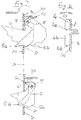
- Im einzelnen zeigen:
- Fig. 1
- die Vorderansicht auf eine Abfallpresse mit geöffneten Fronttüren,
- Fig. 2
- in vergrößertem Maßstab einen Schnitt gemäß der Linie A-A in Fig. 1 und
- Fig. 3
- im selben Maßstab einen Schnitt gemäß der Linie B-B in Fig. 1.
- Der grundsätzliche Aufbau und die Funktion einer Abfallpresse der in Fig. 1 dargestellten Art wird als bekannt vorausgesetzt; die Erläuterungen der einzelnen Zeichnungspositionen sind im Bezugsziffernverzeichnis angegeben. Dies gilt auch für Bedetung und Funktion der vertikalen Abstandsleisten 4 im Einfüllbereich E.
- Das Neue und Besondere bei der dargestellten Presse liegt nun in der generellen Kombination folgender Einzelmerkmale:
- a) Ortsfeste Abstandsleisten 4 an Rückwand R und/oder Innenseite 2a der Fronttür 2 im Einfüllbereich E des Schachtes S der Presse 1.
- b) Schwenkbar in Durchbrüchen D von Rückwand R sowie Fronttür 3 des Preßbereiches P im Schacht S angeordnete Rückhaltekrallen 5 und 6 für das bereits im unteren Schacht- bereich P zusammengepreßte Material bzw. den fertigen, noch nicht abgebundenen Ballen.
- In spezieller baulicher sowie anordnungsgemäßer Ausgestaltung weisen bei dieser Merkmalskombination die einzelnen Bauteile noch folgende wesentlichen Charakteristika auf:
- c) Die Abstandsleisten 4 sind mit horizontalem seitlichen Abstand c und c₁ zueinander angeordnet und ihre freien Enden 4a sind weitestgehend stumpfwinklig ausgebildet (Fig. 3).
- d) Die Abstandsleisten 4 erstrecken sich über die gesamte Höhe der Fronttür 2 des Einfüllbereichs E und setzen sich in kurzen separaten Ansatzstücken 4b im oberen Bereich der Preßschachttür 3 fort.
- Unterschiedliche Seitenabstände c und c₁ der Abstandsleisten 4 zueinander auf Schachtrückwand R und Fronttürinnenseite 2a sind konstruktionsbedingt erforderlich im Hinblick auf die noch näher beschriebene Anordnung und Ausbildung der Rückhaltekrallen 5 und 6.
- Zu letzteren ist dabei folgendes wichtig:
- e) Die Rückhaltekrallen 5 und 6 sind frei in den Preßbereich P hineinpendelnd über horizontale Schwenkbolzen in den Durchbrüchen D aufgehängt (Fig. 2) und ragen in unbelastetem Zustand nur mit ihren Nasen 5a bzw. 6a in den Schacht S hinein.
- f) Die Rückhaltekrallen 5 und 6 sind an Fronttür 3 und Schachtrückwand R mit unterschiedlich seitlichen d und d₁ sowie vertikalen Abständen a bzw. a₁ zueinander und zu den Abstandsleisten 4 seitlich versetzt b bzw. b₁ angeordnet.
- Weiterhin von funktioneller Wichtigkeit ist, daß die Rückhaltekrallen 5 und 6 eine unterschiedliche Grundform mit einer gestuften bzw. gezahnten Unterseite 5b bzw. 6b aufweisen und daß sie jeweils zumindest paarweise nebeneinander 5, 5 ... und parallel untereinander 5, 6 angeordnet sind und ihre obere Reihe 5, 5 ... oberhalb der tiefsten Stellung des Preßstempels K liegt.
- Dadurch, daß die obere Krallenreihe 5, 5 ... zudem die größeren Abmessungen aufweist, schwenken diese infolge des rückfedernden Materials weiter in den Preßschacht P hinein als die unteren 6, 6 - siehe hier die gestrichelten Darstellungen 5' und 6' in Fig. 2 - und geben der Ballenoberseite den nötigen Halt; Begrenzungsanschläge 5c und 6c markieren dabei die jeweiligen Endstellungen der freien Bewegbarkeit der Krallen 5 und 6. Damit letztlich der jeweilige Preßstempel K so nahe wie möglich an die Schachtwandungen heranreichen kann, ist die Stempelplatte in nicht dargestellter Weise noch mit zu den Leisten 4 und Krallen 5, 6 korrespondierenden Aussparungen versehen.
-
- 1
- Presse
- 2
- Fronttür (Einfüllbereich)
- 2a
- Innenseite
- 3
- Fronttür (Preßbereich)
- 3a
- Innenseite
- 3b
- Querstrebe, Anschlagleiste
- 4
- Abstandsleiste
- 4a
- freies Ende
- 4b
- Ansatz
- 5
- obere Rückhaltekralle
- 5a
- Nase
- 5b
- Unterseite
- 5c
- Begrenzungsanschlag
- 6
- untere Rückhaltekralle
- 6a
- Nase
- 6b
- Unterseite
- 6c
- Begrenzungsanschlag
- 7
- Schwenkbolzen
- B
- Bodenfläche
- D
- Durchbruch
- E
- Einfüllbereich
- K
- Preßstempel
- P
- Preßbereich
- R
- Schachtrückwand
- S
- Schacht der Presse
Claims (6)
- Abfallpresse, vornehmlich stehender Bauart und weitestgehend rechteckiger, in Preß- und Einfüllbereich unterteilter sowie mittels separater Fronttüren abgeriegelter Schachtbauweise, mit vertikal darin maschinell bewegtem Preßstempel samt Abstandsleisten und Rückhaltekrallen für das zu verpressende Material an den Schachtwandungen,
gekennzeichnet
durch die Kombination folgender Merkmale:a) Ortsfeste Abstandsleisten (4) an Rückwand (R) und/oder Innenseite (2a) der Fronttür (2) im Einfüllbereich (E) des Schachtes (S) der Presse (1).b) Schwenkbar in Durchbrüchen (E) von Rückwand (R) sowie Fronttür (3) des Preßbereichs (P) im Schacht (S) angeordnete Rückhaltekrallen (5 und 6) für das bereits im unteren Schachtbereich (P) zusammengepreßte Material bzw. den fertigen, noch nicht abgebundenen Ballen. - Abfallpresse nach Anspruch 1,
gekennzeichnet
durch folgende Merkmale der Abstandsleisten (4):c) Die Abstandsleisten (4) sind mit horizontalem seitlichen Abstand (c und c₁) zueinander angeordnet und ihre freien Enden (4a) sind weitestgehend stumpfwinklig ausgebildet (Fig. 3).d) Die Abstandsleisten (4) erstrecken sich über die gesamte Höhe der Fronttür (2) des Einfüllbereichs (E) und setzen sich in kurzen separaten Ansatzstücken (4b) im oberen Bereich der Preßschachttür (3) fort. - Abfallpresse nach den Ansprüchen 1 und 2,
gekennnzeichnet durch
unterschiedliche Seitenabstände (c und c₁) der Abstandsleisten (4) zueinander auf Schachtrückwand (R) und Fronttürinnenseite (2a). - Abfallpresse nach den Ansprüchen 1 bis 3,
gekennzeichnet
durch folgende Merkmale der Rückhaltekrallen (5 und 6):e) Die Rückhaltekrallen (5 und 6) sind frei in den Preßbereich (P) hineinpendelnd über horizontale Schwenkbolzen in den Durchbrüchen (D) aufgehängt (Fig. 2) und ragen in unbelastetem Zustand nur mit ihren Nasen (5a bzw. 6a) in den Schacht (S) hinein.f) Die Rückhaltekrallen (5 und 6) sind an Fronttür (3) und Schachtrückwand (R) mit unterschiedlich seitlichen (d und d₁) sowie vertikalen Abständen (a bzw. a₁) zueinander und zu den Abstandsleisten (4) seitlich versetzt (b bzw. b₁) angeordnet. - Abfallpresse nach Anspruch 4,
dadurch gekennzeichnet,
daß die Rückhaltekrallen (5 und 6) eine unterschiedliche Grundform mit einer gestuften bzw. gezahnten Unterseite (5b bzw. 6b) aufweisen. - Abfallpresse nach mindestens einem der vorhergehenden Ansprüche,
dadurch gekennzeichnet,
daß die Rückhaltekrallen (5 und 6) jeweils zumindest paarweise nebeneinander (5, 5 ...) und parallel untereinander (5, 6) angeordnet sind und ihre obere Reihe (5, 5 ...) oberhalb der tiefsten Stellung des Preßstempels (K) liegt.
Applications Claiming Priority (2)
| Application Number | Priority Date | Filing Date | Title |
|---|---|---|---|
| DE4445632 | 1994-12-21 | ||
| DE4445632A DE4445632C2 (de) | 1994-12-21 | 1994-12-21 | Abfallpresse |
Publications (3)
| Publication Number | Publication Date |
|---|---|
| EP0718093A2 true EP0718093A2 (de) | 1996-06-26 |
| EP0718093A3 EP0718093A3 (de) | 1997-01-29 |
| EP0718093B1 EP0718093B1 (de) | 2000-10-25 |
Family
ID=6536482
Family Applications (1)
| Application Number | Title | Priority Date | Filing Date |
|---|---|---|---|
| EP95117919A Expired - Lifetime EP0718093B1 (de) | 1994-12-21 | 1995-11-14 | Abfallpresse |
Country Status (5)
| Country | Link |
|---|---|
| US (1) | US5740726A (de) |
| EP (1) | EP0718093B1 (de) |
| JP (1) | JP3727988B2 (de) |
| AT (1) | ATE197135T1 (de) |
| DE (2) | DE4445632C2 (de) |
Cited By (1)
| Publication number | Priority date | Publication date | Assignee | Title |
|---|---|---|---|---|
| EP0782913A3 (de) * | 1996-01-02 | 1997-12-03 | Hermann Schwelling | Abfall-Ballenpresse |
Families Citing this family (6)
| Publication number | Priority date | Publication date | Assignee | Title |
|---|---|---|---|---|
| US5885049A (en) * | 1997-07-30 | 1999-03-23 | Mcneilus Truck And Manufacturing, Inc. | Ejection mechanism for refuse trucks |
| US20060219104A1 (en) * | 2005-04-01 | 2006-10-05 | Cnh America Llc | Cotton packager with interior wall including hold down elements for holding cotton in a compacted state |
| GB2459737B (en) * | 2008-05-07 | 2012-05-02 | Brian Murphy | Baling press for tyres |
| NL2006618C2 (nl) * | 2011-04-18 | 2012-10-22 | Keywaste B V | Persinrichting. |
| US11453188B2 (en) | 2018-04-30 | 2022-09-27 | Sebright Products, Inc. | Biased retainer assembly for waste container |
| JP7558525B2 (ja) * | 2020-08-31 | 2024-10-01 | Klass株式会社 | 圧縮減容梱包装置 |
Family Cites Families (24)
| Publication number | Priority date | Publication date | Assignee | Title |
|---|---|---|---|---|
| US532750A (en) * | 1895-01-22 | Cotton-press | ||
| US379414A (en) * | 1888-03-13 | Baling-press | ||
| GB1087152A (en) * | 1963-01-12 | 1967-10-11 | Walter Noel Powell | Improvements in and relating to baling presses |
| US3253537A (en) * | 1964-09-29 | 1966-05-31 | James I Porter | Trash compacting apparatus |
| US3765324A (en) * | 1971-06-14 | 1973-10-16 | Du Pont Canada | Apparatus for baling fibers |
| US3910181A (en) * | 1974-01-04 | 1975-10-07 | Fremco Manufacturing Inc | Baling press |
| US3903790A (en) * | 1974-10-16 | 1975-09-09 | Floyd R Gladwin | Trash compactor |
| US4002115A (en) * | 1975-02-06 | 1977-01-11 | Maurice Nanoia | Double baling press |
| US3996850A (en) * | 1975-07-31 | 1976-12-14 | Whitener Rufus A | Cotton gin press dogs |
| GB1565361A (en) * | 1976-01-29 | 1980-04-16 | Rolls Royce | Blade or vane for a gas turbine engien |
| US4118146A (en) * | 1976-08-11 | 1978-10-03 | United Technologies Corporation | Coolable wall |
| DE2658337C2 (de) * | 1976-12-23 | 1984-04-05 | Schwelling, Hermann, 7777 Salem | Presse für Abfallmaterialien |
| US4232599A (en) * | 1978-10-19 | 1980-11-11 | J. V. Manufacturing & Welding, Inc. | Waste paper compacter with front access features |
| US4182236A (en) * | 1978-11-30 | 1980-01-08 | Piqua Engineering, Inc. | Vertical baler with improved material hold-down and bale ejecting means |
| DE2911958C2 (de) * | 1979-03-27 | 1993-10-07 | Hoechst Ag | Verfahren zum Verpacken von faserigem Gut in Ballen sowie geeignete Preßanordnung dazu |
| DE2942239A1 (de) * | 1979-10-18 | 1981-04-30 | Feinwerktechnik Schleicher & Co, 7778 Markdorf | Steuerung des pressschild-antriebes und anderer pressenfunktionen bei ballenpressen |
| US4311092A (en) * | 1979-12-19 | 1982-01-19 | The American Baler Company | Low-profile vertical baling machine |
| DE3007903A1 (de) * | 1980-03-01 | 1981-11-12 | Hermann 7777 Salem Schwelling | Anzeige- und sicherheitsvorrichtung fuer abfallpessen |
| DE3734936A1 (de) * | 1987-10-15 | 1989-05-03 | Paals Packpressen Fabrik Gmbh | Ballenpresse |
| US5062358A (en) * | 1989-09-11 | 1991-11-05 | Marcella M. Fox | Bale ejector for a trash compactor |
| DE3942239A1 (de) * | 1989-12-21 | 1991-07-04 | Wacker Chemie Gmbh | Fuellstands-lotsystem |
| DE9204708U1 (de) * | 1991-06-14 | 1992-06-17 | Paal's Packpressen-Fabrik GmbH & Co KG, 4504 Georgsmarienhütte | Ballenpresse |
| EP0541207A1 (de) * | 1991-11-04 | 1993-05-12 | General Electric Company | Prallgekühltes Schaufelblatt mit einem die Blatthälften verbundendem Einsatz |
| DE4230775A1 (de) * | 1992-09-15 | 1994-03-17 | Paals Packpressen Fabrik Gmbh | Kanalballenpresse für Papier und sonstiges Abfallmaterial |
-
1994
- 1994-12-21 DE DE4445632A patent/DE4445632C2/de not_active Expired - Fee Related
-
1995
- 1995-11-14 AT AT95117919T patent/ATE197135T1/de not_active IP Right Cessation
- 1995-11-14 DE DE59508808T patent/DE59508808D1/de not_active Expired - Lifetime
- 1995-11-14 EP EP95117919A patent/EP0718093B1/de not_active Expired - Lifetime
- 1995-12-21 JP JP33359095A patent/JP3727988B2/ja not_active Expired - Fee Related
- 1995-12-21 US US08/576,805 patent/US5740726A/en not_active Expired - Fee Related
Non-Patent Citations (1)
| Title |
|---|
| None |
Cited By (1)
| Publication number | Priority date | Publication date | Assignee | Title |
|---|---|---|---|---|
| EP0782913A3 (de) * | 1996-01-02 | 1997-12-03 | Hermann Schwelling | Abfall-Ballenpresse |
Also Published As
| Publication number | Publication date |
|---|---|
| EP0718093A3 (de) | 1997-01-29 |
| DE4445632A1 (de) | 1996-06-27 |
| DE4445632C2 (de) | 1999-09-30 |
| DE59508808D1 (de) | 2000-11-30 |
| US5740726A (en) | 1998-04-21 |
| ATE197135T1 (de) | 2000-11-15 |
| EP0718093B1 (de) | 2000-10-25 |
| JPH08206885A (ja) | 1996-08-13 |
| JP3727988B2 (ja) | 2005-12-21 |
Similar Documents
| Publication | Publication Date | Title |
|---|---|---|
| CH673428A5 (de) | ||
| EP0718093B1 (de) | Abfallpresse | |
| DE2344698C2 (de) | Vorrichtung zum Verdichten von Müll | |
| DE1577221B2 (de) | Presse zum Verpressen von pulverförmigem Material | |
| AT519352B1 (de) | Pressen-Werkzeugunterbau | |
| DE2317632A1 (de) | Presse zum herstellen von ballen aus altmaterial | |
| DE2521570C3 (de) | Paketierpresse | |
| DE2035053C3 (de) | Presse zur Herstellung von Fonnteilen | |
| DE1289506B (de) | ||
| DE19808418A1 (de) | Antriebsvorrichtung für die Preßplatte von Abfall-Ballenpressen | |
| DE3624761C2 (de) | ||
| DE3527594C2 (de) | ||
| DE3319806C2 (de) | ||
| DE3842914A1 (de) | Presse | |
| DE19534807C2 (de) | Rahmenpresse | |
| DE2927298A1 (de) | Form zum formen von hohlsteinen | |
| DE8025174U1 (de) | Fuehrungsvorrichtung fuer den stoessel von abfallpressen liegender bauart | |
| DE29812091U1 (de) | Vorrichtung zum Spalten von Holz | |
| DE19831152A1 (de) | Form zur maschinellen Herstellung von Betonsteinen | |
| DE1583071C (de) | Strebausbauaggregat | |
| DE2530373A1 (de) | Schmiedepresse | |
| DE6610213U (de) | Form zur herstellung von baukoerpern, insbesondere platten aus beton oder aehnlichem material. | |
| DE2519027C2 (de) | Schreitende Ausbaueinheit, insbesondere Ausbaugespann | |
| DE1277117B (de) | Vorrichtung zum Verladen und Verdichten von Abfall od. dgl. | |
| DE836583C (de) | Selbstverkaeufer mit einer Reihe nebeneinander angeordneter Schubladen als Ausgabevorrichtungen |
Legal Events
| Date | Code | Title | Description |
|---|---|---|---|
| PUAI | Public reference made under article 153(3) epc to a published international application that has entered the european phase |
Free format text: ORIGINAL CODE: 0009012 |
|
| AK | Designated contracting states |
Kind code of ref document: A2 Designated state(s): AT DE DK ES FR GB SE |
|
| PUAL | Search report despatched |
Free format text: ORIGINAL CODE: 0009013 |
|
| AK | Designated contracting states |
Kind code of ref document: A3 Designated state(s): AT DE DK ES FR GB SE |
|
| 17P | Request for examination filed |
Effective date: 19970403 |
|
| GRAG | Despatch of communication of intention to grant |
Free format text: ORIGINAL CODE: EPIDOS AGRA |
|
| 17Q | First examination report despatched |
Effective date: 19991122 |
|
| GRAG | Despatch of communication of intention to grant |
Free format text: ORIGINAL CODE: EPIDOS AGRA |
|
| GRAG | Despatch of communication of intention to grant |
Free format text: ORIGINAL CODE: EPIDOS AGRA |
|
| GRAG | Despatch of communication of intention to grant |
Free format text: ORIGINAL CODE: EPIDOS AGRA |
|
| GRAH | Despatch of communication of intention to grant a patent |
Free format text: ORIGINAL CODE: EPIDOS IGRA |
|
| GRAH | Despatch of communication of intention to grant a patent |
Free format text: ORIGINAL CODE: EPIDOS IGRA |
|
| GRAA | (expected) grant |
Free format text: ORIGINAL CODE: 0009210 |
|
| AK | Designated contracting states |
Kind code of ref document: B1 Designated state(s): AT DE DK ES FR GB SE |
|
| PG25 | Lapsed in a contracting state [announced via postgrant information from national office to epo] |
Ref country code: ES Free format text: THE PATENT HAS BEEN ANNULLED BY A DECISION OF A NATIONAL AUTHORITY Effective date: 20001025 |
|
| REF | Corresponds to: |
Ref document number: 197135 Country of ref document: AT Date of ref document: 20001115 Kind code of ref document: T |
|
| PG25 | Lapsed in a contracting state [announced via postgrant information from national office to epo] |
Ref country code: AT Free format text: LAPSE BECAUSE OF NON-PAYMENT OF DUE FEES Effective date: 20001114 |
|
| REF | Corresponds to: |
Ref document number: 59508808 Country of ref document: DE Date of ref document: 20001130 |
|
| PG25 | Lapsed in a contracting state [announced via postgrant information from national office to epo] |
Ref country code: DK Free format text: LAPSE BECAUSE OF FAILURE TO SUBMIT A TRANSLATION OF THE DESCRIPTION OR TO PAY THE FEE WITHIN THE PRESCRIBED TIME-LIMIT Effective date: 20010125 |
|
| GBT | Gb: translation of ep patent filed (gb section 77(6)(a)/1977) |
Effective date: 20010108 |
|
| PLBE | No opposition filed within time limit |
Free format text: ORIGINAL CODE: 0009261 |
|
| STAA | Information on the status of an ep patent application or granted ep patent |
Free format text: STATUS: NO OPPOSITION FILED WITHIN TIME LIMIT |
|
| 26N | No opposition filed | ||
| REG | Reference to a national code |
Ref country code: GB Ref legal event code: IF02 |
|
| PGFP | Annual fee paid to national office [announced via postgrant information from national office to epo] |
Ref country code: FR Payment date: 20061030 Year of fee payment: 12 |
|
| PGFP | Annual fee paid to national office [announced via postgrant information from national office to epo] |
Ref country code: GB Payment date: 20061109 Year of fee payment: 12 |
|
| GBPC | Gb: european patent ceased through non-payment of renewal fee |
Effective date: 20071114 |
|
| REG | Reference to a national code |
Ref country code: FR Ref legal event code: ST Effective date: 20080930 |
|
| PG25 | Lapsed in a contracting state [announced via postgrant information from national office to epo] |
Ref country code: GB Free format text: LAPSE BECAUSE OF NON-PAYMENT OF DUE FEES Effective date: 20071114 |
|
| PG25 | Lapsed in a contracting state [announced via postgrant information from national office to epo] |
Ref country code: FR Free format text: LAPSE BECAUSE OF NON-PAYMENT OF DUE FEES Effective date: 20071130 |
|
| PGFP | Annual fee paid to national office [announced via postgrant information from national office to epo] |
Ref country code: DE Payment date: 20121113 Year of fee payment: 18 |
|
| PGFP | Annual fee paid to national office [announced via postgrant information from national office to epo] |
Ref country code: SE Payment date: 20121113 Year of fee payment: 18 |
|
| REG | Reference to a national code |
Ref country code: SE Ref legal event code: EUG |
|
| REG | Reference to a national code |
Ref country code: DE Ref legal event code: R119 Ref document number: 59508808 Country of ref document: DE Effective date: 20140603 |
|
| PG25 | Lapsed in a contracting state [announced via postgrant information from national office to epo] |
Ref country code: DE Free format text: LAPSE BECAUSE OF NON-PAYMENT OF DUE FEES Effective date: 20140603 Ref country code: SE Free format text: LAPSE BECAUSE OF NON-PAYMENT OF DUE FEES Effective date: 20131115 |