EP0718112A1 - Dispositif d'impression - Google Patents
Dispositif d'impression Download PDFInfo
- Publication number
- EP0718112A1 EP0718112A1 EP95114844A EP95114844A EP0718112A1 EP 0718112 A1 EP0718112 A1 EP 0718112A1 EP 95114844 A EP95114844 A EP 95114844A EP 95114844 A EP95114844 A EP 95114844A EP 0718112 A1 EP0718112 A1 EP 0718112A1
- Authority
- EP
- European Patent Office
- Prior art keywords
- printing unit
- unit according
- pawl
- shaft
- printing
- Prior art date
- Legal status (The legal status is an assumption and is not a legal conclusion. Google has not performed a legal analysis and makes no representation as to the accuracy of the status listed.)
- Granted
Links
- 230000000903 blocking effect Effects 0.000 claims abstract description 8
- 230000002093 peripheral effect Effects 0.000 claims abstract 4
- 230000005540 biological transmission Effects 0.000 claims description 10
- 238000011144 upstream manufacturing Methods 0.000 claims description 9
- 230000001133 acceleration Effects 0.000 claims description 6
- 229910000831 Steel Inorganic materials 0.000 claims description 2
- 239000002184 metal Substances 0.000 claims description 2
- 239000004033 plastic Substances 0.000 claims description 2
- 239000010959 steel Substances 0.000 claims description 2
- 230000007246 mechanism Effects 0.000 abstract 2
- 230000001419 dependent effect Effects 0.000 abstract 1
- 238000013461 design Methods 0.000 description 5
- 238000001514 detection method Methods 0.000 description 2
- 238000003780 insertion Methods 0.000 description 2
- 230000037431 insertion Effects 0.000 description 2
- 238000000034 method Methods 0.000 description 2
- 239000004809 Teflon Substances 0.000 description 1
- 229920006362 Teflon® Polymers 0.000 description 1
- 230000003213 activating effect Effects 0.000 description 1
- 230000006978 adaptation Effects 0.000 description 1
- 238000004140 cleaning Methods 0.000 description 1
- 238000004040 coloring Methods 0.000 description 1
- 210000001520 comb Anatomy 0.000 description 1
- 230000006835 compression Effects 0.000 description 1
- 238000007906 compression Methods 0.000 description 1
- 238000010276 construction Methods 0.000 description 1
- 238000011109 contamination Methods 0.000 description 1
- 230000003993 interaction Effects 0.000 description 1
- 230000036316 preload Effects 0.000 description 1
- 230000002040 relaxant effect Effects 0.000 description 1
- 230000035939 shock Effects 0.000 description 1
- 238000005476 soldering Methods 0.000 description 1
- 238000012546 transfer Methods 0.000 description 1
- 238000013519 translation Methods 0.000 description 1
Images



Classifications
-
- B—PERFORMING OPERATIONS; TRANSPORTING
- B41—PRINTING; LINING MACHINES; TYPEWRITERS; STAMPS
- B41K—STAMPS; STAMPING OR NUMBERING APPARATUS OR DEVICES
- B41K3/00—Apparatus for stamping articles having integral means for supporting the articles to be stamped
- B41K3/02—Apparatus for stamping articles having integral means for supporting the articles to be stamped with stamping surface located above article-supporting surface
- B41K3/12—Apparatus for stamping articles having integral means for supporting the articles to be stamped with stamping surface located above article-supporting surface with curved stamping surface for stamping by rolling contact
- B41K3/121—Apparatus for stamping articles having integral means for supporting the articles to be stamped with stamping surface located above article-supporting surface with curved stamping surface for stamping by rolling contact using stamping rollers having changeable characters
- B41K3/123—Apparatus for stamping articles having integral means for supporting the articles to be stamped with stamping surface located above article-supporting surface with curved stamping surface for stamping by rolling contact using stamping rollers having changeable characters having adjustable type-carrying wheels
Definitions
- the invention relates to a printing unit with the features in the preamble of claim 1.
- a printing unit of this type is known (DE 30 47 390 C2), which has a relatively complicated and complex drive device, slip clutch and sensing device.
- the invention has for its object to provide a printing unit of the type mentioned, which has a simple, space-saving and large drive torques and speeds enabling drive.
- Such a drive device enables high torques and speeds, the rest of the prerequisites being created for driving a plurality of printing units of a printing device which are successively arranged and rotating in the circumferential direction by means of the stationary disk of the drive device.
- the drive device does not require a special motor.
- the drive device is of mechanical construction simple and significantly reduces the parts required for the drive. It is also advantageous that this creates the conditions for a compact, compact design for each printing unit, so that printing devices, for example printing cylinders, up to 120 printing units can be formed, the individual type wheels of each printing unit being controllable individually and as desired are and all type wheels can be monitored, so that the advantage of a fully automatically adjustable printing unit can also be fully realized or maintained.
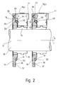
- 1 and 2 show part of a printing device 10 which has a large number of individual, identically designed printing units 11.
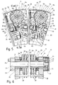
- 1 shows eight printing units 11a, 11b, 11c, 11d, 11e, 11f, 11g and 11h arranged in the circumferential direction at intervals from each other on a support 12, these printing units all rotating together in the direction of arrow 13 and an all common stationary disk 14 is assigned to this as a drive.
- 8 printing units 11 shown a larger number of these can also be provided in the circumferential direction, e.g. 12 printing units or up to 20 printing units.
- the carrier 12 of this in the circumferential direction within a common radial plane printing units 11a to 11h consists e.g. from a drum 15, which is only indicated schematically. This carrier 12 and with it the printing units 11a to 11h are arranged on a shaft 16 common to all and are driven by means of the latter in the direction of the arrow 13, relative to the stationary disk 14.
- a plurality of identically designed printing units are arranged one behind the other, which are designated in Fig. 2 with 11g1 and 11g2, each printing unit 11g1 and 11g2 on this imagined Axle line as a drive is assigned a disc 14 or 18. If one follows the circumferential course of the disk 14, Thus, for example, the 8 printing units 11a to 11h (FIG. 1) are arranged along this. If one follows the circumferential course of the next disk 18 arranged at an axial distance on the shaft 16, 8 or more printing units of the same type as the printing group 11g2 are also arranged along this circumferential course. Viewed in the direction of the axis of rotation 17, many individual, identical printing units 11 can be arranged at axial distances from one another, for example 10 such printing units 11g1, 11g2 and the following.
- Each printing unit 11 has a plurality of identically designed type wheels 19 which are rotatably arranged next to one another on a common shaft 20 and can be driven by this via a respective slip clutch 21 in the form of a friction disk 22.
- types 23 are arranged in the form of numbers, letters, characters or the like, which are expediently placed as shown, as shown. This is highlighted in particular in FIG. 4.
- each type wheel 19 has a total of twelve types 23 on its circumference at equal circumferential angular distances from one another, ten types 23 being formed as numbers from zero to nine, one type 23 being formed as a letter and the twelfth type 23 being formed by an empty field is that enables the setting "non-printing".
- the letter type and the blank field are arranged between the number types 1 and 0.
- the respective friction disc 22 is positively coupled to the shaft 20. This is done by means of a radial driver 24, for example a nose, of the friction disk 22, which engages in a form-fitting manner in a groove 25 of the shaft 20.
- Each friction disc 22 is made of plastic, for example Teflon, coated metal, in particular steel, which ensures great stability and a constant friction torque is guaranteed.
- the friction disks 22 are pressed against the respective type wheel 19 via axial pressure.
- the wheel set consisting of the type wheels 19 and the friction disks 22 placed therebetween, shown as a unit in FIG. 3, is placed on the shaft 20.
- the axial pressure which compresses the wheelset, is achieved by spring washers 26 and 27 on both sides, which are placed between respective washers, the outer of which can be, for example, a retaining ring which is held in an annular groove in the shaft 20.
- the wheel set is preloaded by the spring washers 26, 27. It can be closed off by means of caps 28 if necessary.
- the type wheels 19 are rotated almost synchronously by the friction generated in this way when the shaft 20 rotates.
- Each type wheel 19 is assigned a sensing device 29 which fixes its position and a pawl 30 for engagement in the type wheel 19. Details of the pawl 30 and the locking function thereof will be explained in more detail later.
- Each pawl 30 is assigned an actuator 31 which can be controlled as a function of the sensing device 29 via a control device (not shown further).
- this actuator 31 consists in each case of an electromagnet which, in a special design, serves as a holding magnet.
- the actuator 31 instead consists of a piezo actuator 131, where the pawl 130 is configured differently than in the first embodiment. Otherwise, however, the second exemplary embodiment in FIG. 10 corresponds to the first exemplary embodiment according to FIGS. 1 to 9.
- Each pawl 30 per type wheel 19 is by means of its associated actuator 31, for example holding magnets, between a blocking position blocking the type wheel 19, as shown in FIG 5 is shown on the right, and a release position releasing the type wheel 19 is controllable, as is shown, for example, in FIG. 5 on the left.
- a drive device for temporarily driving the shaft 20 and thus the wheel set is provided thereon, this drive not occurring continuously but only for a specific setting time in which the printing unit 11 is set fully automatically.
- the drive device also includes a drive shaft 32, which is coupled to the shaft 20 of each printing unit 11 and carries a drive gear 33 at one end.
- the respective drive gear 33 per printing unit 11a to 11h is assigned an externally toothed toothed segment 34 in the area of the disk 14 on the pitch circle of the drive gear 33, with which the respective drive gear 33 can be brought into engagement when the printing unit 11a to 11h rotates.
- the toothed segment 34 extends over a circumferential angle, for example less than 160 °, for example in the range from 80 ° to 110 °. Only for the time during which the drive gear 33 is in engagement with the toothed segment 34 is the drive of the printing unit 11 rotating. This time is available as a setting time for the individual type wheels 19 of each wheel set.
- the drive gear 33 carries an eccentric projection 35, which e.g. has a role not shown here.
- the disk 14, 18 has a path 36, for example upstream of the beginning of the tooth segment 34 in the circumferential direction according to arrow 13 and interacting with the eccentric projection 35, e.g. in the form of a groove 37, which is designed as a cam track and generates a drive of the drive shaft 32 upstream of the engagement of the drive gear 33 in the toothed segment 34 in the same direction of rotation, preferably an acceleration. In addition, this ensures a defined tooth engagement of the drive gear 33 in the toothed segment 34.
- the eccentric projection 35 and the track 36, in particular groove 37 achieve a soft acceleration of the drive shaft 32 and thus of the entire wheel set driven above it. This acceleration when driving the wheelset eliminates, or at least considerably reduces, impacts, shocks and the like, abrupt loads at the beginning of the toothing engagement, which lead to damage and excessive wear. A soft, shock-free start of the drive is achieved.
- the path 36 extends over a circumferential angle which is, for example, greater than 200 ° and in particular, for example, is in the range from 250 ° to 280 °.
- This circumferential angle of the web 36 is matched to that of the toothed segment 34.
- the path 36, for example groove 37 adjoins this at both ends of the toothed segment 34, an end section 38 extending radially outward being provided in the region of the path 36, for example groove 37, upstream of the beginning of the toothed segment 34.
- the path 36 for example the groove 37, runs essentially on the pitch circle of the drive gear 33 or the toothed segment 34, the end section 38 extending outward at the end of the path 36. This end section 38 causes the explained acceleration of the drive shaft 32 and thus represents an acceleration section.
- a radial starting section 39 is provided, which merges radially from the inside into the web 36, at least slightly, and thus ensures that the projection 35 runs well into the web 36 when the drive gear 33 at the end of the toothed segment 34 disengaged from this.
- the web 36, in particular groove 37 contains an inlet slot 40 which is open radially outwards for the insertion of the eccentric projection 35 into the groove 37.
- the drive of the wheel set, in particular the shaft 20, takes place from the drive shaft 32 via a transmission gear 41 which, for example, causes a translation into slow speed.
- the transmission gear 41 consists in particular of a planetary gear.
- the drive shaft 32 is coupled to the shaft 20 to be driven via the transmission gear 41.
- the shaft 20 is designed as a hollow shaft. As a result, the drive shaft 32 can run coaxially with the hollow shaft 20. This saves space.
- the transmission gear 41 in particular planetary gear, is arranged on one end of the drive shaft 32 and on the one opposite the end carrying the drive gear 33.
- the planetary gear has a ring gear 42 held on the printing unit 11, for example its housing 9, in a rotationally fixed manner and, as a sun gear, a drive pinion 43 non-rotatably connected to the drive shaft 32, with which the planet gears 44 are engaged, which in turn are rotatably mounted on the shaft 20, for example by means of indicated bearing bolts 45.
- the transmission gear 41 and the drive for the shaft 20 as a whole can be designed such that it is rotated by more than 360 ° C circumferential angle so that the highest possible machine speeds can be achieved.
- the shaft 20 and the drive shaft 32 can be supported by means of plain bearings.
- the housing 9 can be divided be, whereby a disassembly of the complete wheel set in the axial direction is possible in a simple manner.
- the arrangement can be chosen so that the drive shaft 32 can be pulled out of the transmission gear 41 in Fig. 6 to the left. This is achieved in that the drive pinion 43 has a smaller diameter than the drive shaft 32.
- the transmission gear 41 can remain connected to the right wall of the housing 9 in FIG. 6 even after the wheel set has been removed.
- the circumferential angular extent of the toothed segment 34 is dimensioned such that the type wheels 19 of each printing unit 11 are only driven for a predetermined setting time, the shaft 20 being rotated by more than 360 °, as already explained.
- each pawl 30 can be held in its release position (FIG. 5, left) and out of engagement with the type wheel 19 by means of the respective actuator 31.
- the respectively assigned actuator 31, in particular the electromagnet can be activated, in particular switched on, so that the pawl 30 is held in this release position by means of the actuator 31.
- the actuator 31 can also be controlled into a position releasing the pawl 30, in which case the released pawl can be pushed into its blocking position by the force of a spring 46 acting on it, which is shown on the right in FIG. 5.
- the actuators 31, in particular electromagnets are only used as holding magnets.
- the respective spring 46 is received in a receptacle 47 of the housing 9 and is supported on the pawl 30 with its end located at the bottom in FIG. 5.
- the preload of the Spring 46 can be adjustable.
- the spring 46 is designed as a compression spring. Because the respective actuator 31, in particular the electromagnet, only serves as a holding magnet and each pawl 30 can be pushed into its locking position (FIG. 5, right) by means of the spring 46, each type wheel 19 is blocked by the pawl 30 in the de-energized state.
- the design makes it possible to use strong springs 46. This allows large forces to be applied to transfer each pawl 30 into the locked position.
- the actuator 31, in particular an electromagnet, enables a large magnetic holding force.
- the release position of the pawl 30 is guaranteed not only with a small air gap but also with a larger air gap in the area of the electromagnet. It is possible, when activating the actuator 31, in particular the electromagnet, to pull the respective pawl 30 fully against the stop.
- All pawls 30 of each individual printing unit 11 are pivotally mounted on a common axis 48.
- a lifting device 49 common to all the pawls 30 of the respective printing unit 11, by means of which all the pawls 30 can be lifted off together and brought into an initial position in the time that is outside the setting time of the type wheels 19.
- the lifting device 49 has an eccentric projection 50 for each printing unit 11 at the end of a lifting shaft common to all pawls 30 and not shown further.
- the stationary disk 14 has an approximately circular cam track 51, for example groove 52, which is assigned to a plurality of circumferential printing units 11a to 11h which are arranged in succession in the circumferential direction, and with which the projection 50 constantly rotates during rotation Intervention stands.
- the next following disc 18 (FIG. 2) at a distance from the disc 14 is provided with a corresponding cam track 51, in particular groove 52.
- This cam track 51 in particular groove 52, has an arc section 53 deviating from the circular shape on the circumferential area, which precedes the start of the setting time of the type wheels 19.
- the arc section 53 together with the eccentric projection 50, controls a lifting movement for the pawls 30 of the respective printing unit 11.
- the eccentric projection 50 consists e.g. from a roll.
- the cam track 51, in particular groove 52 has an inlet 54 which is open radially outwards for the insertion of the projection 50, in particular the roller, into the cam track 51.
- Both the type wheels 19 and the lifting device 49 for the pawls 30 are thus driven with the aid of the stationary, two-lane disc 14 with toothed segment 34, namely for all printing units 11a to 11h placed at a distance from one another in the circumferential direction within a common radial plane.
- Such a drive device is not only simple and inexpensive but also space-saving and has the particular advantage that no drive motor is necessary and large torques and speeds can be achieved, a drive of z. B. up to 20 printing units 11a to 11h is possible with these advantages.
- the fact that high torques and high speeds can be achieved results in greater safety because it is possible to work with larger forces. These greater forces are thus applied in a simple and space-saving manner by this drive device. High speeds of up to 10,000 rpm can be achieved.
- Each pawl 30 has a locking tooth 55 for engaging in a radial distance from the bearing on the axis 48 identical tooth gap 56 between two successive teeth 57 of a locking device 58 of the respective type wheel 19, for example a locking disk 59 fixed therewith, each locking tooth 55 being designed for blocking in both directions of rotation of the type wheel 19. There is therefore almost no play between a tooth gap 56 and the locking tooth 55 of the pawl 30 engaging therein. The respective type wheel 19 is thus locked in both directions of rotation. Any bouncing back of the type wheel 19 when stopping is thus also prevented.
- the teeth 57 of the locking device 58 are approximately designed in a side view corresponding to the teeth of a circular saw blade, which can best be seen from FIG. 4.
- the tooth gaps 56 are approximately U-shaped, the center line of the U, however, not running in the direction of a radial, but in the direction of a secant, based on the central axis of each type wheel 19 and each locking disk 59.
- Another special feature is that the respective , in the circumferential direction of the tooth gap 56 upstream tooth 57 has a tooth back 60 sloping towards the tooth gap 56.
- the ratchet tooth 55 of each pawl 30 has a section engaging in the U-shaped tooth gap 56 and on one side an inclined edge 61 starting from the foot of this section, which can come to rest on the inclined tooth back 60, as shown in FIG. 5, right Picture shows.
- the locking device 58 in particular locking disk 59, is an integral part of the type wheel 19, e.g. with this either in one piece or as a separate disk firmly connected to the type wheel 19, e.g. by soldering.
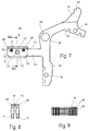
- Each pawl 30 is a flat, one-piece structure. It has a total of three strutting arms 62, 63 and 64 running at a radial distance from the axis 48.
- the arms 62 and 63 are oriented approximately at right angles to one another, arm 63 extends approximately at right angles from a substantially rectilinear leg which carries arm 62 in extension.
- the third arm 64 extends on the right side of the arm 62 in FIG. 7 and above the bearing bore 68 with which the pawl 30 is rotatably mounted on the axis 48.
- the third arm 64 extends at an angle of less than 90 ° to the first arm 62.
- Each arm 62, 63 and 64 is equally designed to hold an associated armature 65 or 66 or 67, which together with the actuator 31, in particular electromagnets, serves to control the pawl 30.
- Each arm 62 to 64 with armature 65 to 67 thereon is assigned an actuator 31 or 69 or 70, in particular an electromagnet, which is grouped around the axis 48 and follows one another at intervals in the direction of the axis 48. This results in a particularly compact design which further reduces the axial dimension of each printing unit 11.
- a first pawl 30 is provided, which carries on its first arm 62 a first armature 65, to which a first actuator 31 is assigned for actuation.
- a second pawl which carries an armature 66 on its second arm 63, this second arm 63 with armature 66 being assigned a second actuator 69, in particular an electromagnet.
- a third pawl 30 which carries a third armature 67 on its third arm 64, to which a third actuator 70, in particular an electromagnet, is assigned.
- first pawl 30 which carries on its first arm 62 a first armature 65 to which a first actuator 31, in particular an electromagnet, is assigned.
- second pawl 30 which carries a second armature 66 on its second arm 63, to which a second actuator 69, in particular an electromagnet, is assigned.
- This order continues then viewed along axis 48.
- each pawl 30 the receptacle and holder provided on the first arm 62 or second arm 63 or third arm 64 for the first armature 65 or second armature 66 or third armature 67 are each designed identically. Details in this regard are explained with reference to FIGS. 7 to 9 using the example of the second arm 63 and a second armature 66 attached to it.
- the respective armature 66 is held on the respective arm 63 of the pawl 30 in a resilient, at least cushioned manner.
- Each anchor 66 has an approximately U-shape, the two U-legs 71, 72 laterally engaging over the respective arm 63 of the pawl 30, in each case on the outside.
- Each arm 62-64 includes passages 76, 77 and 78, e.g. a bore which is passed through for fastening the respective armature 65 or 66 or 67 by a retaining bolt 79 which penetrates the associated armature 66, in particular its two U-legs 71, 72, with radial play, so that against the action of the Springs 74 a deflection of the armature 66 relative to the arm 63 is still possible.
- Each armature 65 to 67 has, as shown in FIGS. 7 to 9 for the second armature 66, surface depressions 80 and / or surface elevations 81 on its outer surface of its transverse web 73 facing the respective electromagnet, in particular e.g. Longitudinal grooves and / or transverse grooves. This prevents any sticking to the electromagnet, even if the surface of the cross piece 73 should be dirty.
- each type wheel 19 carries twelve types 23 for each printing unit 11, so is each type wheel 19 assigned locking device 58, in particular locking disk 59, is provided with twelve teeth 57 which follow one another at equal circumferential angular intervals.
- a sensing device 29 is assigned to each individual type wheel 19.
- Each sensing device 29 has three hall sensors 82, 83 and 84 arranged at intervals from one another along the orbit of the type wheel 19.
- the sensing device 29 includes a hybrid circuit, not shown, with a suitable chip. Electrical cables lead from the sensing device 29 to a central control device (not shown further here).
- individual permanent magnets 85 of different polarity which are placed along the circumference of each type wheel 19, are also part of the sensing device 29.
- the permanent magnets 85 are each arranged on the circumferential area between two types 23, but not every intermediate area between two types 23 has permanent magnets 85.
- the permanent magnets 85 can e.g. be grouped in the order S S O N S O S N O N N O, as is the case in FIG. 3.
- N north pole
- O no permanent magnet
- S south pole.
- the arrangement is such that each type 23 of a type wheel 19 is identified by the signals from two permanent magnets 85, i.e. when exactly two magnetic signals are present, e.g. once N and once S, clearly a Type 23 has been reached and the adjacent Type 23 is thus clearly identified. Only a magnetic signal means that Type 23 has not yet been reached. With the second magnetic signal, Type 23 is immediately clearly identified. There are no combinations of three.
- the described design of the sensing device 29 with three Hall sensors 82 to 84 for scanning directly on the respective Type wheel 19 has the advantage of quick and reliable detection and small dimensions. Since each type wheel 19 has a total of twelve parts, ie can carry twelve types 23, each with the coding shown above, ie arrangement of the permanent magnets 85, there is the advantage that all types 23 can be identified clearly and quickly by two magnetic signals. Ten types 23 are needed for the numbers zero to nine.
- the eleventh Type 23 is, for example, a cancellation stamp, letter or the like. possible so that when the respective type wheel 19 is set to this eleventh type 23 a cancellation stamp can be printed. Until now, separate, controlled cancellation machines in an additional printing station of the printing device 10 were necessary for the cancellation.
- the cancellation mark can be printed by means of the respective printing unit 11 by appropriate setting of the respective type wheel 19.
- An empty field can be provided as the twelfth Type 23.
- This enables a printing unit 11 to be easily switched off. All printing units 11 of the printing device 10 can thus be switched to print cutoff by appropriate setting of their respective type wheels 19, so that this function does not have to be present on the printing press or need not be controlled separately.
- the fully automatically adjustable printing unit 11 also has the advantage that any, even non-sequential, numbers can be set as desired. There is therefore no need for mechanically different plants for different applications.
- the setting can be made in a time of 100 ms, from printing to coloring. Even faster settings are possible. With everything, a reliable detection of the respective types 23 of each type wheel 19 is guaranteed. Another advantage is the very small size. As a result, printing devices, for example numbering cylinders, with up to 120 numbering units, each with twelve type wheels 19, can be provided, all type wheels 19 being optionally controllable and monitored. Print speeds of up to 18000 U / h are possible.
- Each printing unit 11 is driven during the available setting time, specifically when the drive gear 33 comes into engagement with the toothed segment 34 of the stationary disk 14 during rotation.
- a simultaneous lifting of all pawls 30 against the action of the respective spring 46 has been effected beforehand via the arc section 53 and the eccentric projection 50 of the lifting device 49.
- all actuators 31, 69, 70 and following have been activated by the control device and the individual pawls 30 have been brought into the release position, in which they are held electromagnetically by the interaction of the respective electromagnets with the armatures of the pawls.
- the individual type wheels 19 can be driven freely.
- the individual type wheels 19 are rotated via the driven drive shaft 32, the transmission gear 41 and the shaft 20 and the respective slip clutch 21, in particular friction disks 22.
- the individual type wheels 19 are stopped by switching off the power supply of each individual actuator 31, 69, 70 at a predetermined time and when the sensing device 29 has determined that the respectively desired, predetermined type 23 of the respective type wheel 19 has assumed the printing position. Then switching off the power supply of the respective actuator 31, 69, 70 results in the release of the pawl 30, which is then transferred by means of the relaxing spring 46 into its locked position (FIG. 5, right), in which there is a tooth gap 56 engaging locking tooth 55, the type wheel 19 is positively prevented from further rotation.
- the point in time for the switch-off current pulse is determined by the control device as a function of the types 23 to be set and when the specified type 23 is reached, which are coded by the permanent magnets 85 embedded in the type wheels 19 and are controlled by the Hall sensors 82, 83 and 84, Approved. Then the printing process takes place. After the impression and before the next adjustment process, all the pawls 30 are brought back into the mentioned starting position by the lifting device 49, in which they remain until the actuators 31, 69, 70 are switched on.
- the second exemplary embodiment shown in FIG. 10 also works in the same way.
- the shaft 20 is also rotated by more than 360 ° during the setting time via the drive shaft 32.
- the type wheels are prevented from rotating with the shaft 20 by pawls 130 which are urged into their locking position by means of the spring 46.
- the pawls 130 are brought into the release position in that the respective actuators 131 are activated in the form of piezo elements by applying a voltage. If the desired type 23 per type wheel 19 is reached in the automatic setting, the power supply to the actuator 131 is interrupted so that the respective spring 46 can move the pawl 130 into the locked position.
Landscapes
- Rotary Presses (AREA)
- Printers Or Recording Devices Using Electromagnetic And Radiation Means (AREA)
- Ink Jet (AREA)
- Inking, Control Or Cleaning Of Printing Machines (AREA)
- Transmission Devices (AREA)
Applications Claiming Priority (2)
| Application Number | Priority Date | Filing Date | Title |
|---|---|---|---|
| DE4446273 | 1994-12-23 | ||
| DE4446273A DE4446273A1 (de) | 1994-12-23 | 1994-12-23 | Druckwerk |
Publications (2)
| Publication Number | Publication Date |
|---|---|
| EP0718112A1 true EP0718112A1 (fr) | 1996-06-26 |
| EP0718112B1 EP0718112B1 (fr) | 1998-10-28 |
Family
ID=6536901
Family Applications (1)
| Application Number | Title | Priority Date | Filing Date |
|---|---|---|---|
| EP95114844A Expired - Lifetime EP0718112B1 (fr) | 1994-12-23 | 1995-09-21 | Dispositif d'impression |
Country Status (6)
| Country | Link |
|---|---|
| US (1) | US5660106A (fr) |
| EP (1) | EP0718112B1 (fr) |
| JP (1) | JP3803983B2 (fr) |
| AT (1) | ATE172674T1 (fr) |
| DE (3) | DE4446273A1 (fr) |
| ES (1) | ES2124948T3 (fr) |
Cited By (15)
| Publication number | Priority date | Publication date | Assignee | Title |
|---|---|---|---|---|
| EP0850775A1 (fr) * | 1996-12-24 | 1998-07-01 | Kazunosuke Makino | Roue porte-caractères et procédé de fabrication associé |
| EP1728628A1 (fr) | 2005-06-01 | 2006-12-06 | Kba-Giori S.A. | Machine d'impression typographique à entraînements indépendants |
| EP1889719A1 (fr) | 2006-08-16 | 2008-02-20 | Kba-Giori S.A. | Montage de dispositif de numérotation sur un cylindre de numérotation |
| WO2008052514A1 (fr) * | 2006-11-02 | 2008-05-08 | Atlantic Zeiser Gmbh | Unité d'impression |
| US7975906B2 (en) | 2005-06-08 | 2011-07-12 | Kba-Giori S.A. | Numbering process for securities, method for processing the numbered securities and numbering device to carry out the numbering process |
| US8225714B2 (en) | 2006-08-16 | 2012-07-24 | Kba-Giori S.A. | Mounting of numbering devices onto numbering cylinders |
| US8387496B2 (en) | 2007-04-13 | 2013-03-05 | Kba-Notasys Sa | Method and system for producing notes of securities |
| EP2772355A1 (fr) | 2013-02-28 | 2014-09-03 | KBA-NotaSys SA | Procédé de numérotation de feuilles et machine de traitement de feuilles pour la mise en oeuvre de ce procédé |
| CN105730034A (zh) * | 2014-12-08 | 2016-07-06 | 余敏守 | 金属工件标示打印装置 |
| CN110315892A (zh) * | 2019-06-17 | 2019-10-11 | 浙江易正智能科技有限公司 | 转盘式自动车牌制作机 |
| DE202021104907U1 (de) | 2020-09-10 | 2021-09-20 | Zeiser Gmbh | Nummerierwerk mit universellem Unterteil für vertikale und horizontale Nummerierwerke |
| DE202021104906U1 (de) | 2020-09-10 | 2021-09-20 | Zeiser Gmbh | Klemm-Fixierung von Nummerierwerken |
| DE202021104908U1 (de) | 2020-09-10 | 2021-09-20 | Zeiser Gmbh | Nummerierwerk mit variabler Typenradbreite |
| DE202024106234U1 (de) | 2023-10-30 | 2025-02-05 | Zeiser Gmbh | Vorrichtung zum Einstellen von Nummerierwerken auf einen konkreten Wert einer durch ein Nummerierwerk aufzudruckenden Zeichenfolge |
| WO2025082570A1 (fr) | 2023-10-17 | 2025-04-24 | Zeiser Gmbh | Procédé d'impression d'un document de sécurité comportant une chaîne de caractères déviant d'une orientation linéaire, machine de numérotation associée et document de sécurité |
Families Citing this family (15)
| Publication number | Priority date | Publication date | Assignee | Title |
|---|---|---|---|---|
| EP1389524A1 (fr) * | 2002-08-16 | 2004-02-18 | Kba-Giori S.A. | Méthode et dispositif pour numéroter |
| EP1607234A1 (fr) | 2004-06-17 | 2005-12-21 | Kba-Giori S.A. | Procédé et appareil pour créer des marques sur des papiers de sécurité |
| EP2032364B2 (fr) | 2006-06-23 | 2020-08-12 | KBA-NotaSys SA | Dispositif de numérotation pour la numérotation typographique |
| AU2013209307B2 (en) * | 2006-06-23 | 2015-02-19 | Kba-Notasys Sa | A numbering device for typographic numbering |
| EP1892099A1 (fr) | 2006-08-22 | 2008-02-27 | Kba-Giori S.A. | Méthode pour contrôler la position des roues d'impression d'une machine à numéroter |
| DE102011008859B3 (de) * | 2011-01-18 | 2012-06-06 | Paul Leibinger Gmbh & Co. Kg | Nummerierwerk |
| DE102011100847B4 (de) | 2011-05-06 | 2013-04-18 | Atlantic Zeiser Gmbh | Druckwerk |
| CN102320195B (zh) * | 2011-07-14 | 2013-08-14 | 北京印钞有限公司 | 一种号码机 |
| JP6142123B2 (ja) * | 2015-03-20 | 2017-06-07 | 株式会社東邦プリンテック | 番号印刷装置および活字輪 |
| DE102015212059B4 (de) | 2015-06-29 | 2022-10-20 | Zeiser Gmbh | Nummerierdruckwerk zum Bedrucken eines Sicherheitsdokuments und Sicherheitsdokument |
| FR3041834B1 (fr) * | 2015-09-25 | 2018-03-16 | Pytheas Technology | Systeme utilisant un generateur piezoelectrique pour produire une energie electrique |
| CN105500940B (zh) * | 2015-12-29 | 2017-11-03 | 中信戴卡股份有限公司 | 一种改进的车轮滚压刻字装置 |
| CN106427254B (zh) * | 2016-06-30 | 2018-12-11 | 杨真真 | 一种打标轮 |
| CN108032639B (zh) * | 2017-11-20 | 2024-02-06 | 杭州之江开关股份有限公司 | 一种塑壳断路器热元件自动冲字装置及其操作方法 |
| CN108682519B (zh) * | 2018-07-16 | 2024-04-12 | 浙江三科线缆股份有限公司 | 自动计米印字轮 |
Citations (2)
| Publication number | Priority date | Publication date | Assignee | Title |
|---|---|---|---|---|
| DE3047390A1 (de) * | 1980-12-16 | 1982-07-08 | Paul Leibinger GmbH & Co KG Spezialfabriken für Numerierwerke, 7202 Mühlheim | Einstellvorrichtung fuer ein druckwerk |
| EP0481185A1 (fr) * | 1990-10-18 | 1992-04-22 | Ernst Reiner GmbH & Co. KG | Machine à timbrer, par exemple pour l'impression d'un timbre de réception |
Family Cites Families (4)
| Publication number | Priority date | Publication date | Assignee | Title |
|---|---|---|---|---|
| GB2150504B (en) * | 1983-12-02 | 1987-06-24 | Pa Consulting Services | Improved drive unit |
| US4598639A (en) * | 1984-10-04 | 1986-07-08 | Pitney Bowes, Inc. | Postal meter value selector system |
| US4608923A (en) * | 1984-10-04 | 1986-09-02 | Pitney Bowes Inc. | Postal meter value selector sequencing system |
| US4852482A (en) * | 1987-12-21 | 1989-08-01 | Pitney Bowes Inc. | Automatic printwheel setting system |
-
1994
- 1994-12-23 DE DE4446273A patent/DE4446273A1/de not_active Withdrawn
-
1995
- 1995-01-28 DE DE29501349U patent/DE29501349U1/de not_active Expired - Lifetime
- 1995-09-21 AT AT95114844T patent/ATE172674T1/de active
- 1995-09-21 EP EP95114844A patent/EP0718112B1/fr not_active Expired - Lifetime
- 1995-09-21 DE DE59504063T patent/DE59504063D1/de not_active Expired - Lifetime
- 1995-09-21 ES ES95114844T patent/ES2124948T3/es not_active Expired - Lifetime
- 1995-12-15 US US08/572,804 patent/US5660106A/en not_active Expired - Lifetime
- 1995-12-25 JP JP35178495A patent/JP3803983B2/ja not_active Expired - Fee Related
Patent Citations (3)
| Publication number | Priority date | Publication date | Assignee | Title |
|---|---|---|---|---|
| DE3047390A1 (de) * | 1980-12-16 | 1982-07-08 | Paul Leibinger GmbH & Co KG Spezialfabriken für Numerierwerke, 7202 Mühlheim | Einstellvorrichtung fuer ein druckwerk |
| DE3047390C2 (de) | 1980-12-16 | 1983-08-04 | Paul Leibinger GmbH & Co KG Spezialfabriken für Numerierwerke, 7202 Mühlheim | Einstellvorrichtung für ein Druckwerk |
| EP0481185A1 (fr) * | 1990-10-18 | 1992-04-22 | Ernst Reiner GmbH & Co. KG | Machine à timbrer, par exemple pour l'impression d'un timbre de réception |
Cited By (26)
| Publication number | Priority date | Publication date | Assignee | Title |
|---|---|---|---|---|
| EP0850775A1 (fr) * | 1996-12-24 | 1998-07-01 | Kazunosuke Makino | Roue porte-caractères et procédé de fabrication associé |
| US6012861A (en) * | 1996-12-24 | 2000-01-11 | Makino; Kazunosuke | Character wheel and method of manufacturing same, and character wheel band and ring usable for character wheel and method of manufacturing same |
| US6216588B1 (en) | 1996-12-24 | 2001-04-17 | Kazunosuke Makino | Character wheel and method of manufacturing same, and character wheel band and ring usable for character wheel and method of manufacturing same |
| US8726805B2 (en) | 2005-06-01 | 2014-05-20 | Kba-Giori S.A. | Letterpress printing machine |
| EP1728628A1 (fr) | 2005-06-01 | 2006-12-06 | Kba-Giori S.A. | Machine d'impression typographique à entraînements indépendants |
| US7975906B2 (en) | 2005-06-08 | 2011-07-12 | Kba-Giori S.A. | Numbering process for securities, method for processing the numbered securities and numbering device to carry out the numbering process |
| EP1889719A1 (fr) | 2006-08-16 | 2008-02-20 | Kba-Giori S.A. | Montage de dispositif de numérotation sur un cylindre de numérotation |
| US8225714B2 (en) | 2006-08-16 | 2012-07-24 | Kba-Giori S.A. | Mounting of numbering devices onto numbering cylinders |
| WO2008052514A1 (fr) * | 2006-11-02 | 2008-05-08 | Atlantic Zeiser Gmbh | Unité d'impression |
| US8387496B2 (en) | 2007-04-13 | 2013-03-05 | Kba-Notasys Sa | Method and system for producing notes of securities |
| US9850085B2 (en) | 2013-02-28 | 2017-12-26 | Kba-Notasys Sa | Sheet numbering process and sheet-processing machine for carrying out the same |
| EP2772355A1 (fr) | 2013-02-28 | 2014-09-03 | KBA-NotaSys SA | Procédé de numérotation de feuilles et machine de traitement de feuilles pour la mise en oeuvre de ce procédé |
| WO2014132206A1 (fr) | 2013-02-28 | 2014-09-04 | Kba-Notasys Sa | Processus de numérotation de feuilles et machine de traitement de feuilles pour la mise en œuvre du processus |
| CN105730034A (zh) * | 2014-12-08 | 2016-07-06 | 余敏守 | 金属工件标示打印装置 |
| CN105730034B (zh) * | 2014-12-08 | 2018-07-17 | 余敏守 | 金属工件标示打印装置 |
| CN110315892A (zh) * | 2019-06-17 | 2019-10-11 | 浙江易正智能科技有限公司 | 转盘式自动车牌制作机 |
| CN110315892B (zh) * | 2019-06-17 | 2020-10-16 | 浙江易正智能科技有限公司 | 转盘式自动车牌制作机 |
| DE202021104907U1 (de) | 2020-09-10 | 2021-09-20 | Zeiser Gmbh | Nummerierwerk mit universellem Unterteil für vertikale und horizontale Nummerierwerke |
| DE202021104906U1 (de) | 2020-09-10 | 2021-09-20 | Zeiser Gmbh | Klemm-Fixierung von Nummerierwerken |
| DE202021104908U1 (de) | 2020-09-10 | 2021-09-20 | Zeiser Gmbh | Nummerierwerk mit variabler Typenradbreite |
| WO2022053109A1 (fr) | 2020-09-10 | 2022-03-17 | Zeiser Gmbh | Fixation par serrage de dispositifs numéroteurs |
| WO2022053110A1 (fr) | 2020-09-10 | 2022-03-17 | Zeiser Gmbh | Dispositif numéroteur comportant une partie inférieure adaptée à des dispositifs numéroteurs verticaux et horizontaux |
| WO2022053111A1 (fr) | 2020-09-10 | 2022-03-17 | Zeiser Gmbh | Dispositif numéroteur à largeur de roues à caractères variable |
| WO2025082570A1 (fr) | 2023-10-17 | 2025-04-24 | Zeiser Gmbh | Procédé d'impression d'un document de sécurité comportant une chaîne de caractères déviant d'une orientation linéaire, machine de numérotation associée et document de sécurité |
| DE202024106234U1 (de) | 2023-10-30 | 2025-02-05 | Zeiser Gmbh | Vorrichtung zum Einstellen von Nummerierwerken auf einen konkreten Wert einer durch ein Nummerierwerk aufzudruckenden Zeichenfolge |
| WO2025093084A1 (fr) | 2023-10-30 | 2025-05-08 | Zeiser Gmbh | Dispositif pour régler des unités de numérotation à une valeur spécifique d'une chaîne de caractères à imprimer par une unité de numérotation |
Also Published As
| Publication number | Publication date |
|---|---|
| JPH08332719A (ja) | 1996-12-17 |
| DE59504063D1 (de) | 1998-12-03 |
| DE4446273A1 (de) | 1996-06-27 |
| ES2124948T3 (es) | 1999-02-16 |
| JP3803983B2 (ja) | 2006-08-02 |
| DE29501349U1 (de) | 1996-04-25 |
| EP0718112B1 (fr) | 1998-10-28 |
| ATE172674T1 (de) | 1998-11-15 |
| US5660106A (en) | 1997-08-26 |
Similar Documents
| Publication | Publication Date | Title |
|---|---|---|
| EP0718112B1 (fr) | Dispositif d'impression | |
| WO2001077522A1 (fr) | Ensemble demarreur | |
| DE3014609C2 (de) | Schreibwalzenantrieb für einen Drucker mit einer den Druckträger fördernden Schreibwalze | |
| DE855035C (de) | Vorrichtung zum absatzweisen Schalten von Werkzeug- oder Werkstueck-traegern an Werkzeugmaschinen, insbesondere Drehbaenken | |
| DE2533203A1 (de) | Vorrichtung zum drucken von daten auf informationstraeger | |
| DE1650731C3 (de) | Klinkenschaltwerk für die Programmsteuerung von Waschmaschinen | |
| EP0755892A1 (fr) | Dispositif pour rétracter et avancer un élément de manipulation ou de traitement de fil | |
| DE1283576B (de) | Impulsgesteuertes Schnelldruckwerk | |
| DE3824782A1 (de) | Abzugsvorrichtung fuer flachstrickmaschinen | |
| DE2140218A1 (de) | Mehrfarben-Bogen-Offsetdruckverfahren, insbesondere Andruckverfahren, sowie Bagenoffsetpresse zur Durchführung des Verfahrens | |
| EP0576990B1 (fr) | Dispositif pour l'enclenchement et le déclenchement alternatif de l'entrâinement d'au moins deux dispositifs d'insertion de trame d'un métier à tisser | |
| DE10003512B4 (de) | Vorrichtung zur Unterstützung der Selbsthemmung bei Elektromotoren | |
| DE3011133C2 (de) | Vorrichtung zur Betätigung von Stromschaltern, insbesondere von Steuerstrom-Endschaltern | |
| DE3440866A1 (de) | Steuermechanismus an druckmaschinen | |
| DE2064639C3 (de) | Vorrichtung an einem Farbwerk für Druckmaschinen zum Einstellen des Farbmessers | |
| DE3829174C3 (de) | Typenrad-Prägevorrichtung zum Herstellen von Oberflächenprägungen auf Gegenständen, insbesondere Typenschildern | |
| DE2520133A1 (de) | Zeilenschaltvorrichtung fuer die schreibwalze eines blattschreibers | |
| DE3541224C2 (de) | Vorrichtung zum Einstellen des Umfangspassers | |
| DE2802886B2 (de) | Längs einer Offen-End-Spinnmaschüie verfahrbarer, in einer Halterung eines Wagens angeordneter und mit einem Antrieb versehener Knoter, der eine zusätzliche Querbewegung ausführen kann | |
| DE1561273C (de) | Getriebe zur Einstellung eines standig angetriebenen rotationssymmetri sehen Typentragers | |
| DE1914773C3 (de) | Antrieb eines Walzenvorschubes für streifen- oder bandförmige Werkstücke | |
| DE571667C (de) | Steuervorrichtung fuer elektrische Wirkmaschinenantriebe | |
| DE1802806C (de) | Schrittantnebsvornchtung, insbeson dere fur den Vorschub von Aufzeichnungs tragern | |
| DE1436676C (de) | Vorrichtung zur Unterdrückung einer Ruckprallbewegung im Antriebswerk einer kraftgetriebenen Buromaschine, insbesondere Schreibmaschine | |
| DE2142629A1 (de) | Kupplungseinrichtung zum formschluessigen schalten einer antriebswelle |
Legal Events
| Date | Code | Title | Description |
|---|---|---|---|
| PUAI | Public reference made under article 153(3) epc to a published international application that has entered the european phase |
Free format text: ORIGINAL CODE: 0009012 |
|
| AK | Designated contracting states |
Kind code of ref document: A1 Designated state(s): AT BE CH DE ES FR GB IT LI NL SE |
|
| 17P | Request for examination filed |
Effective date: 19961030 |
|
| 17Q | First examination report despatched |
Effective date: 19971217 |
|
| GRAG | Despatch of communication of intention to grant |
Free format text: ORIGINAL CODE: EPIDOS AGRA |
|
| GRAG | Despatch of communication of intention to grant |
Free format text: ORIGINAL CODE: EPIDOS AGRA |
|
| GRAH | Despatch of communication of intention to grant a patent |
Free format text: ORIGINAL CODE: EPIDOS IGRA |
|
| GRAH | Despatch of communication of intention to grant a patent |
Free format text: ORIGINAL CODE: EPIDOS IGRA |
|
| GRAA | (expected) grant |
Free format text: ORIGINAL CODE: 0009210 |
|
| AK | Designated contracting states |
Kind code of ref document: B1 Designated state(s): AT BE CH DE ES FR GB IT LI NL SE |
|
| REF | Corresponds to: |
Ref document number: 172674 Country of ref document: AT Date of ref document: 19981115 Kind code of ref document: T |
|
| REG | Reference to a national code |
Ref country code: CH Ref legal event code: EP |
|
| GBT | Gb: translation of ep patent filed (gb section 77(6)(a)/1977) |
Effective date: 19981029 |
|
| REF | Corresponds to: |
Ref document number: 59504063 Country of ref document: DE Date of ref document: 19981203 |
|
| REG | Reference to a national code |
Ref country code: CH Ref legal event code: NV Representative=s name: PATENTANWALTSBUERO JEAN HUNZIKER |
|
| ITF | It: translation for a ep patent filed | ||
| REG | Reference to a national code |
Ref country code: ES Ref legal event code: FG2A Ref document number: 2124948 Country of ref document: ES Kind code of ref document: T3 |
|
| ET | Fr: translation filed | ||
| PLBE | No opposition filed within time limit |
Free format text: ORIGINAL CODE: 0009261 |
|
| STAA | Information on the status of an ep patent application or granted ep patent |
Free format text: STATUS: NO OPPOSITION FILED WITHIN TIME LIMIT |
|
| 26N | No opposition filed | ||
| REG | Reference to a national code |
Ref country code: GB Ref legal event code: IF02 |
|
| PGFP | Annual fee paid to national office [announced via postgrant information from national office to epo] |
Ref country code: SE Payment date: 20130920 Year of fee payment: 19 Ref country code: CH Payment date: 20130923 Year of fee payment: 19 Ref country code: AT Payment date: 20130919 Year of fee payment: 19 Ref country code: NL Payment date: 20130920 Year of fee payment: 19 Ref country code: ES Payment date: 20130923 Year of fee payment: 19 |
|
| PGFP | Annual fee paid to national office [announced via postgrant information from national office to epo] |
Ref country code: GB Payment date: 20130920 Year of fee payment: 19 |
|
| PGFP | Annual fee paid to national office [announced via postgrant information from national office to epo] |
Ref country code: IT Payment date: 20130924 Year of fee payment: 19 |
|
| PGFP | Annual fee paid to national office [announced via postgrant information from national office to epo] |
Ref country code: FR Payment date: 20130918 Year of fee payment: 19 Ref country code: BE Payment date: 20130919 Year of fee payment: 19 |
|
| PGFP | Annual fee paid to national office [announced via postgrant information from national office to epo] |
Ref country code: DE Payment date: 20140318 Year of fee payment: 19 |
|
| REG | Reference to a national code |
Ref country code: DE Ref legal event code: R082 Ref document number: 59504063 Country of ref document: DE Representative=s name: MAS&P MIESS, ALTHERR, SIBINGER & PARTNER, PART, DE |
|
| REG | Reference to a national code |
Ref country code: DE Ref legal event code: R119 Ref document number: 59504063 Country of ref document: DE |
|
| REG | Reference to a national code |
Ref country code: CH Ref legal event code: PL |
|
| REG | Reference to a national code |
Ref country code: SE Ref legal event code: EUG |
|
| REG | Reference to a national code |
Ref country code: AT Ref legal event code: MM01 Ref document number: 172674 Country of ref document: AT Kind code of ref document: T Effective date: 20140921 |
|
| GBPC | Gb: european patent ceased through non-payment of renewal fee |
Effective date: 20140921 |
|
| PG25 | Lapsed in a contracting state [announced via postgrant information from national office to epo] |
Ref country code: SE Free format text: LAPSE BECAUSE OF NON-PAYMENT OF DUE FEES Effective date: 20140922 |
|
| REG | Reference to a national code |
Ref country code: DE Ref legal event code: R119 Ref document number: 59504063 Country of ref document: DE Effective date: 20150401 |
|
| REG | Reference to a national code |
Ref country code: FR Ref legal event code: ST Effective date: 20150529 |
|
| PG25 | Lapsed in a contracting state [announced via postgrant information from national office to epo] |
Ref country code: BE Free format text: LAPSE BECAUSE OF NON-PAYMENT OF DUE FEES Effective date: 20140930 Ref country code: NL Free format text: LAPSE BECAUSE OF NON-PAYMENT OF DUE FEES Effective date: 20150401 |
|
| PG25 | Lapsed in a contracting state [announced via postgrant information from national office to epo] |
Ref country code: GB Free format text: LAPSE BECAUSE OF NON-PAYMENT OF DUE FEES Effective date: 20140921 Ref country code: DE Free format text: LAPSE BECAUSE OF NON-PAYMENT OF DUE FEES Effective date: 20150401 Ref country code: CH Free format text: LAPSE BECAUSE OF NON-PAYMENT OF DUE FEES Effective date: 20140930 Ref country code: LI Free format text: LAPSE BECAUSE OF NON-PAYMENT OF DUE FEES Effective date: 20140930 |
|
| PG25 | Lapsed in a contracting state [announced via postgrant information from national office to epo] |
Ref country code: FR Free format text: LAPSE BECAUSE OF NON-PAYMENT OF DUE FEES Effective date: 20140930 Ref country code: IT Free format text: LAPSE BECAUSE OF NON-PAYMENT OF DUE FEES Effective date: 20140921 Ref country code: AT Free format text: LAPSE BECAUSE OF NON-PAYMENT OF DUE FEES Effective date: 20140921 |
|
| REG | Reference to a national code |
Ref country code: ES Ref legal event code: FD2A Effective date: 20151026 |
|
| PG25 | Lapsed in a contracting state [announced via postgrant information from national office to epo] |
Ref country code: ES Free format text: LAPSE BECAUSE OF NON-PAYMENT OF DUE FEES Effective date: 20140922 |